EP0810319B1 - Waschmaschine - Google Patents
Waschmaschine Download PDFInfo
- Publication number
- EP0810319B1 EP0810319B1 EP97303715A EP97303715A EP0810319B1 EP 0810319 B1 EP0810319 B1 EP 0810319B1 EP 97303715 A EP97303715 A EP 97303715A EP 97303715 A EP97303715 A EP 97303715A EP 0810319 B1 EP0810319 B1 EP 0810319B1
- Authority
- EP
- European Patent Office
- Prior art keywords
- spin basket
- washing machine
- drum
- lifters
- races
- Prior art date
- Legal status (The legal status is an assumption and is not a legal conclusion. Google has not performed a legal analysis and makes no representation as to the accuracy of the status listed.)
- Expired - Lifetime
Links
Images


Classifications
-
- D—TEXTILES; PAPER
- D06—TREATMENT OF TEXTILES OR THE LIKE; LAUNDERING; FLEXIBLE MATERIALS NOT OTHERWISE PROVIDED FOR
- D06F—LAUNDERING, DRYING, IRONING, PRESSING OR FOLDING TEXTILE ARTICLES
- D06F37/00—Details specific to washing machines covered by groups D06F21/00 - D06F25/00
- D06F37/20—Mountings, e.g. resilient mountings, for the rotary receptacle, motor, tub or casing; Preventing or damping vibrations
- D06F37/22—Mountings, e.g. resilient mountings, for the rotary receptacle, motor, tub or casing; Preventing or damping vibrations in machines with a receptacle rotating or oscillating about a horizontal axis
- D06F37/225—Damping vibrations by displacing, supplying or ejecting a material, e.g. liquid, into or from counterbalancing pockets
-
- D—TEXTILES; PAPER
- D06—TREATMENT OF TEXTILES OR THE LIKE; LAUNDERING; FLEXIBLE MATERIALS NOT OTHERWISE PROVIDED FOR
- D06F—LAUNDERING, DRYING, IRONING, PRESSING OR FOLDING TEXTILE ARTICLES
- D06F37/00—Details specific to washing machines covered by groups D06F21/00 - D06F25/00
- D06F37/02—Rotary receptacles, e.g. drums
- D06F37/04—Rotary receptacles, e.g. drums adapted for rotation or oscillation about a horizontal or inclined axis
- D06F37/06—Ribs, lifters, or rubbing means forming part of the receptacle
-
- D—TEXTILES; PAPER
- D06—TREATMENT OF TEXTILES OR THE LIKE; LAUNDERING; FLEXIBLE MATERIALS NOT OTHERWISE PROVIDED FOR
- D06F—LAUNDERING, DRYING, IRONING, PRESSING OR FOLDING TEXTILE ARTICLES
- D06F37/00—Details specific to washing machines covered by groups D06F21/00 - D06F25/00
- D06F37/26—Casings; Tubs
- D06F37/261—Tubs made by a specially selected manufacturing process or characterised by their assembly from elements
- D06F37/263—Tubs made by a specially selected manufacturing process or characterised by their assembly from elements assembled from at least two elements connected to each other; Connecting or sealing means therefor
-
- D—TEXTILES; PAPER
- D06—TREATMENT OF TEXTILES OR THE LIKE; LAUNDERING; FLEXIBLE MATERIALS NOT OTHERWISE PROVIDED FOR
- D06F—LAUNDERING, DRYING, IRONING, PRESSING OR FOLDING TEXTILE ARTICLES
- D06F37/00—Details specific to washing machines covered by groups D06F21/00 - D06F25/00
- D06F37/26—Casings; Tubs
- D06F37/265—Counterweights mounted to the tub; Mountings therefor
-
- D—TEXTILES; PAPER
- D06—TREATMENT OF TEXTILES OR THE LIKE; LAUNDERING; FLEXIBLE MATERIALS NOT OTHERWISE PROVIDED FOR
- D06F—LAUNDERING, DRYING, IRONING, PRESSING OR FOLDING TEXTILE ARTICLES
- D06F37/00—Details specific to washing machines covered by groups D06F21/00 - D06F25/00
- D06F37/26—Casings; Tubs
- D06F37/267—Tubs specially adapted for mounting thereto components or devices not provided for in preceding subgroups
- D06F37/268—Tubs specially adapted for mounting thereto components or devices not provided for in preceding subgroups for suspension devices
-
- D—TEXTILES; PAPER
- D06—TREATMENT OF TEXTILES OR THE LIKE; LAUNDERING; FLEXIBLE MATERIALS NOT OTHERWISE PROVIDED FOR
- D06F—LAUNDERING, DRYING, IRONING, PRESSING OR FOLDING TEXTILE ARTICLES
- D06F39/00—Details of washing machines not specific to a single type of machines covered by groups D06F9/00 - D06F27/00
- D06F39/12—Casings; Tubs
- D06F39/125—Supporting arrangements for the casing, e.g. rollers or legs
-
- F—MECHANICAL ENGINEERING; LIGHTING; HEATING; WEAPONS; BLASTING
- F16—ENGINEERING ELEMENTS AND UNITS; GENERAL MEASURES FOR PRODUCING AND MAINTAINING EFFECTIVE FUNCTIONING OF MACHINES OR INSTALLATIONS; THERMAL INSULATION IN GENERAL
- F16F—SPRINGS; SHOCK-ABSORBERS; MEANS FOR DAMPING VIBRATION
- F16F15/00—Suppression of vibrations in systems; Means or arrangements for avoiding or reducing out-of-balance forces, e.g. due to motion
- F16F15/32—Correcting- or balancing-weights or equivalent means for balancing rotating bodies, e.g. vehicle wheels
-
- F—MECHANICAL ENGINEERING; LIGHTING; HEATING; WEAPONS; BLASTING
- F16—ENGINEERING ELEMENTS AND UNITS; GENERAL MEASURES FOR PRODUCING AND MAINTAINING EFFECTIVE FUNCTIONING OF MACHINES OR INSTALLATIONS; THERMAL INSULATION IN GENERAL
- F16F—SPRINGS; SHOCK-ABSORBERS; MEANS FOR DAMPING VIBRATION
- F16F7/00—Vibration-dampers; Shock-absorbers
- F16F7/01—Vibration-dampers; Shock-absorbers using friction between loose particles, e.g. sand
- F16F7/015—Vibration-dampers; Shock-absorbers using friction between loose particles, e.g. sand the particles being spherical, cylindrical or the like
-
- Y—GENERAL TAGGING OF NEW TECHNOLOGICAL DEVELOPMENTS; GENERAL TAGGING OF CROSS-SECTIONAL TECHNOLOGIES SPANNING OVER SEVERAL SECTIONS OF THE IPC; TECHNICAL SUBJECTS COVERED BY FORMER USPC CROSS-REFERENCE ART COLLECTIONS [XRACs] AND DIGESTS
- Y10—TECHNICAL SUBJECTS COVERED BY FORMER USPC
- Y10T—TECHNICAL SUBJECTS COVERED BY FORMER US CLASSIFICATION
- Y10T74/00—Machine element or mechanism
- Y10T74/21—Elements
- Y10T74/2109—Balancing for drum, e.g., washing machine or arm-type structure, etc., centrifuge, etc.
Definitions
- the present invention generally relates to a drum washing machine comprising a rotatably mounted drum for receiving a load of laundry having a pair of end panels separated by a tubular side panel, lifters projecting radially in from said side panel, annular races coaxial with the drum and located at either end of the drum and a plurality of balls in the races.
- a conventional drum washing machine is illustrated in Figure 3 and is an appliance in which clothes are washed using suds generated as a result of rotation of its drum-type spin basket. Washing, rinsing and spin drying tasks are carried out automatically in response to a predetermined program. After the clothes have been washed and rinsed, centrifugal force is used to remove excess water by rotating the spin basket at high speeds in a spin drying cycle. Uneven distribution of clothes in the spin basket during this spin cycle can cause abnormal vibrations and noise and so a balancing device is required for sufficient operation of the washing machine.
- the conventional drum washing machine includes a housing 1 containing a tub 3 suspended by suspension springs 4 and shock-absorbing members 5.
- a spin basket 2 is mounted for rotation within the tub 3 by an electric motor 6 mounted on the bottom of the housing 1, by means of a belt (not illustrated).
- the spin basket 2 includes a plurality of small holes 7 uniformly formed in its surface, and a plurality of lifters 8 spaced a predetermined distance away from each other and extending radially inwardly towards the axis of rotation of the spin basket.
- cast iron counterweights 9a, 9b each of predetermined weight, are attached to the front and upper cylindrical surface of the tub 3 by bolts 9c.
- the front counterweight 9a is generally in the region of 11.4kg and the upper counterweight 9b is generally in the region of 12.2kg.
- a particular disadvantage with the conventional balancing device described above is that it does not fundamentally prevent vibration created by unevenly distributed laundry in the washing machine, but instead, the counterweights only dampen the vibration and therefore have inferior balancing characteristics. Moreover, the conventional balancing device dampens the vibration transmitted to the tub 3 rather than the vibration of the spin basket itself and so is incapable of controlling the imbalance as soon as it occurs.
- a washing machine is characterised in that the annular races are formed by channelled plate members attached to flat, outside regions of respective end panels and the lifters comprise radially inwardly bent portions of said side panel and extend fully between the end panels.
- a further race may be provided on each end panel, radially inwardly disposed relative to the lifters.
- spin basket is an example of a "drum” as mentioned in the claims.
- washing machine should be taken to include spin dryers, tumble dryers and the like.
- the drum washing machine of the preferred embodiment includes a housing 10 having a tub 20 suspended therein, a spin basket 30 mounted for rotation within the tub 20 by an electric motor 40 installed in the housing beneath the tub 20.
- the tub 20 is suspended by four springs 11 arranged on four sides of the housing 10, and a pair of shock absorbing arms 12 are provided under the tub 20.
- the tub 20 and spin basket 30 are mounted so that the axis of rotation of the spin basket is parallel to the ground and corresponding openings 10a, 20a and 30a are formed on the front of the housing 10, the front of the tub 20 and the front of the spin basket 30 respectively so that laundry can be put into or taken out of the spin basket 30 through the tub 20 and housing 10.
- the spin basket 30 has front and rear panels 31 and 32 separated by a cylindrically-shaped side panel 33.
- a plurality of holes 33a are uniformly distributed in the side panel 33, and three lifters 33b spaced 120° from each other which raise and drop laundry during washing are formed on the side panel 33 and extend radially inwardly in the form of a "V".
- the small holes 33a allow water to flow freely between the tub 20 and the spin basket 30.
- the spin basket 30 is driven by the motor through a horizontally supported shaft 41 which extends from the spin basket through tub 20.
- a first pulley 42 is connected to the electric motor 40, and a second pulley 43 is connected to the shaft 41.
- a belt 44 is placed between the first and second pulleys 42 and 43, and a flange 45 is provided in the rear panel 32 connected with the shaft 41 to provide room for a pair of bearings 46 installed in a bearing housing between the shaft 41 and the tub 20 so as to support the shaft 41.
- the spin basket 30 has a pair of balancing devices provided on both the front and rear panels 31 and 32 to counteract the vibration and imbalance created during rotation due to uneven distribution of laundry in the spin basket.
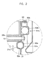
- the balancing devices comprise annular races 51a and 51b concentrically formed on inner and outer sides of the front and rear panels 31 and 32, and a plurality of balls 52a and 52b (which serve as counterweights) are seated in the races 51a and 51b.
- the inner race 51a and the outer race 51b protrude inwardly and outwardly respectively.
- the inner race 51a and the outer race 51b are welded to each other to form a seal.
- the races 51a and 51b contain a predetermined amount of oil to allow the balls 51a and 51b to move freely.
- the races 51a and 51b each comprise a combination of the front panel 31 and a plate member 53 coupled thereto.
- the outer race 51b protrudes outwardly to facilitate the provision of the lifter 33b. That is, the outer race 51b is formed from the combination of the outwardly protruding groove 53b, provided in the plate member 53, and the planar front panel 31.
- the area of the front panel 31 in contact with the end portion of the lifter 33b is planar to enable the lifter 33b to be manufactured easily by bending the side panel 33 radially inwardly.
- the inner race 51a which does not interfere with the lifter 33b is formed from a combination of the outwardly protruding groove 53a in the plate member 53 and an inwardly extending groove 31a in the front panel 31.
- Deformation of the spin basket 30 that may occur during manufacturing is prevented by minimising the depth of the inward groove 31a and the outward groove 53a.
- the plate member 53, the front panel 31 and the rear panel 32 constituting the races 51a and 51b are additionally joined to each other by a bolt 13 (refer to Figure 1).
- the following description relates to the operation of the drum washing machine with the balancing device.
- the electric motor 40 rotates the spin basket 30 in either a forward and reverse direction to generate suds and carry out the washing process aided by the action of the lifters 33b formed on the side panel 33 of the spin basket 30 which agitates the laundry.
- Water is removed from the laundry during the spin cycle using centrifugal force generated when the spin basket 30 rotates at high speeds, and drains into the tub 20 through the holes 33a formed on the side panel 33.
- the vibration created by the uneven distribution of laundry can be reduced by the following procedure.
- the laundry is located on the bottom of the spin basket 30 in the initial stage of the spin drying process.
- centrifugal force is created as a result of rotating the spin basket at high speed, the balls 52a and 52b move to the opposite side of the imbalance along the corresponding races 51a and 51b thus compensating for the out of balance condition of the spin basket 30 and preventing the vibration and eccentric rotation thereof.
- the spin basket 30 rotates essentially from its geometric centre due to the laundry being unevenly distributed in the spin basket 30.
- the centrifugal force from the geometric centre and that of the spin basket's actual centre of rotation simultaneously act on the balls 52a and 52b in the races 51a and 51b, so that they relocate to a predetermined position to oppose the imbalance.
- the balls 52a and 52b turn about the geometric centre of the spin basket 30, thus making the spin basket 30's centre of rotation correspond to the geometric centre.
- the unbalanced state of the spin basket 30 is thereby countered to eliminate the vibration and noise.
- the drum washing machine equipped with the balancing device of the present invention, prevents the spin basket from imbalanced rotation by dynamically counteracting any imbalances that may occur as a result of an uneven arrangement of laundry therein, and eliminates the vibration and noise created during rotation.
- the balancing device may also prevent unnecessary wear of the components used to support the rotation of the spin basket and abnormal noise created by friction.
- the areas of the front and rear panels that contact the lifters are planar, and, since both ends of the lifters are flat themselves, the manufacturing of the lifters is facilitated.
Landscapes
- Engineering & Computer Science (AREA)
- Textile Engineering (AREA)
- General Engineering & Computer Science (AREA)
- Mechanical Engineering (AREA)
- Physics & Mathematics (AREA)
- Acoustics & Sound (AREA)
- Aviation & Aerospace Engineering (AREA)
- Main Body Construction Of Washing Machines And Laundry Dryers (AREA)
- Accessory Of Washing/Drying Machine, Commercial Washing/Drying Machine, Other Washing/Drying Machine (AREA)
Claims (2)
- Trommelwaschmaschine (30), die folgendes umfaßt:dadurch gekennzeichnet, daß die kreisförmigen Laufringe (51b) durch Raupenblechglieder (53) ausgebildet sind, die an flachen Außenbereichen der entsprechenden Endverkleidungen (31, 32) angebracht sind, und daß die Aufnehmer (33b) radial einwärts gebogene Bereiche der Seitenverkleidung (33) umfassen und sich auf ganzer Länge zwischen den Endverkleidungen (31, 32) erstrecken.eine rotierbar angebrachte Trommel (30) zum Aufnehmen einer Wäscheladung, wobei die Trommel ein Paar Endverkleidungen (31, 32) aufweist, die durch eine röhrenförmige Seitenverkleidung (33) getrennt sind;Aufnehmer (33b), die von der Seitenverkleidung (33) aus radial nach innen vorstehen;kreisförmige Laufringe (51b), die koaxial zur Trommel (30) angeordnet und an den beiden Enden der Trommel positioniert sind; undeine Mehrzahl von Kugeln (52b) in den Laufringen,
- Waschmaschine nach Anspruch 1, die auf jeder Endverkleidung (31, 32) einen weiteren, bezüglich der Aufnehmer (33b) radial einwärts angeordneten Laufring (51a) aufweist.
Applications Claiming Priority (2)
| Application Number | Priority Date | Filing Date | Title |
|---|---|---|---|
| KR2019960013850U KR200145371Y1 (ko) | 1996-05-30 | 1996-05-30 | 드럼세탁기의 밸런싱장치 |
| KR9613850 | 1996-05-30 |
Publications (2)
| Publication Number | Publication Date |
|---|---|
| EP0810319A1 EP0810319A1 (de) | 1997-12-03 |
| EP0810319B1 true EP0810319B1 (de) | 2001-05-09 |
Family
ID=19457349
Family Applications (1)
| Application Number | Title | Priority Date | Filing Date |
|---|---|---|---|
| EP97303715A Expired - Lifetime EP0810319B1 (de) | 1996-05-30 | 1997-05-30 | Waschmaschine |
Country Status (7)
| Country | Link |
|---|---|
| US (1) | US5816074A (de) |
| EP (1) | EP0810319B1 (de) |
| JP (1) | JP2954087B2 (de) |
| KR (1) | KR200145371Y1 (de) |
| CN (1) | CN1095897C (de) |
| DE (1) | DE69704743T2 (de) |
| TR (1) | TR199700437A2 (de) |
Cited By (2)
| Publication number | Priority date | Publication date | Assignee | Title |
|---|---|---|---|---|
| US7082793B2 (en) | 2002-02-08 | 2006-08-01 | Bsh Bosch Und Siemens Hausgeraete Gmbh | Drum-type washing machine having a laundry drum which can be loaded from the front |
| CN102535100A (zh) * | 2011-09-02 | 2012-07-04 | 无锡小天鹅通用电器有限公司 | 滚筒洗衣机的滚筒 |
Families Citing this family (11)
| Publication number | Priority date | Publication date | Assignee | Title |
|---|---|---|---|---|
| US6648365B1 (en) | 1997-01-08 | 2003-11-18 | The Burton Corporation | Snowboard binding |
| US6219328B1 (en) * | 1997-10-31 | 2001-04-17 | Funai Electric Co., Ltd. | Disc rotating apparatus |
| US6578225B2 (en) * | 2000-05-25 | 2003-06-17 | Skf Autobalance Systems Ab | Low-speed prebalancing for washing machines |
| SE518472C2 (sv) * | 2001-02-06 | 2002-10-15 | Electrolux Ab | Anordning för balansering av roterande kroppar i t.ex. tvättmaskiner |
| US20040221624A1 (en) * | 2002-06-20 | 2004-11-11 | Silvano Fumagalli | Washington machine for household use with two compartments |
| KR100587307B1 (ko) * | 2004-06-09 | 2006-06-08 | 엘지전자 주식회사 | 드럼세탁기 및 드럼세탁기의 드럼 |
| ITMC20080007A1 (it) * | 2008-01-16 | 2009-07-17 | Meccanica Generale Srl | Metodo per la realizzazione di un supporto portacuscinetti in lamiera stampata. |
| KR101629672B1 (ko) * | 2009-06-29 | 2016-06-14 | 삼성전자 주식회사 | 세탁기 및 세탁기의 제조방법 |
| EP3862477B1 (de) * | 2020-02-10 | 2024-08-14 | The Procter & Gamble Company | Waschvorrichtungen mit dynamischen auswuchtanordnungen |
| EP3862478B1 (de) | 2020-02-10 | 2025-03-05 | The Procter & Gamble Company | Dynamische auswuchtanordnungen und waschvorrichtungen mit einem oder mehreren drehfedern |
| EP3862479A1 (de) | 2020-02-10 | 2021-08-11 | The Procter & Gamble Company | Aufhängungslose wäschevorrichtungen und verfahren zum auswuchten einer wäschevorrichtung |
Family Cites Families (12)
| Publication number | Priority date | Publication date | Assignee | Title |
|---|---|---|---|---|
| US2836046A (en) * | 1952-05-08 | 1958-05-27 | Maytag Co | Tumbler type washing machines |
| US2984094A (en) * | 1957-11-08 | 1961-05-16 | Frame Sa | Washing machine |
| FR1213067A (fr) * | 1957-11-08 | 1960-03-29 | Frame | Machine à laver |
| DE1912481U (de) * | 1961-07-24 | 1965-03-18 | Siemens Elektrogeraete Gmbh | Einrichtung zum schleudern von wasche mit elastischer aufhaengung des trommelaggregats. |
| NL7112526A (de) * | 1971-09-11 | 1973-03-13 | ||
| GB1598399A (en) * | 1977-06-02 | 1981-09-16 | Hitachi Ltd | Drum type automatic electric washing machine |
| CN86204056U (zh) * | 1986-09-05 | 1987-05-06 | 杨效禹 | 全自动滚筒洗衣机 |
| AU632439B2 (en) * | 1989-10-05 | 1992-12-24 | Sanyo Electric Co., Ltd. | Drum-type washing machine |
| US5460017A (en) * | 1992-05-21 | 1995-10-24 | Eti Technologies Inc. | Weight compensating apparatus |
| CA2069120C (en) * | 1992-05-21 | 2005-04-26 | Anton Gasafi | Weight compensating method and apparatus |
| JPH0725961A (ja) * | 1993-07-15 | 1995-01-27 | Matsushita Electric Ind Co Ltd | 洗濯機部品 |
| KR0175118B1 (ko) * | 1994-03-18 | 1999-05-01 | 가나이 쯔도무 | 세탁기 및 균형체 |
-
1996
- 1996-05-30 KR KR2019960013850U patent/KR200145371Y1/ko not_active Expired - Fee Related
-
1997
- 1997-05-22 US US08/861,569 patent/US5816074A/en not_active Expired - Lifetime
- 1997-05-28 JP JP9138971A patent/JP2954087B2/ja not_active Expired - Fee Related
- 1997-05-29 TR TR97/00437A patent/TR199700437A2/xx unknown
- 1997-05-30 CN CN97113698A patent/CN1095897C/zh not_active Expired - Fee Related
- 1997-05-30 EP EP97303715A patent/EP0810319B1/de not_active Expired - Lifetime
- 1997-05-30 DE DE69704743T patent/DE69704743T2/de not_active Expired - Lifetime
Cited By (4)
| Publication number | Priority date | Publication date | Assignee | Title |
|---|---|---|---|---|
| US7082793B2 (en) | 2002-02-08 | 2006-08-01 | Bsh Bosch Und Siemens Hausgeraete Gmbh | Drum-type washing machine having a laundry drum which can be loaded from the front |
| DE10205306B4 (de) * | 2002-02-08 | 2006-12-28 | BSH Bosch und Siemens Hausgeräte GmbH | Trommelwaschmaschine mit einer von vorn beschickbaren Wäschetrommel |
| CN102535100A (zh) * | 2011-09-02 | 2012-07-04 | 无锡小天鹅通用电器有限公司 | 滚筒洗衣机的滚筒 |
| CN102535100B (zh) * | 2011-09-02 | 2014-01-22 | 无锡小天鹅通用电器有限公司 | 滚筒洗衣机的滚筒 |
Also Published As
| Publication number | Publication date |
|---|---|
| EP0810319A1 (de) | 1997-12-03 |
| DE69704743D1 (de) | 2001-06-13 |
| KR970062459U (ko) | 1997-12-11 |
| US5816074A (en) | 1998-10-06 |
| TR199700437A2 (xx) | 1997-12-21 |
| JPH1052593A (ja) | 1998-02-24 |
| KR200145371Y1 (ko) | 1999-06-15 |
| CN1095897C (zh) | 2002-12-11 |
| JP2954087B2 (ja) | 1999-09-27 |
| CN1169485A (zh) | 1998-01-07 |
| DE69704743T2 (de) | 2002-02-28 |
Similar Documents
| Publication | Publication Date | Title |
|---|---|---|
| EP0781882B2 (de) | Trommelmaschine mit Auswuchtvorrichtungen | |
| US5850749A (en) | Balancing device for a drum washing machine | |
| EP0808932B1 (de) | Waschmaschine | |
| JP2755567B2 (ja) | ドラム型洗濯機の洗濯槽 | |
| JP2957144B2 (ja) | 洗濯機用ボールバランサ | |
| EP0810318B1 (de) | Waschmaschine | |
| EP0810319B1 (de) | Waschmaschine | |
| EP0806515B1 (de) | Waschmaschine | |
| CA2111541A1 (en) | Balancer for an automatic washer | |
| US5906756A (en) | Method of making balancing device for a drum washing machine | |
| JPH04240488A (ja) | ドラム式洗濯機 | |
| KR0134130Y1 (ko) | 드럼 세탁기의 밸런싱장치 | |
| KR0136040Y1 (ko) | 드럼세탁기의 밸런싱장치 | |
| KR0136039Y1 (ko) | 드럼세탁기의 밸런싱장치 | |
| KR0136042Y1 (ko) | 드럼세탁기의 밸런싱장치 | |
| KR0136041Y1 (ko) | 드럼세탁기의 밸런싱장치 | |
| KR200145370Y1 (ko) | 드럼세탁기의 밸런싱장치 | |
| KR20010009545A (ko) | 드럼세탁기의 회전조 | |
| KR200145372Y1 (ko) | 드럼세탁기의 밸런싱장치 |
Legal Events
| Date | Code | Title | Description |
|---|---|---|---|
| PUAI | Public reference made under article 153(3) epc to a published international application that has entered the european phase |
Free format text: ORIGINAL CODE: 0009012 |
|
| AK | Designated contracting states |
Kind code of ref document: A1 Designated state(s): DE FR GB IT NL |
|
| 17P | Request for examination filed |
Effective date: 19980331 |
|
| AKX | Designation fees paid |
Free format text: DE FR GB IT NL |
|
| RBV | Designated contracting states (corrected) |
Designated state(s): DE FR GB IT NL |
|
| 17Q | First examination report despatched |
Effective date: 19990617 |
|
| GRAG | Despatch of communication of intention to grant |
Free format text: ORIGINAL CODE: EPIDOS AGRA |
|
| GRAG | Despatch of communication of intention to grant |
Free format text: ORIGINAL CODE: EPIDOS AGRA |
|
| GRAH | Despatch of communication of intention to grant a patent |
Free format text: ORIGINAL CODE: EPIDOS IGRA |
|
| GRAH | Despatch of communication of intention to grant a patent |
Free format text: ORIGINAL CODE: EPIDOS IGRA |
|
| GRAA | (expected) grant |
Free format text: ORIGINAL CODE: 0009210 |
|
| AK | Designated contracting states |
Kind code of ref document: B1 Designated state(s): DE FR GB IT NL |
|
| ITF | It: translation for a ep patent filed | ||
| REF | Corresponds to: |
Ref document number: 69704743 Country of ref document: DE Date of ref document: 20010613 |
|
| ET | Fr: translation filed | ||
| REG | Reference to a national code |
Ref country code: GB Ref legal event code: IF02 |
|
| PLBE | No opposition filed within time limit |
Free format text: ORIGINAL CODE: 0009261 |
|
| STAA | Information on the status of an ep patent application or granted ep patent |
Free format text: STATUS: NO OPPOSITION FILED WITHIN TIME LIMIT |
|
| 26N | No opposition filed | ||
| PGFP | Annual fee paid to national office [announced via postgrant information from national office to epo] |
Ref country code: NL Payment date: 20080501 Year of fee payment: 12 |
|
| PGFP | Annual fee paid to national office [announced via postgrant information from national office to epo] |
Ref country code: IT Payment date: 20080530 Year of fee payment: 12 |
|
| NLV4 | Nl: lapsed or anulled due to non-payment of the annual fee |
Effective date: 20091201 |
|
| PG25 | Lapsed in a contracting state [announced via postgrant information from national office to epo] |
Ref country code: NL Free format text: LAPSE BECAUSE OF NON-PAYMENT OF DUE FEES Effective date: 20091201 |
|
| PG25 | Lapsed in a contracting state [announced via postgrant information from national office to epo] |
Ref country code: IT Free format text: LAPSE BECAUSE OF NON-PAYMENT OF DUE FEES Effective date: 20090530 |
|
| REG | Reference to a national code |
Ref country code: FR Ref legal event code: PLFP Year of fee payment: 19 |
|
| PGFP | Annual fee paid to national office [announced via postgrant information from national office to epo] |
Ref country code: GB Payment date: 20150422 Year of fee payment: 19 Ref country code: DE Payment date: 20150422 Year of fee payment: 19 |
|
| PGFP | Annual fee paid to national office [announced via postgrant information from national office to epo] |
Ref country code: FR Payment date: 20150422 Year of fee payment: 19 |
|
| REG | Reference to a national code |
Ref country code: DE Ref legal event code: R119 Ref document number: 69704743 Country of ref document: DE |
|
| GBPC | Gb: european patent ceased through non-payment of renewal fee |
Effective date: 20160530 |
|
| REG | Reference to a national code |
Ref country code: FR Ref legal event code: ST Effective date: 20170131 |
|
| PG25 | Lapsed in a contracting state [announced via postgrant information from national office to epo] |
Ref country code: DE Free format text: LAPSE BECAUSE OF NON-PAYMENT OF DUE FEES Effective date: 20161201 Ref country code: FR Free format text: LAPSE BECAUSE OF NON-PAYMENT OF DUE FEES Effective date: 20160531 |
|
| PG25 | Lapsed in a contracting state [announced via postgrant information from national office to epo] |
Ref country code: GB Free format text: LAPSE BECAUSE OF NON-PAYMENT OF DUE FEES Effective date: 20160530 |