EP0810372A2 - Pompe à palettes - Google Patents
Pompe à palettes Download PDFInfo
- Publication number
- EP0810372A2 EP0810372A2 EP97108653A EP97108653A EP0810372A2 EP 0810372 A2 EP0810372 A2 EP 0810372A2 EP 97108653 A EP97108653 A EP 97108653A EP 97108653 A EP97108653 A EP 97108653A EP 0810372 A2 EP0810372 A2 EP 0810372A2
- Authority
- EP
- European Patent Office
- Prior art keywords
- pressure
- vane pump
- locking
- rotor
- pump according
- Prior art date
- Legal status (The legal status is an assumption and is not a legal conclusion. Google has not performed a legal analysis and makes no representation as to the accuracy of the status listed.)
- Withdrawn
Links
Images
Classifications
-
- F—MECHANICAL ENGINEERING; LIGHTING; HEATING; WEAPONS; BLASTING
- F04—POSITIVE - DISPLACEMENT MACHINES FOR LIQUIDS; PUMPS FOR LIQUIDS OR ELASTIC FLUIDS
- F04C—ROTARY-PISTON, OR OSCILLATING-PISTON, POSITIVE-DISPLACEMENT MACHINES FOR LIQUIDS; ROTARY-PISTON, OR OSCILLATING-PISTON, POSITIVE-DISPLACEMENT PUMPS
- F04C14/00—Control of, monitoring of, or safety arrangements for, machines, pumps or pumping installations
- F04C14/24—Control of, monitoring of, or safety arrangements for, machines, pumps or pumping installations characterised by using valves controlling pressure or flow rate, e.g. discharge valves or unloading valves
-
- F—MECHANICAL ENGINEERING; LIGHTING; HEATING; WEAPONS; BLASTING
- F04—POSITIVE - DISPLACEMENT MACHINES FOR LIQUIDS; PUMPS FOR LIQUIDS OR ELASTIC FLUIDS
- F04C—ROTARY-PISTON, OR OSCILLATING-PISTON, POSITIVE-DISPLACEMENT MACHINES FOR LIQUIDS; ROTARY-PISTON, OR OSCILLATING-PISTON, POSITIVE-DISPLACEMENT PUMPS
- F04C2/00—Rotary-piston machines or pumps
- F04C2/30—Rotary-piston machines or pumps having the characteristics covered by two or more groups F04C2/02, F04C2/08, F04C2/22, F04C2/24 or having the characteristics covered by one of these groups together with some other type of movement between co-operating members
- F04C2/34—Rotary-piston machines or pumps having the characteristics covered by two or more groups F04C2/02, F04C2/08, F04C2/22, F04C2/24 or having the characteristics covered by one of these groups together with some other type of movement between co-operating members having the movement defined in groups F04C2/08 or F04C2/22 and relative reciprocation between the co-operating members
- F04C2/356—Rotary-piston machines or pumps having the characteristics covered by two or more groups F04C2/02, F04C2/08, F04C2/22, F04C2/24 or having the characteristics covered by one of these groups together with some other type of movement between co-operating members having the movement defined in groups F04C2/08 or F04C2/22 and relative reciprocation between the co-operating members with vanes reciprocating with respect to the outer member
- F04C2/3566—Rotary-piston machines or pumps having the characteristics covered by two or more groups F04C2/02, F04C2/08, F04C2/22, F04C2/24 or having the characteristics covered by one of these groups together with some other type of movement between co-operating members having the movement defined in groups F04C2/08 or F04C2/22 and relative reciprocation between the co-operating members with vanes reciprocating with respect to the outer member the inner and outer member being in contact along more than one line or surface
-
- F—MECHANICAL ENGINEERING; LIGHTING; HEATING; WEAPONS; BLASTING
- F04—POSITIVE - DISPLACEMENT MACHINES FOR LIQUIDS; PUMPS FOR LIQUIDS OR ELASTIC FLUIDS
- F04C—ROTARY-PISTON, OR OSCILLATING-PISTON, POSITIVE-DISPLACEMENT MACHINES FOR LIQUIDS; ROTARY-PISTON, OR OSCILLATING-PISTON, POSITIVE-DISPLACEMENT PUMPS
- F04C2270/00—Control; Monitoring or safety arrangements
- F04C2270/20—Flow
- F04C2270/205—Controlled or regulated
Definitions
- the invention relates to a vane pump with the features mentioned in the preamble of claim 1.
- Vane pumps of the generic type have a housing in which a rotor is set in rotation.
- the circumferential surface of the rotor has at least one control surface which, viewed in the circumferential direction, is delimited on both sides by separating regions.
- the control surface and the separating areas interact with at least one locking wing, which is accommodated in a groove in the wall of the fixed housing and is pressed against the control surface.
- the rotary movement of the rotor delimits spaces with variable volumes that are delimited by the blocking vanes. Due to the periodic change in the size of the volumes, a fluid is drawn in and released again under an overpressure.
- vane pumps for example, as power steering pumps in motor vehicles.
- the vane pumps are driven by a drive device of the motor vehicle, the delivery rate of the vane pumps depending on the speed is.
- the disadvantage here is that the rotor of the locking vane pump is rotatably coupled to the drive shaft of the drive device, so that different delivery rates occur at different speeds. For example, when driving on the expressway quickly, a large delivery volume is provided which is not required at this point in time, since steering assistance is not necessary when driving straight ahead at high speed.
- the invention has for its object to provide a vane pump of the generic type, which is simple and which allows a flow rate limitation.
- a vane pump with the features mentioned in claim 1.
- a throttle point is assigned to the suction inlet and a pressure-dependent closing or opening device is assigned to the pressure outlet, it is possible in a simple manner to limit the delivery quantity to realize.
- the pressure-dependent closing or opening device which is preferably designed as a check valve, allows the fluid-foam mixture formed at the throttle point to be influenced such that the gas components of the fluid-foam mixture are compressed before a connection to the pressure side the vane pump is released.
- the effort for the suction throttling is considerably reduced. Due to the unambiguous assignment of the suction chamber and the pressure chamber in the case of blocking vane pumps, that is to say they have a fixed angular position so that there are no moving displacement spaces, the suction throttling already known from vane pumps can surprisingly can be transferred to a vane pump with significantly reduced effort.
- the opening pressure of the closing or opening device is adjustable. This allows the opening pressure to be set very advantageously to the operating conditions of the vane pump.
- the redissolving process of the gas components in the fluid to be conveyed can be optimized so that the closing or opening device only opens at a compression phase in which the gas components of the fluid-foam mixture are completely redissolved.
- the opening pressure of the closing or opening device can be easily adapted to different fluids to be pumped, for example oil, and / or to changing operating conditions of the locking vane pump.
- the shape of the contour of the control surfaces is designed so that the redissolving of the fluid-foam mixture in front of the pressure-dependent closing or opening device is promoted.
- the contour is preferably designed so that a soft redissolution takes place, that is, the compression of the gas components of the fluid-foam mixture in front of the pressure-dependent closing or opening device is not sudden, but gradually according to the rotation of the rotor, so that sudden volume changes can be avoided by the condensation and redissolution of the gas.
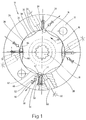
- FIG. 1 shows a section of a vane pump 10.
- the vane pump 10 has a housing 12 which has a circular pump chamber 14.
- a rotor 16, which can be driven by a drive shaft 18, is mounted within the pump chamber 14.
- the drive shaft 18 can be driven by an engine (not shown), for example a drive machine of a motor vehicle, so that the rotor 16 can be set in rotation within the pump chamber 14. In the example shown, the rotor 16 can be driven counterclockwise.
- the rotor 16 is disc-shaped and has on its circumferential surface 20 deviating from a circular contour several, in the example shown six, identically designed control surfaces 22 and separation regions 24.
- the control surfaces 22 and separation regions 24 are - seen in the circumferential direction - always provided alternately, so that each Control surface 22 is delimited by two separation areas 24.
- the maximum diameter of the rotor 16 is dimensioned such that its outer diameter in the region of the separating regions 24 practically corresponds to the inner diameter of the peripheral wall 26 corresponds to the pump chamber 14.
- the diameter of the rotor 16 in the area of the separating areas 24 is larger than its diameter in the area of the control surfaces 22, which are quasi formed by radially drawn-in areas.
- the width of the locking vanes 30 measured perpendicular to the plane of illustration of FIG. 1 corresponds approximately to the thickness of the rotor 16.
- the length of the locking vanes 30 measured in the radial direction is less than the depth of the grooves 28.
- the thickness of the locking vanes 30 is somewhat less than the width of the grooves 28, so that the locking wings 30 are mounted and guided in a radial direction against the force of an elastic element, for example a compression spring 32.
- a compression spring 32 is only indicated in the groove shown on the left in FIG.
- each of the locking vanes 30 is acted upon by a spring force in the radial direction via the compression spring 32.
- the locking wings 30 are acted upon by the compression spring 32 with a compressive force and pressed against the peripheral surface 20 of the rotor 16.
- the contact surface of the locking vanes 30 on the rotor 16 is chamfered here, so that there is a practically linear contact with the peripheral surface 20 of the rotor 16.
- the compressive force of the compression springs 32 is chosen so strong that the locking vanes 30 are pressed against the peripheral surface 20 of the rotor 16 at all drive speeds.
- a total of four grooves 28 with locking vanes 30 movably mounted therein are provided, each of which is arranged at an angle of 90 ° to one another in the peripheral wall 26 of the housing 12.
- the six separating areas 24 are arranged at an angle of 60 ° over the circumference of the rotor 16, so that the control surfaces 22 located between the separating areas 24 are also offset from one another by an angle of 60 °.
- the separation areas 24 and the control surfaces 22 all have exactly the same curve, that is to say the same contour.
- the control surfaces 22 have a first contour section 34 and a second contour section 36 which merge into one another via a section 38 which is curved in the form of a circular arc.
- the first contour section 34 lies in front of the contour section 36.
- the contour sections 34 and 36 each transition from or to a separating region 24 into the circular section 38.
- the contour sections 34 and 36 can run according to different, not shown exemplary embodiments, either mirror images of the circular section 38 or, depending on the mode of operation to be explained, have a different course.
- a pressure outlet 42 and a suction inlet 44 are assigned to each blocking wing 30.
- the pressure outlet 42 is in the direction of rotation indicated by the arrow 40 of the rotor 16 in front of the locking wing 30 and the suction inlet 44 is arranged after the blocking wing 30.
- the pressure outlet 42 is formed by a bore 46 which is cut by the peripheral wall 26 of the housing 12.
- the bore 46 is connected to a connection channel 48 which is only indicated here and which leads to a pressure connection of the vane pump 10.
- the connecting channels 48 of all pressure outlets 42 are brought together to the pressure connection of the vane pump 10.
- a channel 50 connected to the pressure outlet 42 opens into the groove 28 on the rear side of the blocking wings 30.
- the channel 50 is shown here only on a blocking wing 30, it being clear that this is provided in all the blocking wings 30.
- a check valve 52 is arranged within the connecting channels 48, the valve body 54 of which is pressed by the force of a spring element 56 against a valve seat 58 which seals the connecting channel 48.
- a spring force of the spring element 56 is adjustable according to an embodiment, not shown, so that an opening pressure of the check valve can be changed.
- the suction inlet 44 is formed by a connecting channel 60 which is guided through the housing 12 and opens into a suction connection of the vane pump 10.
- the connecting channels 60 each associated with a locking vane 30, are brought together to form a common suction connection of the locking vane pump 10.
- the suction connection of the vane pump 10 is assigned a throttle 61, also shown symbolically here, which the Flow rate of a fluid to be pumped, throttled to the vane pump 10. Since the structure and mode of operation of such chokes are generally known, this description will not be dealt with in more detail in the context of the present description.
- the blocking vane pump 10 is throttled so that it sucks in an essentially constant volume flow of the fluid to be conveyed, regardless of a speed of the rotor 16.
- the suction throttling is carried out regardless of the number of locking wings 30 and the choice of the contours of the control surfaces 22.
- the vane pump 10 shown in FIG. 1 has the following function, it being clear that the section of the housing 12 shown here is arranged pressure-tight within an entire housing of the vane pump 10.
- pressure plates can be provided on both sides of the rotor 16, which enable the pump chamber 14 to be closed in a pressure-tight manner and which have the corresponding passages for the pressure connections or suction connections.
- the rotor 16 is set in rotation via the drive shaft 18.
- the locking vanes 30 are pressed by the compression springs 32 against the peripheral surface 20 of the rotor 16. Due to the formation of the separation areas 24 and the control surfaces 22, the locking vanes 30 experience a radial movement during the rotation of the rotor 16.
- the locking vanes 30 are located in the area of the separating areas 24, the outer circumference of which practically corresponds to the inner circumference of the circumferential wall 26 in its radially outermost position.
- the locking vanes 30 When passing through a control surface 22, the locking vanes 30 are pressed radially inwards by the spring force of the compression spring 32 in accordance with the contour of the control surface 22.
- the contour of the control surfaces 22 results in chambers 62 in the region of each control surface, which have a certain volume. All chambers 62, that is to say all six chambers 62 in the example shown, have volumes of the same size.
- a control surface 22 is located in the area of a locking wing 30, the chamber 62 is divided into two areas 64 and 66 by the locking wing 30, which bears sealingly on the peripheral surface 20.
- the areas 64 and 66 change their volumes in accordance with the direction of rotation 40 of the rotor 16.
- the area 64 lying in front of the blocking wing in the direction of rotation changes its volume from a maximum which corresponds to the total volume of the chamber 62 to a minimum which ideally corresponds to the value zero.
- the decrease in volume over time is determined by the course of the contour sections 34, 36 and 38 of the control surfaces 22.
- the area 66 located after the blocking wing 30 changes its volume from a minimum, which ideally corresponds to the value zero, to a maximum, which corresponds to the volume of the chamber 62.
- a fluid to be conveyed is sucked from the suction inlet 44 within the area 66 by enlarging the area 66 up to the total volume of the chamber 62.
- the fluid is moved in the direction of the closest pressure outlet 42 within the chamber 62 and expelled there under pressure. This takes place due to the volume decreasing in the area 64, so that the fluid is pressed under pressure in the direction of arrow 68 from the pressure connection channels 48 to the pressure connection of the vane pump 10.
- the throttle point 61 forms a constriction for the fluid to be sucked in, for example an oil, so that there is an acceleration of the flowing oil there, the pressure simultaneously decreasing. This causes the pressure to drop below the vapor pressure of the oil, and vapor bubbles form, which produce an oil-foam mixture.
- This oil-foam mixture is sucked in by the increasing volume of the areas 66 and transported to the closest pressure outlet 42. As a result of the volume of the area 64 which decreases there, pressure builds up. Since the check valve 52 is closed, that is, the valve body 54 closes the valve seat 58 by the force of the spring 56 and the applied operating pressure, the pressure rises without pressure equalization being able to take place via the connecting channel 48.
- the dynamic processes taking place in the area 64 can be influenced by the shape of the contour of the control surfaces 22.
- the displacement volume per unit of time that is, the influence of the displaced volume within the reduction in the volume of the chambers 62 from their maxima to their minima, can be influenced.
- the compression of the oil-foam mixture before opening the check valve 52 can be set with the softest possible characteristic. This makes it possible for the gas components not to be redissolved suddenly, so that the pressure peaks associated with the redissolution can be minimized within the region 64. The mechanical load on the vane pump 10 is thus minimized overall.
Landscapes
- Engineering & Computer Science (AREA)
- Mechanical Engineering (AREA)
- General Engineering & Computer Science (AREA)
- Physics & Mathematics (AREA)
- Fluid Mechanics (AREA)
- Rotary Pumps (AREA)
- Details And Applications Of Rotary Liquid Pumps (AREA)
Applications Claiming Priority (2)
| Application Number | Priority Date | Filing Date | Title |
|---|---|---|---|
| DE19623243 | 1996-05-30 | ||
| DE1996123243 DE19623243A1 (de) | 1996-05-30 | 1996-05-30 | Sperrflügelpumpe |
Publications (2)
| Publication Number | Publication Date |
|---|---|
| EP0810372A2 true EP0810372A2 (fr) | 1997-12-03 |
| EP0810372A3 EP0810372A3 (fr) | 1999-07-07 |
Family
ID=7796618
Family Applications (1)
| Application Number | Title | Priority Date | Filing Date |
|---|---|---|---|
| EP97108653A Withdrawn EP0810372A3 (fr) | 1996-05-30 | 1997-05-29 | Pompe à palettes |
Country Status (3)
| Country | Link |
|---|---|
| EP (1) | EP0810372A3 (fr) |
| JP (1) | JPH1054375A (fr) |
| DE (1) | DE19623243A1 (fr) |
Cited By (1)
| Publication number | Priority date | Publication date | Assignee | Title |
|---|---|---|---|---|
| WO2010075834A3 (fr) * | 2008-12-17 | 2011-03-10 | Ixetic Hückeswagen Gmbh | Pompe à ailettes |
Family Cites Families (8)
| Publication number | Priority date | Publication date | Assignee | Title |
|---|---|---|---|---|
| US2492687A (en) * | 1946-04-30 | 1949-12-27 | Cincinnati Milling Machine Co | Hydraulic pump |
| US2786421A (en) * | 1953-11-24 | 1957-03-26 | Hamilton Gordon | Rotary pump or motor |
| DE1091049B (de) * | 1958-12-10 | 1960-10-13 | Veltrup Werke K G | Drehkolbenmotor |
| US3216362A (en) * | 1963-10-14 | 1965-11-09 | Gen Motors Corp | Flexible ring pump drive device |
| DE2513073A1 (de) * | 1975-03-25 | 1976-10-07 | Walter Murmann | Druckfluessigkeits-drehkolbenpumpe oder -motor |
| DE3005656A1 (de) * | 1980-02-15 | 1981-08-20 | Zahnradfabrik Friedrichshafen Ag, 7990 Friedrichshafen | Rotationskolbenpumpe |
| DE3506629A1 (de) * | 1984-03-01 | 1985-10-03 | Barmag Barmer Maschinenfabrik Ag, 5630 Remscheid | Hydrauliksysteme |
| DE4415663B4 (de) * | 1994-05-04 | 2006-04-20 | Zf Friedrichshafen Ag | Flügelzellenpumpe |
-
1996
- 1996-05-30 DE DE1996123243 patent/DE19623243A1/de not_active Withdrawn
-
1997
- 1997-05-29 EP EP97108653A patent/EP0810372A3/fr not_active Withdrawn
- 1997-05-30 JP JP14271897A patent/JPH1054375A/ja active Pending
Cited By (1)
| Publication number | Priority date | Publication date | Assignee | Title |
|---|---|---|---|---|
| WO2010075834A3 (fr) * | 2008-12-17 | 2011-03-10 | Ixetic Hückeswagen Gmbh | Pompe à ailettes |
Also Published As
| Publication number | Publication date |
|---|---|
| EP0810372A3 (fr) | 1999-07-07 |
| DE19623243A1 (de) | 1998-01-08 |
| JPH1054375A (ja) | 1998-02-24 |
Similar Documents
| Publication | Publication Date | Title |
|---|---|---|
| DE69716812T2 (de) | Spiralverdichter mit Einrichtung zur Kapazitätsänderung | |
| DE3319822C2 (de) | Hydraulikpumpe mit Vorkompressionsventil | |
| DE19917506A1 (de) | Verstellbare Verdrängerpumpe | |
| DE102016121241B4 (de) | Hydraulischer Antrieb, hydraulischer Motor und integrierte Pumpe mit dem hydraulischen Antrieb | |
| DE3800324A1 (de) | Fluegelzellenverdichter | |
| WO2009092719A2 (fr) | Pompe à engrenage intérieur, à volume variable | |
| DE19623242C1 (de) | Sperrflügelpumpe | |
| DE3428254A1 (de) | Rotationsverdichter | |
| EP0509077B1 (fr) | Pompe a pistons, notamment pompe a pistons radiaux | |
| EP1259737B1 (fr) | Dispositif de regulation pour pompes volumetriques | |
| DE102017204145A1 (de) | Ölmehrfachpumpe und Kraftfahrzeug mit einer solchen Ölmehrfachpumpe | |
| DE4108126C2 (de) | Flügelzellenpumpe | |
| DE3812487C2 (de) | Flügelzellenverdichter mit variabler Förderleistung | |
| EP0810372A2 (fr) | Pompe à palettes | |
| DE4008522C2 (fr) | ||
| WO2007039405A1 (fr) | Pompe a palettes | |
| DE3607351A1 (de) | Radialkolbenpumpe | |
| DE102005040702B4 (de) | Rotationspumpe | |
| EP1025363B1 (fr) | Pompe volumetrique | |
| DE29622888U1 (de) | Sperrflügelpumpe | |
| DE3801306A1 (de) | Fluegelzellenverdichter | |
| DE3414535C2 (fr) | ||
| DE19517627B4 (de) | Sperrflügelpumpe | |
| WO2005001291A1 (fr) | Pompe | |
| DE19721582A1 (de) | Sperrflügelpumpe |
Legal Events
| Date | Code | Title | Description |
|---|---|---|---|
| PUAI | Public reference made under article 153(3) epc to a published international application that has entered the european phase |
Free format text: ORIGINAL CODE: 0009012 |
|
| AK | Designated contracting states |
Kind code of ref document: A2 Designated state(s): DE FR GB IT |
|
| PUAL | Search report despatched |
Free format text: ORIGINAL CODE: 0009013 |
|
| AK | Designated contracting states |
Kind code of ref document: A3 Designated state(s): DE FR GB IT |
|
| RIC1 | Information provided on ipc code assigned before grant |
Free format text: 6F 04C 2/356 A, 6F 04C 15/04 B |
|
| STAA | Information on the status of an ep patent application or granted ep patent |
Free format text: STATUS: THE APPLICATION IS DEEMED TO BE WITHDRAWN |
|
| 18D | Application deemed to be withdrawn |
Effective date: 19991201 |