EP0810407A2 - Procédure et installation pour la récupération de la chaleur sensible et latente dans les fumées d'un foyer - Google Patents
Procédure et installation pour la récupération de la chaleur sensible et latente dans les fumées d'un foyer Download PDFInfo
- Publication number
- EP0810407A2 EP0810407A2 EP97108363A EP97108363A EP0810407A2 EP 0810407 A2 EP0810407 A2 EP 0810407A2 EP 97108363 A EP97108363 A EP 97108363A EP 97108363 A EP97108363 A EP 97108363A EP 0810407 A2 EP0810407 A2 EP 0810407A2
- Authority
- EP
- European Patent Office
- Prior art keywords
- heat
- heating water
- exchange medium
- heat exchanger
- condensate
- Prior art date
- Legal status (The legal status is an assumption and is not a legal conclusion. Google has not performed a legal analysis and makes no representation as to the accuracy of the status listed.)
- Granted
Links
Images


Classifications
-
- F—MECHANICAL ENGINEERING; LIGHTING; HEATING; WEAPONS; BLASTING
- F24—HEATING; RANGES; VENTILATING
- F24H—FLUID HEATERS, e.g. WATER OR AIR HEATERS, HAVING HEAT-GENERATING MEANS, e.g. HEAT PUMPS, IN GENERAL
- F24H1/00—Water heaters, e.g. boilers, continuous-flow heaters or water-storage heaters
- F24H1/10—Continuous-flow heaters, i.e. heaters in which heat is generated only while the water is flowing, e.g. with direct contact of the water with the heating medium
- F24H1/107—Continuous-flow heaters, i.e. heaters in which heat is generated only while the water is flowing, e.g. with direct contact of the water with the heating medium using fluid fuel
-
- F—MECHANICAL ENGINEERING; LIGHTING; HEATING; WEAPONS; BLASTING
- F24—HEATING; RANGES; VENTILATING
- F24D—DOMESTIC- OR SPACE-HEATING SYSTEMS, e.g. CENTRAL HEATING SYSTEMS; DOMESTIC HOT-WATER SUPPLY SYSTEMS; ELEMENTS OR COMPONENTS THEREFOR
- F24D12/00—Other central heating systems
- F24D12/02—Other central heating systems having more than one heat source
-
- F—MECHANICAL ENGINEERING; LIGHTING; HEATING; WEAPONS; BLASTING
- F24—HEATING; RANGES; VENTILATING
- F24D—DOMESTIC- OR SPACE-HEATING SYSTEMS, e.g. CENTRAL HEATING SYSTEMS; DOMESTIC HOT-WATER SUPPLY SYSTEMS; ELEMENTS OR COMPONENTS THEREFOR
- F24D3/00—Hot-water central heating systems
- F24D3/08—Hot-water central heating systems in combination with systems for domestic hot-water supply
-
- B—PERFORMING OPERATIONS; TRANSPORTING
- B05—SPRAYING OR ATOMISING IN GENERAL; APPLYING FLUENT MATERIALS TO SURFACES, IN GENERAL
- B05B—SPRAYING APPARATUS; ATOMISING APPARATUS; NOZZLES
- B05B1/00—Nozzles, spray heads or other outlets, with or without auxiliary devices such as valves, heating means
-
- Y—GENERAL TAGGING OF NEW TECHNOLOGICAL DEVELOPMENTS; GENERAL TAGGING OF CROSS-SECTIONAL TECHNOLOGIES SPANNING OVER SEVERAL SECTIONS OF THE IPC; TECHNICAL SUBJECTS COVERED BY FORMER USPC CROSS-REFERENCE ART COLLECTIONS [XRACs] AND DIGESTS
- Y02—TECHNOLOGIES OR APPLICATIONS FOR MITIGATION OR ADAPTATION AGAINST CLIMATE CHANGE
- Y02B—CLIMATE CHANGE MITIGATION TECHNOLOGIES RELATED TO BUILDINGS, e.g. HOUSING, HOUSE APPLIANCES OR RELATED END-USER APPLICATIONS
- Y02B30/00—Energy efficient heating, ventilation or air conditioning [HVAC]
Definitions
- the present invention relates to a method for using the residual heat and the latent heat comprising residual heat of an exhaust gas of a combustion system, in particular if a burner is only operated temporarily, in which the exhaust gas emits heat to a heat exchange medium in a residual heat exchanger and heat from the heat exchange medium Heating water in a heating water circuit, which comprises a heating water boiler, is transferred.
- the present invention relates to a device for using the residual heat and the latent heat comprising residual heat of an exhaust gas of a combustion system, in particular if a burner is only occasionally actuated, which comprises a residual heat exchanger, through which heat is released from the exhaust gas to a heat exchange medium.
- the present invention is therefore based on the object of improving a method and a device of the type mentioned at the outset in such a way that a larger proportion of the residual heat of the exhaust gas can be used than conventional methods and devices.
- the concept according to the invention has the advantage that the residual heat for heating the heat exchange medium can also be used during the time in which a burner of the furnace is at a standstill. For a majority of days in a heating period, the average daily boiler load is usually below 20%. Therefore, the concept according to the invention in particular improves the efficiency of the firing system in relation to an entire heating period.
- the concept according to the invention also offers the advantage that temperature fluctuations of the condensate are kept lower than that during an operating time of the burner Temperature fluctuations in the heating water in the boiler. This prevents the condensation temperature increases too much during burner operation. This in turn enables lower condensation temperatures and therefore higher efficiencies for the furnace.
- the volume of the amount of heat exchange medium through which heat is transferred to the heating water is advantageously greater than approximately three times the volume of the heating water boiler that absorbs the heating water.
- the method works particularly favorably if the volume of the quantity of heat exchange medium through which heat is transferred to the heating water is approximately five times greater than the volume of the heating water boiler which absorbs the heating water.
- the heat is transferred to heating water in a heating water return so that the heat exchange medium does not overheat.
- heat is transferred to the heating water directly from the heat exchange medium condensate heated in the residual heat exchanger. This can reduce heat losses.
- the heat transfer from the heat exchange medium to the heating water can take place in a particularly simple manner in that the heating water is passed through a condensate sump of the residual heat exchanger. As a result, no heat loss occurs due to the condensate medium being guided to give off heat to the heating water and, moreover, a liquid quantity of heat exchange medium is directly provided by the condensate sump.
- the heating water for heat absorption is passed through a heat exchange medium-heating water heat exchanger, which receives the heated heat exchange medium coming directly from the residual heat exchanger.
- the residual heat exchanger can be kept structurally simpler, since there is no need for heating water through the residual heat exchanger.
- the heat exchange medium can absorb heat from the exhaust gas, it is advantageous if it is conveyed in a condensate circuit.
- the heat exchange medium is conducted in a residual heat exchanger condensate circuit, which comprises the heat exchange medium-heating water heat exchanger, in which the heat exchange medium gives off heat to the heating water, then temperature fluctuations of the condensate can be reduced particularly well, especially if the heat exchange medium has a large heat capacity.
- the heat exchange medium in the residual heat exchanger condensate circuit is continuously conveyed by a pump in order to maintain a uniform circulation of the heat exchange medium.
- the heat exchange medium in the residual heat exchanger condensate circuit can also be conveyed by means of convection or gravity, so that a pump can be dispensed with.
- a further improvement in the efficiency of the firing system results if service water is led through the condensate sump of the residual heat exchanger to absorb heat from the heat exchange medium, since this ensures that the condensate is cooled further.
- process water preheated by the heat exchange medium is fed to a process water / heating water heat exchanger.
- preheated service water is already available to the service water / heating water heat exchanger, which promotes faster and more energy-saving heating to an intended end temperature of the service water.
- hot water preheated by the heat exchange medium can also be fed to a hot water storage tank which is flowed through by heating water for heating the hot water.
- the object on which the invention is based is achieved in that the device has a device for transferring heat from the heat exchange medium to heating water comprises whose heat exchange medium-absorbing volume is greater than a heating water-absorbing volume of a heating water boiler, and that the device is arranged in a heating water return of a heating water circuit.
- the device according to the invention thus offers the advantages already stated in connection with the method according to the invention according to claim 1.
- Preferred embodiments of the device according to the invention are the subject of claims 19 to 42, the advantages of which have also already been explained in connection with the preferred embodiments of the method according to the invention according to claims 2 to 17.
- thermosensor is arranged in the residual heat exchanger, by means of which the temperature of the condensate can be monitored. Excessively high condensate temperatures, which prevent the residual heat from the exhaust gas from being used, can then be immediately recognized and suitable measures taken, for example by feeding the burner exhaust gases directly into a chimney or by switching off the pump through which the heat exchange medium is transported in the condensate circuit.
- a heating water supply has a mixer, through which heating water can be conducted from the heating water return to a heating supply.
- the heating system has an additional control option with which its efficiency can be improved.
- a first embodiment of a device according to the invention for utilizing the residual heat of an exhaust gas from a firing system shown schematically as a whole in FIG. 1 and designated as a whole, comprises a burner 32 as a firing system, which has a heating water boiler 34 for heating the volume 35 contained in a heating water receiving volume Heating water is connected.
- the burner 32 can be operated with any liquid, gaseous and solid fuels, for example with heating oil, natural gas or lignite.
- An exhaust pipe 36 for the hot exhaust gas arising in the combustion process in the burner 32 leads from the burner 32 through a combustion chamber 37 of the boiler 34 to a temperature changer 38 which is designed as a four-armed pipe cross, one of the arms up and down and two more arms point in horizontal directions.
- the exhaust pipe 36 is connected to one of the horizontally oriented arms of the temperature changer 38.
- An exhaust gas supply pipe 40 is connected to the downward-pointing arm of the temperature changer 38 and opens at its other end at an exhaust gas inlet 42 into a lower region of a residual heat exchanger 44.
- the exhaust pipe 36 opens directly into the residual heat exchanger via the exhaust gas inlet 42 without the interposition of a temperature changer 38.
- the residual heat exchanger 44 is described in detail below. It has, for example, the shape of an upright hollow cylinder which is closed at the top and bottom and, in addition to the exhaust gas inlet 42, is provided in its lower region with a condensate outlet 46 and a condensate overflow 48 arranged above it.
- the residual heat exchanger 44 has an inlet 50 and an outlet 51 in its lower region, by means of which lines can be routed through the lower region of the residual heat exchanger. Several such entries and exits can also be provided.
- the residual heat exchanger 44 has an exhaust gas outlet 52 in its upper region and an upper condensate inlet 54 arranged above it.
- the exhaust gas outlet 52 is connected via an exhaust gas discharge pipe 56 to the horizontally oriented arm of the temperature changer 38 opposite the exhaust gas line 36.
- a chimney feed pipe 58 is connected to the upward-pointing arm of the temperature changer 38 and leads to a chimney (not shown).
- the chimney feed pipe 58 is connected directly to the exhaust gas outlet 52 without the interposition of a temperature changer. In this case, exhaust gas cannot get into the chimney directly from the exhaust pipe 36.
- the temperature changer 38 has a deflection plate 60 which can be pivoted between a pass-through and a diversion position.
- the exhaust pipe 36 and the exhaust gas supply pipe 40 are connected to one another, but are sealed off from the exhaust gas discharge pipe 56 and the chimney supply pipe 58.
- the exhaust gas discharge pipe 56 and the chimney supply pipe 58 are also connected to one another.
- the exhaust pipe 36 and the chimney feed pipe 58 are connected to one another and sealed off from the exhaust gas supply pipe 40 and the exhaust gas discharge pipe 56, so that in this position the baffle plate 60 is hot 32 coming exhaust gas escapes directly from the exhaust pipe 36 into the chimney feed pipe 58 without first reaching the residual heat exchanger 44.
- the residual heat exchanger 44 is part of a condensate circuit, designated as a whole by 62.
- the direction of flow of the condensate through the condensate circuit 62 is indicated in FIG. 1 by means of arrowheads.
- the condensate outlet 46 of the residual heat exchanger 44 is connected via a condensate line 64 to a neutralizer 66 which serves to neutralize acidic condensate components and for this purpose is filled, for example, with hydrolite which has an MgO content of approximately 75% and water, carbon dioxide as further constituents as well as traces of calcium, iron, aluminum and silicon oxide.
- the neutralizer 66 is preferably connected to the condensate circuit 62 such that the condensate flows through it from top to bottom.
- Another condensate line 68 leads from the neutralizer 66 to a condensate filter 70 which has a mesh size of, for example, less than 100 ⁇ m.
- the condensate filter 70 can also be integrated in the neutralizer 66, the condensate line 68 then being omitted.
- a further condensate line 72 leads from the condensate filter 70 to an air injector 74.
- the air injector 74 is used for the oxidation of sulfite ions dissolved in the condensate to non-toxic sulfate ions by means of air, which is fed to the air injector 74 via an air supply line 76 connected to it.
- the air injector 74 is arranged inside the condensate circuit 62 in the flow direction behind the neutralizer 66 in order to avoid air siphon formation in the neutralizer 66 due to oxidation air injected in the air injector 74.
- the residual heat exchanger 44 has a further condensate outlet 47 in its lower region and that condensate can flow from this condensate outlet 47 via a line 73 into the line 72. In this case, no air injector is provided.
- the air injector 74 is connected via a condensate line 78 to a suction-side inlet of a condensate pump 80, which is used to convey the condensate through the condensate circuit 62.
- the pump is controlled by a control unit (not shown in the figure) which can register the actuation or non-actuation of the burner 32.
- a condensate line 82 leads from a pressure-side outlet of the condensate pump 80 to the upper condensate inlet 54 of the residual heat exchanger 44.
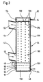
- the residual heat exchanger 44 of the first embodiment of the device according to the invention is a monodisperse condensate spray heat exchanger, which is shown schematically in FIG. 2.
- the monodisperse condensate spray heat exchanger 44 comprises a horizontally arranged cylindrical nozzle plate 132 which defines the cylindrical interior of the condensate spray heat exchanger 44 divides into a nozzle prechamber 134 arranged above the nozzle plate 132 and a heat exchanger space 136 arranged below the nozzle plate 132.
- the nozzle plate 132 is penetrated by a plurality of nozzle bores 138 in the vertical direction.
- the center axes of adjacent nozzle bores 138 are at a distance from one another which preferably corresponds to 15 to 20 times the diameter of the outlet opening of a nozzle bore 138.
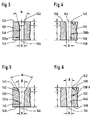
- a first embodiment 138a of such a nozzle bore 138 shown in FIG. 3 has an inlet 142 opening on an upper side 140 of the nozzle plate 132 in the form of an upwardly widening truncated cone with a vertical axis 144, opening angle ⁇ and length H.
- the inlet 142 opens on its underside into a cylindrical nozzle duct 146 of length L, which is coaxial with the inlet 142, the diameter D of which corresponds to the smallest diameter of the frusto-conical inlet 142 and which opens on an underside 148 of the nozzle plate 132.
- the opening angle ⁇ is preferably less than approximately 60 °
- the length H of the inlet 142 is greater than or approximately equal to the diameter D of the nozzle channel 146 and the length L des Nozzle channel 146 is selected to be larger than approximately three times and smaller than approximately five times the diameter D of the nozzle channel 146.
- An alternative second embodiment of a nozzle bore 138 in the nozzle plate 132 shown in FIG. 4 and designated as a whole by 138b differs from the first embodiment shown in FIG. 3 only in that the inlet 142 does not have the outer surface of a truncated cone, but rather a section of the circumferential surface of a circle with radius R is limited. Otherwise, the second embodiment of FIG. 4 corresponds to the embodiment shown in FIG. 3.
- the radius R is preferably chosen to be larger or approximately equal to the diameter of the nozzle channel 146.
- An alternative third embodiment of a nozzle bore 138 in the nozzle plate 132 shown in FIG. 5 and designated as a whole by 138c differs from the first embodiment shown in FIG. 3 only in that the nozzle channel 146 is not cylindrical, but the shape of one has an upwardly widening truncated cone with the opening angle ⁇ and the length L.
- the smallest diameter of the frusto-conical inlet 142 coincides with the largest diameter of the frusto-conical nozzle channel 146 and is larger than the mouth diameter D of the nozzle bore 138c.
- the third embodiment 138c is the same as the first embodiment 138a shown in FIG. 3.
- the opening angle ⁇ is preferably less than approximately 60 °, the opening angle ⁇ is less than approximately 10 °, the length H of the inlet 142 is greater than approximately 1/5 of the orifice diameter D and the length L of the nozzle channel 146 is chosen to be greater than approximately three times the orifice diameter D.
- An alternative fourth embodiment of a nozzle bore 138 in the nozzle plate 132 shown in FIG. 6 and designated as a whole by 138d differs from the third embodiment 138c shown in FIG. 5 only in that the boundary surface of the inlet 142 does not the circumferential surface of a truncated cone, but a section of the circumferential surface of a circular radius of radius R.
- the fourth embodiment 138d is the same as the third embodiment 138c.
- the opening angle ⁇ is preferably less than approximately 10 °, the radius R is greater than approximately 1/5 of the orifice diameter D and the length L of the nozzle channel 146 is greater than selected about three times the mouth diameter D.
- the condensate line 128 opens above the nozzle plate 132 through the side wall of the residual heat exchanger 44 at the upper condensate inlet 54 into the nozzle prechamber 134.
- the condensate overflow 48 opens through the side wall of the residual heat exchanger 44 into the heat exchanger space 136.
- the space from the bottom of the heat exchanger space 136 to the level of the mouth opening of the condensate overflow 48 is filled with condensate, which forms a condensate sump 150.
- the volume 155 which is taken up by the condensate sump 150 is preferably approximately five times larger than the heating water-absorbing volume 35 of the heating water boiler 34.
- the side wall of the residual heat exchanger 44 has inlets 50 and outlets 51, through which lines can be routed through the condensate sump 150 between an inlet 50 and an outlet 51.
- the device according to the invention comprises a heating water circuit 84, which includes the heating water boiler 34 heated by the burner 32.
- a heating water line 86 leads from an output of the heating water boiler 34 to a branch 88. From the branch another line 90 leads to an input of a mixer 92. A first output of the mixer 92 is connected via a further line 94 to an input side of a pump 96. A further line 98 connects the pump 96 to a radiator arrangement 100, which is used, for example, to give off heat to the air from inside.
- a boiler flow 83 includes lines 86 and 90 and a heater flow 85 includes lines 94 and 98.
- a line 102 leads from the radiator arrangement 100 to an inlet 50 of the residual heat exchanger 44.
- the heating water is led through the condensate sump 150 of the residual heat exchanger 44 by means of a heat exchanger coil 104.
- Another line 106 leads from the heat exchanger coil 104 through an outlet 51 to the heating water boiler 34.
- the lines 102 and 106 form a heating water return 105 with the heat exchanger coil 104.
- a line 110 leads from a branch 108, which lies in line 106, to a second input of mixer 92.
- a further heating water line 112 leads from the branch 88 in the heating water feed line 83 to a pump 114 and from an output of the pump 114 a further line 116 leads to a heating water inlet of a heating water / process water heater 118.
- a line 120 leads from a heating water outlet of this water heater to a junction 122 in the heating water return line 105, the junction 122 being arranged between the junction 108 and a heating water return inlet into the boiler 34.
- the device comprises, as shown in FIG. 1, the hot water supply designated as a whole by 152.
- Cold process water is supplied to the residual heat exchanger 44 for preheating via a process water line 154.
- the process water line 154 is led through the condensate sump 150 of the residual heat exchanger 44, the Service water line 154 in the residual heat exchanger 44 has a heat exchanger unit 156.
- This can be, for example, a heat exchanger coil or a plate heat exchanger unit.
- Another process water line 158 which is coupled to an outlet 51 of the residual heat exchanger 44, leads to a process water inlet of the heating water process water heater 118. From an outlet of this process heater, another process water line 160 leads to process water extraction points (not shown), such as a hot water tap. The process water is heated in the water heater 118 by the heating water in the countercurrent principle.
- the domestic water line 154 and the domestic water line 158 are connected directly via a line 162, i.e. without carrying out domestic water through the residual heat exchanger 44, so that the domestic water supply 152 is decoupled from the condensate circuit 62.
- the first embodiment of the device 30 according to the invention described above works as follows:
- Heating water from the heating water boiler 34 passes through the boiler flow 83 and the heating flow 85 into the radiator arrangement 100, releases heat when it passes through it, and returns through the heating water return 105 to the heating water boiler 34.
- the average temperature of the heating water boiler 34 decreases until it drops below one Switch-on temperature of the burner 32 drops, at which the burner 32 is started to heat the heating water in the heating water boiler 34 again.
- the burner 32 is switched off again.
- a drop in the temperature in the heating water boiler 34 can also be brought about by taking hot water from the hot water supply line 160, which takes place at short intervals, which follow one another at irregular intervals, since the hot water flows through the Heating water hot water heater 118 removes heat from the heating water in the heating water boiler 34.
- combustion of the fuel (oil, coal, gas) in the burner 32 produces an exhaust gas which flows through the exhaust pipe 36 to the temperature changer 38.
- the deflection plate 60 of the temperature changer 38 is in the pass-through position, so that it directs the exhaust gas coming from the exhaust gas line 36 through the exhaust gas supply pipe 40 to the exhaust gas inlet 42 of the residual heat exchanger 44.
- the direction of flow of the exhaust gas is indicated by arrows in FIGS. 1 and 2.
- the condensate pump 80 in the condensate circuit 62 is also put into operation.
- the condensate flows through the condensate line 82 and the upper condensate inlet 54 into the nozzle prechamber 134 of the residual heat exchanger 44.
- the condensate is pressed under a slight overpressure of, for example, 0.1 bar through the nozzle bores 138 in the nozzle plate 132 into the heat exchanger space 136.
- a condensate jet 178 which falls freely through the heat exchanger space 136, emerges from each of the nozzle bores 138 and, after falling through a decay length, breaks down into the drops of a condensate spray 180.
- the decay of a condensate jet 178 with a round cross section takes place according to one of the following decay mechanisms: Rayleigh decay, membrane decay or fiber decay.
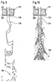
- FIG. 7 shows a Rayleigh decay of a condensate jet 178 with a short decay length.
- Rayleigh decay a monodisperse drop chain is formed from the condensate jet 178, the diameter of each drop being approximately twice the original jet diameter.
- the Rayleigh decay therefore leads to the formation of a monodisperse condensate spray 180.
- the flow rate of the condensate through the nozzle channels 146 is set by means of the condensate pump 80, that the Reynolds number of condensate flow at the orifices of the nozzle channels 146 is less than about 5,000, preferably less than about 2,500, and greater than about 100, preferably greater than about 500.
- the flow rate of the condensate at the mouth openings of the nozzle bores 138 corresponds to the ratio of the condensate volume flow in the condensate circuit 62 and the total area of the mouth openings of all nozzle bores 138 of the nozzle plate 132.
- the relative speed between the falling drops and the gas atmosphere surrounding them is adjusted in such a way that the Weber number of drops is less than 10, preferably less than 5, in particular less than 2.
- the relative speed u r corresponds to the sum of the falling speed of the condensate drops and the flow rate of the exhaust gas in the residual heat exchanger 44, the latter being inversely proportional to the cross-sectional area of the heat exchanger space 136 and thus essentially by the dimensioning of the residual heat exchanger 44.
- FIG. 8 also shows a Rayleigh decay of a condensate jet 178 into a monodisperse condensate spray 180, but with a longer decay length than in FIG. 7.
- the condensate surface in the heat exchanger space 136 is reduced, so that a higher heat exchanger space 136 is required to exchange a predetermined amount of heat between the exhaust gas and the condensate; however, the risk of condensate droplets being carried away by the exhaust gas flow and being carried out of the residual heat exchanger 44 decreases, in particular in the upper region of the heat exchanger space 136, where the exhaust gas outlet 52 is arranged.
- FIG. 9 An undesired membrane decay of a condensate jet 178 is shown in FIG. 9.
- the condensate jet 178 decays into a condensate spray 180 with a very wide droplet size spectrum.
- a wide range of droplet sizes is disadvantageous, since on the one hand it comprises small droplets which are carried away by the exhaust gas stream and are carried out of the residual heat exchanger if no additional downstream droplet separator is provided.
- the condensate spray 180 with a wide droplet size spectrum also comprises relatively large droplets or filaments which have only a small specific surface and thus a small specific heat exchange area.
- Membrane decay of the condensate jet 178 can occur if the Reynolds or Weber number lies outside the above-mentioned range, or if the nozzle bores 138 are unfavorable, if the bore walls are too rough or if the condensate adheres too weakly to the walls of the nozzle bores 138 .
- FIG. 10 shows an also undesirable fiber decay of a condensate jet 178.
- the condensate jet 178 decays into a condensate spray 180 with a wide droplet size spectrum, which has the disadvantages already mentioned in connection with the membrane decay and also requires a higher pump output.
- Fiber decay like membrane decay, can occur if the above-mentioned favorable range of Reynolds or Weber numbers is left or the nozzle bores 138 are unfavorably shaped, the walls of the nozzle bores 138 are too rough or the condensate is too weak at the Walls of the nozzle bores 138 adheres.
- the monodisperse condensate spra formed in the heat exchanger space 136 of the residual heat exchanger 44 offers not only a large heat exchanger area for the heat transfer from the hot exhaust gas from the exhaust gas supply pipe 40 to the condensate, but also a high heat transfer coefficient due to the use of the latent heat of the water vapor contained in the exhaust gas.
- the exhaust gas comes into contact with the drops of the monodisperse condensate spray 180, at least partially evaporates it and is thereby rapidly cooled.
- the sensible exhaust gas heat is converted into latent heat.
- the water vapor formed by partial evaporation of the condensate spray 180 flows together with the cooled exhaust gas and the water vapor already contained therein upwards against the falling direction of the condensate spray 180 in the heat exchanger space 138, the exhaust gas cooling further, so that in the upper area adjacent to the nozzle plate 132 In the heat exchanger space 136, the water vapor carried in the exhaust gas condenses on the drops of the condensate spray 180, the circulating condensate mass flow absorbing the latent heat contained in the steam.
- the amount of water vapor condensing in the upper region of the heat exchanger space 136 is greater than the amount of the condensate evaporated in the lower region of the heat exchanger space 136, so that as a result the water vapor that has reached the residual heat exchanger 44 with the exhaust gas condenses at least partially and thereby latent heat to the condensate mass flow releases in the condensate circuit 62.
- the condensate accordingly absorbs sensible and latent heat from the exhaust gas stream, it acts as a heat exchange medium for the exhaust gas of the burner 32.
- the amount of condensate arriving in the condensate sump 150 at the bottom of the heat exchanger space 136 is slightly larger than the amount of condensate entering the heat exchanger space 136 through the nozzle plate 132.
- the additional amount of condensate condensed per unit of time in the heat exchanger space 136 from the exhaust gas corresponds to approximately one thousandth to one hundredth of the amount of condensate entering the heat exchanger space 136 per unit of time through the nozzle plate 132, the mass of which in turn is preferably approximately 10 to 100 times the mass of the Exhaust gas entering the heat exchanger space 136 per unit time.
- the average drop size of the monodisperse condensate spray 180 is selected as a function of the flow rate of the exhaust gas in the heat exchanger space 136 such that the drops are not entrained by the exhaust gas flow from the heat exchanger space 136 through the exhaust gas outlet 52.
- the exhaust gas is not only cooled and dried in the residual heat exchanger 44, but also cleaned, since pollutants carried in the exhaust gas are dissolved in the condensate flow.
- pollutants carried in the exhaust gas are dissolved in the condensate flow.
- SO 2 formed is washed out of the exhaust gas.
- the exhaust gas cooled in the residual heat exchanger 44 passes through the exhaust gas discharge pipe 56 to the temperature changer 38, where it is deflected into the chimney supply pipe 58 by the deflection plate 60 in the pass-through position, so that it can finally escape into the atmosphere through the (not shown) chimney.
- the temperature changer 38 there is a moderate heat transfer from the hot exhaust gas stream entering through the exhaust gas line 36 to the cooled exhaust gas stream entering through the exhaust gas discharge pipe 56, due to which the cooled exhaust gas is heated above its dew point, i.e. when it exits the temperature changer 38 into the chimney feed pipe 58 is dry ("overheated") so that no condensation takes place in the chimney, which could lead to corrosion of the chimney.
- the drops of the condensate spray 180 get into the condensate sump 150 after the heat exchanger space 136 has fallen through.
- the condensate circulating in the condensate circuit 62 first reaches the neutralizer 66, in which a pH value of the condensate between about 6 and about 7 is set by adding neutralizing agents (for example hydrolite).
- neutralizing agents for example hydrolite
- the neutralized condensate is filtered in the condensate filter 70 and enters the air injector 74, where an air flow is fed through the air supply line 76, through which sulfite ions, which may be dissolved in the condensate, are oxidized to non-toxic sulfate ions.
- the condensate passes from the air injector 74 into the condensate pump 80, which maintains the condensate circulation in the condensate circuit 62, and further through the line 82 to the upper condensate inlet 54.
- 150 condensate collects in the condensate sump.
- the heating water in the heating water return 105 is passed through the condensate sump 150.
- the heat exchange medium heated in the condensate circuit 62 can thereby give off heat to the heating water in the heating water return 105.
- the condensate can also give off heat to the heating water when the burner 32 is not actuated.
- the condensate is cooled by the transfer of heat from the condensate to the heating water. This enables a lower temperature for the condensate and thus better utilization of the residual heat.
- the temperature in the condensate is monitored by a temperature sensor (not shown in the figure). If the heating arrangement 100 requires only a small amount of heating power, the heating water conducted in the heating water return 105 through the condensate sump 150 of the residual heat exchanger 44 can absorb little or no heat. Under certain circumstances it may even be the case that the condensate is warmed up by the heating water. In this case, a control unit (not shown in the figure) causes the baffle plate 60 to be brought into its blocking position, so that the exhaust gas passes directly into the chimney feed pipe 58, bypassing the residual heat exchanger 44.
- the preparation of hot water can also be included in the device 30.
- cold process water which originates, for example, from a public supply network, is routed via the process water supply 154 and the heat exchanger coil 156 through the condensate sump 150 of the residual heat exchanger 44.
- the process water is heated up and this preheated process water is heated to its desired temperature when it passes through the heating water process water heater 118.
- no process water is supplied to the residual heat exchanger 44 for preheating.
- the burner 32 can be controlled so that, if there is no heating operation, it is switched on as soon as hot domestic water is removed or only when hot water has been removed for a certain minimum time.
- the residual heat exchanger 44 has an outlet 190 which lies on a side wall of the residual heat exchanger 44 in the region of the condensate sump 150.
- Condensate is fed through a line 192 to a heat exchange medium / heating water heat exchanger 194. This takes up condensate in a volume that is preferably five times larger than the heating water-absorbing volume 35 of the heating water boiler 34.
- the condensate is fed through line 64 to the neutralizer 66.
- the condensate circuit 62 is otherwise arranged as already described above.
- This device has the advantage that the inlets 50 and the outlets 51 and the outlet 46 on the residual heat exchanger 44 can be dispensed with.
- the process for heating the heating water or the process water is the same as described above.
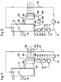
- a continuous-flow heater and a heat exchange medium / heating water heat exchanger are present.
- the condensate is passed through the heat exchange medium / heating water heat exchanger 194 in a residual heat exchanger condensate circuit 206.
- the residual heat exchanger 44 has an inlet 204 on a side wall in the region of the condensate sump 150, through which condensate conveyed through the heat exchange medium / heating water heat exchanger 194 can re-enter the condensate sump 150.
- a line 198 connects the condensate outlet 196 of the heat exchange medium heating water heat exchanger 194 to an inlet of a pump 200.
- a line 202 connects an outlet side of the pump to the inlet 204.
- the condensate is conveyed out of the heat exchange medium-heating water heat exchanger 194 by the continuously operating pump 200. Furthermore, the heat exchange medium is conveyed in the condensate circuit 62.
- the line 202 can also (not shown in FIG. 12) lead directly into the condensate circuit 62. This allows larger differences in the gravitational potential to be generated.
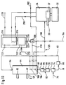
- the process water supply 154 is connected to an input of a three-way mixer 208.
- This three-way mixer 208 can in particular also be designed as a three-way valve, for example as a three-way check valve.
- a line 210 leads from a first outlet of the three-way mixer 208 to the residual heat exchanger 44, the process water being conducted through the condensate sump 150 of the residual heat exchanger by means of the heat exchanger unit 156, for example a heat exchanger coil.
- a line 212 runs from the heat exchanger unit 156 to an inlet 214 of a hot water storage tank 216.
- the hot water storage tank 216 is connected via a line 219 to a second outlet of the three-way mixer 208.
- heated heating water is conducted in the heating water boiler 34 through a line 218 through the hot used water storage 216.
- the heating water return 105 leads from the radiator arrangement 100 (not shown in FIG. 13) to the residual heat exchanger 44 or to the heat exchange medium-heating water heat exchanger 194. This arrangement is as described above.
- Pre-heated service water is fed via line 212 to the hot water storage tank 216 in the condensate sump 150 of the residual heat exchanger 44 or in the heat exchange medium / heating water heat exchanger 194.
- the three-way mixer 208 has a position such that the flow of cold hot water from the line 154 into the lines 210 and 219 is blocked. In contrast, the passage from line 219 to line 210 is open. As a result, process water can flow via line 219 from the hot water storage tank 216 to the residual heat exchanger 44 or the heat exchange medium / heating water heat exchanger 194 via the line 210 for heating by the heat exchange medium, and from there the preheated service water flows into the hot water storage tank 216.
- An outlet 221 for the line 219 from the hot water storage tank 216 is preferably arranged such that cool service water can flow into the line 210 by gravity and that preheated service water can flow through the line 212 to the hot water storage tank 216 by convection.
- the hot water storage tank 216 can be designed in a two-part form, which comprises a first storage tank 222, on which the inlet 214 and the outlet 221 are arranged, and a second storage tank 224, in which the used water is heated by means of the heating water carried in the line 218 .
- Pre-heated heating water is fed to the second storage 224 through a line 226 from the first storage 222 in the residual heat exchanger 44 or in the heat exchange medium-heating water heat exchanger 194.
- the first store 222 accordingly acts as a buffer between the line 154 for cold service water and the second store 224.
- a hot water storage tank 216 may be configured such that the first storage 222 and the second storage 224 are connected to one another and the connection is formed from a perforated disc (not shown in the figure), so that service water from the first storage 222 is direct can flow into the second memory 224. This has the advantage that there is no heat loss due to the transport of preheated service water from the first store 222 to the second store 224.
- a first storage 222 and a second storage 224 can also be designed in such a way that the heating water is conducted via line 218 through a heat exchanger unit, for example a plate heat exchanger unit, the heat exchanger unit being in a central region of the Hot water storage 216 is arranged.
- the heat exchanger unit is arranged and has a shape such that the second store 224 is formed by the area above the heat exchanger unit and the first store 222 is formed by the area below the heat exchanger unit.
- the volume of the second memory 224 is approximately twice to approximately ten times as large as the volume of the first memory 222.
- the burner 32 is switched on when hot domestic water is withdrawn through line 220, when the temperature in the hot domestic water storage 216 and in particular in the second storage 224 falls below a certain temperature or when hot domestic water is withdrawn for longer than a certain minimum time. It can also be provided that the burner 32 is actuated when one or more specific water tapping points are actuated, such as a tap for a bathtub. It is also possible that the burner 32 for hot water preparation is only activated when the user actuates a special switch.
Landscapes
- Engineering & Computer Science (AREA)
- Physics & Mathematics (AREA)
- Thermal Sciences (AREA)
- Chemical & Material Sciences (AREA)
- Combustion & Propulsion (AREA)
- Mechanical Engineering (AREA)
- General Engineering & Computer Science (AREA)
- Water Supply & Treatment (AREA)
- Instantaneous Water Boilers, Portable Hot-Water Supply Apparatuses, And Control Of Portable Hot-Water Supply Apparatuses (AREA)
- Air Supply (AREA)
- Heat-Pump Type And Storage Water Heaters (AREA)
Applications Claiming Priority (2)
| Application Number | Priority Date | Filing Date | Title |
|---|---|---|---|
| DE19621990A DE19621990A1 (de) | 1996-05-31 | 1996-05-31 | Verfahren und Vorrichtung zur Nutzung der die restliche fühlbare und die latente Wärme umfassenden Restwärme eines Abgases einer Feuerungsanlage |
| DE19621990 | 1996-05-31 |
Publications (3)
| Publication Number | Publication Date |
|---|---|
| EP0810407A2 true EP0810407A2 (fr) | 1997-12-03 |
| EP0810407A3 EP0810407A3 (fr) | 1998-11-25 |
| EP0810407B1 EP0810407B1 (fr) | 2002-10-09 |
Family
ID=7795863
Family Applications (1)
| Application Number | Title | Priority Date | Filing Date |
|---|---|---|---|
| EP97108363A Expired - Lifetime EP0810407B1 (fr) | 1996-05-31 | 1997-05-23 | Procédure et installation pour la récupération de la chaleur sensible et latente dans les fumées d'un foyer |
Country Status (3)
| Country | Link |
|---|---|
| EP (1) | EP0810407B1 (fr) |
| AT (1) | ATE225923T1 (fr) |
| DE (2) | DE19621990A1 (fr) |
Cited By (7)
| Publication number | Priority date | Publication date | Assignee | Title |
|---|---|---|---|---|
| EP1064499B1 (fr) * | 1998-06-08 | 2005-04-20 | Eero Erma | Deshumidificateur de gaz de fumees |
| GB2427017A (en) * | 2005-06-11 | 2006-12-13 | Ideal Boilers Ltd | Household water heating apparatus |
| NL1036296C2 (nl) * | 2008-12-09 | 2010-06-10 | Agpo Bv | Warmwaterketel. |
| CN102168888A (zh) * | 2011-02-25 | 2011-08-31 | 清华大学 | 一种接触式低温烟气余热深度回收利用系统 |
| CN102407070A (zh) * | 2011-11-21 | 2012-04-11 | 北京建筑工程学院 | 一种烟气余热回收利用与除尘净化复合型设备 |
| CN106440833A (zh) * | 2016-09-26 | 2017-02-22 | 刘启端 | 一种烟气的湿法除尘脱硫脱硝系统及方法 |
| CN108507005A (zh) * | 2017-02-27 | 2018-09-07 | 路西仁 | 一种柜式取暖炉 |
Families Citing this family (4)
| Publication number | Priority date | Publication date | Assignee | Title |
|---|---|---|---|---|
| DE19709804A1 (de) | 1997-03-10 | 1998-09-17 | Deutsch Zentr Luft & Raumfahrt | Verfahren und Vorrichtung zur Nutzung der Restwärme eines Abgases einer Feuerungsanlage |
| EP1809967B1 (fr) * | 2004-11-12 | 2013-01-09 | Zenex Technologies Ltd. | Utilisation d'un echangeur thermique avec une chaudiere a condensation |
| CN106642694A (zh) * | 2015-07-14 | 2017-05-10 | 北京华通兴远供热节能技术有限公司 | 烟气预加热生活热水装置 |
| CN110686311B (zh) * | 2019-10-25 | 2024-07-19 | 中山市创尔特智能家居科技有限公司 | 燃气壁炉 |
Family Cites Families (4)
| Publication number | Priority date | Publication date | Assignee | Title |
|---|---|---|---|---|
| DE2512233C3 (de) * | 1975-03-20 | 1981-06-04 | Fröling GmbH & Co Kessel-Apparatebau, 5063 Overath | Vorrichtung zur Ausnutzung der Rauchgase eines brennstoffbeheizten Heizungskessels |
| DE3145302A1 (de) * | 1981-11-14 | 1983-05-19 | Fröling GmbH & Co Kessel-Apparatebau, 5063 Overath | Verfahren und vorrichtung zur absenkung des schadstoffgehaltes hinter waermeerzeugern |
| DE3344089A1 (de) * | 1983-12-06 | 1985-06-20 | Karl Eberl | Vorrichtung fuer heizungsanlagen |
| DE19543449A1 (de) * | 1995-11-22 | 1997-05-28 | Deutsche Forsch Luft Raumfahrt | Verfahren und Vorrichtung zur Nutzung der restlichen fühlbaren und der latenten Wärme eines Abgases einer Feuerungsanlage |
-
1996
- 1996-05-31 DE DE19621990A patent/DE19621990A1/de not_active Withdrawn
-
1997
- 1997-05-23 EP EP97108363A patent/EP0810407B1/fr not_active Expired - Lifetime
- 1997-05-23 DE DE59708402T patent/DE59708402D1/de not_active Expired - Fee Related
- 1997-05-23 AT AT97108363T patent/ATE225923T1/de not_active IP Right Cessation
Non-Patent Citations (1)
| Title |
|---|
| None |
Cited By (10)
| Publication number | Priority date | Publication date | Assignee | Title |
|---|---|---|---|---|
| EP1064499B1 (fr) * | 1998-06-08 | 2005-04-20 | Eero Erma | Deshumidificateur de gaz de fumees |
| GB2427017A (en) * | 2005-06-11 | 2006-12-13 | Ideal Boilers Ltd | Household water heating apparatus |
| GB2427017B (en) * | 2005-06-11 | 2010-10-13 | Ideal Boilers Ltd | Household water heating apparatus |
| NL1036296C2 (nl) * | 2008-12-09 | 2010-06-10 | Agpo Bv | Warmwaterketel. |
| CN102168888A (zh) * | 2011-02-25 | 2011-08-31 | 清华大学 | 一种接触式低温烟气余热深度回收利用系统 |
| CN102168888B (zh) * | 2011-02-25 | 2013-02-27 | 清华大学 | 一种接触式低温烟气余热深度回收利用系统 |
| CN102407070A (zh) * | 2011-11-21 | 2012-04-11 | 北京建筑工程学院 | 一种烟气余热回收利用与除尘净化复合型设备 |
| CN102407070B (zh) * | 2011-11-21 | 2013-12-11 | 北京建筑工程学院 | 一种烟气余热回收利用与除尘净化复合型设备 |
| CN106440833A (zh) * | 2016-09-26 | 2017-02-22 | 刘启端 | 一种烟气的湿法除尘脱硫脱硝系统及方法 |
| CN108507005A (zh) * | 2017-02-27 | 2018-09-07 | 路西仁 | 一种柜式取暖炉 |
Also Published As
| Publication number | Publication date |
|---|---|
| ATE225923T1 (de) | 2002-10-15 |
| DE59708402D1 (de) | 2002-11-14 |
| EP0810407A3 (fr) | 1998-11-25 |
| EP0810407B1 (fr) | 2002-10-09 |
| DE19621990A1 (de) | 1997-12-04 |
Similar Documents
| Publication | Publication Date | Title |
|---|---|---|
| DE3614385C2 (fr) | ||
| EP1108187B1 (fr) | Procede de reduction des rejets de matieres polluantes de petites installations de chauffage et dispositif utilise a cet effet | |
| EP0172375A1 (fr) | Dispositif pour le chauffage d'un fluide et pour l'épuration de gaz brûlé des installations de chauffage | |
| EP0810407B1 (fr) | Procédure et installation pour la récupération de la chaleur sensible et latente dans les fumées d'un foyer | |
| EP0461515B1 (fr) | Dispositif de chauffage et de dégazage de l'eau | |
| WO1984003843A1 (fr) | Installation pour le traitement des gaz de combustion | |
| DE19614712A1 (de) | Vorrichtung zur Reinigung schadstoffbelasteter Abluft | |
| EP0775873A1 (fr) | Méthode et appareil pour récupérer la chaleur résiduaire sensible et latente dans les fumées d'un foyer | |
| EP0775872B1 (fr) | Méthode et appareil pour récupérer la chaleur résiduaire sensible et latente dans les fumées d'un foyer | |
| EP0814306B1 (fr) | Méthode et appareil pour récupérer la chaleur résiduaire sensible et latente dans les fumées d'un foyer | |
| DE8203728U1 (de) | Resorptionsvorgang zum entfernen farbloesungsmitteldaempfen | |
| EP0864816B1 (fr) | Procédure et installation pour la récupération de la chaleur résiduelle dans les fumées d'un foyer | |
| DE3715132C2 (fr) | ||
| DE19804989B4 (de) | Verfahren und Vorrichtung zum Vorwärmen einer einem Brenner einer Feuerungsanlage zugeführten Verbrennungsluft | |
| DE2109324C3 (de) | Abgasreinigungsvorrichtung | |
| DE60317538T2 (de) | Verfahren und vorrichtung zur behandlung von abgas aus verbrennungsanlagen | |
| DE4321250A1 (de) | Rohrbündel-Wärmetauscher | |
| EP0214934B1 (fr) | Dispositif d'évaporation et installation avec un tel dispositif pour la désalinition de l'eau de mer | |
| DE19804993C2 (de) | Verfahren und Vorrichtung zum Zuführen von Verbrennungsluft zu einem Brenner einer Feuerungsanlage | |
| WO1999040369A1 (fr) | Procede et dispositif pour prechauffer l'air de combustion achemine a un bruleur d'un equipement de chauffe | |
| DE3642041C2 (fr) | ||
| AT411393B (de) | Trinkwasserspeicher | |
| DE69810439T2 (de) | Wiederverwertungsanlage zur Gewinnung von Oel aus Kunststoffabfällen | |
| DE4302150A1 (de) | Einrichtung zur Abgasbehandlung der Abgase von Heizeinrichtungen | |
| DE1526942C (de) | Einrichtung zum Entgasen von Kesse !speisewasser |
Legal Events
| Date | Code | Title | Description |
|---|---|---|---|
| PUAI | Public reference made under article 153(3) epc to a published international application that has entered the european phase |
Free format text: ORIGINAL CODE: 0009012 |
|
| AK | Designated contracting states |
Kind code of ref document: A2 Designated state(s): AT CH DE FR LI |
|
| RAP1 | Party data changed (applicant data changed or rights of an application transferred) |
Owner name: DEUTSCHES ZENTRUM FUER LUFT- UND RAUMFAHRT E.V. |
|
| RAP3 | Party data changed (applicant data changed or rights of an application transferred) |
Owner name: DEUTSCHES ZENTRUM FUER LUFT- UND RAUMFAHRT E.V. |
|
| PUAL | Search report despatched |
Free format text: ORIGINAL CODE: 0009013 |
|
| AK | Designated contracting states |
Kind code of ref document: A3 Designated state(s): AT CH DE FR LI |
|
| 17P | Request for examination filed |
Effective date: 19990424 |
|
| 17Q | First examination report despatched |
Effective date: 20010618 |
|
| GRAG | Despatch of communication of intention to grant |
Free format text: ORIGINAL CODE: EPIDOS AGRA |
|
| GRAG | Despatch of communication of intention to grant |
Free format text: ORIGINAL CODE: EPIDOS AGRA |
|
| GRAH | Despatch of communication of intention to grant a patent |
Free format text: ORIGINAL CODE: EPIDOS IGRA |
|
| RAP1 | Party data changed (applicant data changed or rights of an application transferred) |
Owner name: DEUTSCHES ZENTRUM FUER LUFT- UND RAUMFAHRT E.V. |
|
| GRAH | Despatch of communication of intention to grant a patent |
Free format text: ORIGINAL CODE: EPIDOS IGRA |
|
| GRAA | (expected) grant |
Free format text: ORIGINAL CODE: 0009210 |
|
| AK | Designated contracting states |
Kind code of ref document: B1 Designated state(s): AT CH DE FR LI |
|
| REF | Corresponds to: |
Ref document number: 225923 Country of ref document: AT Date of ref document: 20021015 Kind code of ref document: T |
|
| REG | Reference to a national code |
Ref country code: CH Ref legal event code: NV Representative=s name: ISLER & PEDRAZZINI AG Ref country code: CH Ref legal event code: EP |
|
| REF | Corresponds to: |
Ref document number: 59708402 Country of ref document: DE Date of ref document: 20021114 |
|
| ET | Fr: translation filed | ||
| PLBE | No opposition filed within time limit |
Free format text: ORIGINAL CODE: 0009261 |
|
| STAA | Information on the status of an ep patent application or granted ep patent |
Free format text: STATUS: NO OPPOSITION FILED WITHIN TIME LIMIT |
|
| 26N | No opposition filed |
Effective date: 20030710 |
|
| PGFP | Annual fee paid to national office [announced via postgrant information from national office to epo] |
Ref country code: AT Payment date: 20050421 Year of fee payment: 9 |
|
| PGFP | Annual fee paid to national office [announced via postgrant information from national office to epo] |
Ref country code: DE Payment date: 20050504 Year of fee payment: 9 |
|
| PGFP | Annual fee paid to national office [announced via postgrant information from national office to epo] |
Ref country code: FR Payment date: 20050519 Year of fee payment: 9 |
|
| PGFP | Annual fee paid to national office [announced via postgrant information from national office to epo] |
Ref country code: CH Payment date: 20050524 Year of fee payment: 9 |
|
| PG25 | Lapsed in a contracting state [announced via postgrant information from national office to epo] |
Ref country code: AT Free format text: LAPSE BECAUSE OF NON-PAYMENT OF DUE FEES Effective date: 20060523 |
|
| PG25 | Lapsed in a contracting state [announced via postgrant information from national office to epo] |
Ref country code: LI Free format text: LAPSE BECAUSE OF NON-PAYMENT OF DUE FEES Effective date: 20060531 Ref country code: CH Free format text: LAPSE BECAUSE OF NON-PAYMENT OF DUE FEES Effective date: 20060531 |
|
| PG25 | Lapsed in a contracting state [announced via postgrant information from national office to epo] |
Ref country code: DE Free format text: LAPSE BECAUSE OF NON-PAYMENT OF DUE FEES Effective date: 20061201 |
|
| REG | Reference to a national code |
Ref country code: CH Ref legal event code: PL |
|
| REG | Reference to a national code |
Ref country code: FR Ref legal event code: ST Effective date: 20070131 |
|
| PG25 | Lapsed in a contracting state [announced via postgrant information from national office to epo] |
Ref country code: FR Free format text: LAPSE BECAUSE OF NON-PAYMENT OF DUE FEES Effective date: 20060531 |