EP0810492A2 - Entwicklerträgerelement, Entwicklungsgerät, Entwicklungsverfahren, Bilderzeugungsgerät und Arbeitseinheit - Google Patents
Entwicklerträgerelement, Entwicklungsgerät, Entwicklungsverfahren, Bilderzeugungsgerät und Arbeitseinheit Download PDFInfo
- Publication number
- EP0810492A2 EP0810492A2 EP97303595A EP97303595A EP0810492A2 EP 0810492 A2 EP0810492 A2 EP 0810492A2 EP 97303595 A EP97303595 A EP 97303595A EP 97303595 A EP97303595 A EP 97303595A EP 0810492 A2 EP0810492 A2 EP 0810492A2
- Authority
- EP
- European Patent Office
- Prior art keywords
- carrying member
- developer carrying
- developer
- particles
- developing
- Prior art date
- Legal status (The legal status is an assumption and is not a legal conclusion. Google has not performed a legal analysis and makes no representation as to the accuracy of the status listed.)
- Granted
Links
Images


Classifications
-
- G—PHYSICS
- G03—PHOTOGRAPHY; CINEMATOGRAPHY; ANALOGOUS TECHNIQUES USING WAVES OTHER THAN OPTICAL WAVES; ELECTROGRAPHY; HOLOGRAPHY
- G03G—ELECTROGRAPHY; ELECTROPHOTOGRAPHY; MAGNETOGRAPHY
- G03G15/00—Apparatus for electrographic processes using a charge pattern
- G03G15/06—Apparatus for electrographic processes using a charge pattern for developing
- G03G15/08—Apparatus for electrographic processes using a charge pattern for developing using a solid developer, e.g. powder developer
- G03G15/09—Apparatus for electrographic processes using a charge pattern for developing using a solid developer, e.g. powder developer using magnetic brush
- G03G15/0921—Details concerning the magnetic brush roller structure, e.g. magnet configuration
- G03G15/0928—Details concerning the magnetic brush roller structure, e.g. magnet configuration relating to the shell, e.g. structure, composition
-
- G—PHYSICS
- G03—PHOTOGRAPHY; CINEMATOGRAPHY; ANALOGOUS TECHNIQUES USING WAVES OTHER THAN OPTICAL WAVES; ELECTROGRAPHY; HOLOGRAPHY
- G03G—ELECTROGRAPHY; ELECTROPHOTOGRAPHY; MAGNETOGRAPHY
- G03G15/00—Apparatus for electrographic processes using a charge pattern
- G03G15/06—Apparatus for electrographic processes using a charge pattern for developing
- G03G15/08—Apparatus for electrographic processes using a charge pattern for developing using a solid developer, e.g. powder developer
- G03G15/0806—Apparatus for electrographic processes using a charge pattern for developing using a solid developer, e.g. powder developer on a donor element, e.g. belt, roller
- G03G15/0818—Apparatus for electrographic processes using a charge pattern for developing using a solid developer, e.g. powder developer on a donor element, e.g. belt, roller characterised by the structure of the donor member, e.g. surface properties
-
- Y—GENERAL TAGGING OF NEW TECHNOLOGICAL DEVELOPMENTS; GENERAL TAGGING OF CROSS-SECTIONAL TECHNOLOGIES SPANNING OVER SEVERAL SECTIONS OF THE IPC; TECHNICAL SUBJECTS COVERED BY FORMER USPC CROSS-REFERENCE ART COLLECTIONS [XRACs] AND DIGESTS
- Y10—TECHNICAL SUBJECTS COVERED BY FORMER USPC
- Y10T—TECHNICAL SUBJECTS COVERED BY FORMER US CLASSIFICATION
- Y10T428/00—Stock material or miscellaneous articles
- Y10T428/25—Web or sheet containing structurally defined element or component and including a second component containing structurally defined particles
- Y10T428/252—Glass or ceramic [i.e., fired or glazed clay, cement, etc.] [porcelain, quartz, etc.]
-
- Y—GENERAL TAGGING OF NEW TECHNOLOGICAL DEVELOPMENTS; GENERAL TAGGING OF CROSS-SECTIONAL TECHNOLOGIES SPANNING OVER SEVERAL SECTIONS OF THE IPC; TECHNICAL SUBJECTS COVERED BY FORMER USPC CROSS-REFERENCE ART COLLECTIONS [XRACs] AND DIGESTS
- Y10—TECHNICAL SUBJECTS COVERED BY FORMER USPC
- Y10T—TECHNICAL SUBJECTS COVERED BY FORMER US CLASSIFICATION
- Y10T428/00—Stock material or miscellaneous articles
- Y10T428/25—Web or sheet containing structurally defined element or component and including a second component containing structurally defined particles
- Y10T428/254—Polymeric or resinous material
-
- Y—GENERAL TAGGING OF NEW TECHNOLOGICAL DEVELOPMENTS; GENERAL TAGGING OF CROSS-SECTIONAL TECHNOLOGIES SPANNING OVER SEVERAL SECTIONS OF THE IPC; TECHNICAL SUBJECTS COVERED BY FORMER USPC CROSS-REFERENCE ART COLLECTIONS [XRACs] AND DIGESTS
- Y10—TECHNICAL SUBJECTS COVERED BY FORMER USPC
- Y10T—TECHNICAL SUBJECTS COVERED BY FORMER US CLASSIFICATION
- Y10T428/00—Stock material or miscellaneous articles
- Y10T428/29—Coated or structually defined flake, particle, cell, strand, strand portion, rod, filament, macroscopic fiber or mass thereof
- Y10T428/2982—Particulate matter [e.g., sphere, flake, etc.]
- Y10T428/2991—Coated
Definitions
- This invention relates to a developer carrying member used when an electrostatic latent image formed on an electrostatic latent image bearing member such as an electrophotographic photosensitive member or an electrostatic recording dielectric member is developed. It also relates to a developing apparatus, a developing method, an image forming apparatus and a process cartridge using such a developer carrying member.
- a developing assembly as shown in Fig. 7 As a developing apparatus used when electrostatic latent images formed on a photosensitive drum serving as an electrostatic latent image bearing member are developed by the use of a magnetic toner as a one-component type developer, a developing assembly as shown in Fig. 7 is known in the art. As shown in Fig. 7, a developer container 53 as shown in Fig. 6 holds a magnetic toner 54 as one-component type developer, and electric charge having a polarity reverse to the electric charge of the electrostatic image formed on a photosensitive drum 51 and to the development standard potential is imparted to magnetic toner particles by the friction between particles of the magnetic toner and the friction between a developing sleeve 58 as a developer carrying member and the magnetic toner particles.
- the magnetic toner thus charged is applied on the developing sleeve 58 by means of a magnetic blade 52 and then transported to the developing zone D at which the photosensitive drum 51 and the developing sleeve 58 face each other, where the magnetic toner carried on the developing sleeve 58 by the action of the magnetic field formed by a magnet 55 stationarily set therein is attracted to develop the electrostatic latent image on the photosensitive drum 51.
- Letter symbols A and B denote the rotating directions of the developing sleeve 58 and the photosensitive drum 51, respectively.
- Reference numeral 59 denotes a development bias means for applying a development bias voltage at the time of development; and 60, an agitating blade for agitating the magnetic toner 54 inside the developer container 53.
- the charge quantity of the toner applied on the developing sleeve becomes too large by contact with the developing sleeve, so that the toner and the developing sleeve attract each other on account of the reflective force of the developing sleeve surface and the toner turns immobile on the surface of the developing sleeve, thus, it does not move from the developing sleeve to the electrostatic latent image bearing member (drum).
- charge-up tends to occur. Once such charge-up has occurred, the toner forming an upper layer on the sleeve is hard to electrify and the quantity of toner participating in development is reduced, bringing about problems of, for example, line images being thinner and image density of solid images being thinner.
- the toner layer may be formed in a different state at image areas (areas where toner is consumed) and non-image areas to have been charged in different conditions.
- image areas areas where toner is consumed
- non-image areas to have been charged in different conditions.
- toners have been made smaller in particle diameter and made finer.
- toners in order to improve image quality such as resolution and sharpness to faithfully reproduce electrostatic latent images, it is common to use toners with a weight average particle diameter of about 6 to 9 ⁇ m.
- toners for the purpose of making copying time shorter and power consumption smaller, there is a tendency toward lower fixing temperature. Under such circumstances, the toner more tends to electrostatically adhere onto the developing sleeve and at the same time undergo external physical force, so that contamination of the developing sleeve surface and toner fusing are liable to occur.
- a developing sleeve comprising a metal substrate provided thereon with a coat layer formed of a resin in which a solid lubricant and a conductive fine powder such as carbon powder are dispersed.
- the above phenomenons seem to greatly decrease.
- the surface of the developing sleeve is not sufficiently even in its shape and also the surface of the developing sleeve has a smaller area to which triboelectric charges are imparted, so that uniform charging of toner and a rise in toner charging (or the quick electrification of toner) can not be sufficient in some cases. Accordingly, black spots around character line images may occur and image density may lower in an environment of high temperature and high humidity.
- this method is still not well satisfactory, which also leaves a problem concerning running performance because the coat layer may become brittle.
- Japanese Patent Application Laid-open No. 3-200986 discloses a method in which a developing sleeve comprising a metal substrate provided thereon with a conductive coat layer formed of a resin in which a solid lubricant, a conductive fine powder such as carbon powder and also spherical particles are dispersed is used in the developing apparatus.
- a developing sleeve comprising a metal substrate provided thereon with a conductive coat layer formed of a resin in which a solid lubricant, a conductive fine powder such as carbon powder and also spherical particles are dispersed is used in the developing apparatus.
- the developing sleeve surface can have an even shape, charging can be uniform and wear resistance can be improved.
- Japanese Patent Application Laid-open No. 2-176762 discloses a method in which a developing sleeve containing a charge control agent in a coat layer formed on the surface of the developing sleeve is used in the developing apparatus.
- a rise in toner charging and the uniform charging of toner can be improved to a certain extent, but the surface of the developing sleeve can not still have a charge-providing ability good enough to be well effective for a high image quality superior in character line sharpness and for the stability of image density in an environment of high temperature and high humidity.
- this method can not still be satisfactory in respect of running performance, and is sought to be further improved.
- an object of the present invention is to provide a developer carrying member in which a conductive coat layer formed on its surface may be hardly deteriorated by repeated copying or running, and which has a high durability and can give stable images; and a developing apparatus, a developing method, an image forming apparatus and a process cartridge having such a developer carrying member.
- Another object of the present invention is to provide a developer carrying member which does not cause problems such as density decrease, sleeve ghost and fog over a long period of time even under different environmental conditions and can stably give high-grade images having a good character line sharpness and a high image density; and a developing apparatus, a developing method, an image forming apparatus and a process cartridge which have such a developer carrying member.
- Still another object of the present invention is to provide a developer carrying member which can prevent toners from being non-uniformly charged on the developer carrying member surface when toners having small particle diameters are used, and can quickly and properly impart charges to toners; and a developing apparatus, a developing method, an image forming apparatus and a process cartridge which have such a developer carrying member.
- the present invention provides a developer carrying member comprising a substrate and a coat layer which covers the surface of the substrate, wherein; the coat layer contains at least a binder resin, conductive spherical particles having a number average particle diameter of from 0.3 ⁇ m to 30 ⁇ m and a true density of 3 g/cm 3 or below, and a nitrogen-containing heterocyclic compound; the particles and the compound being dispersed in the binder resin.
- the present invention also provides a developing apparatus comprising;
- the present invention still also provides a developing method comprising the steps of;
- the present invention further provides an image forming apparatus comprising;
- the present invention still further provides a process cartridge detachably mountable on a main assembly of an image forming apparatus, comprising;
- Fig. 1 schematically illustrates a developing apparatus according to an embodiment of the present invention, having a developer carrying member on which the coat layer of the present invention is formed.
- FIG. 2 schematically illustrates a developing apparatus according to another embodiment of the present invention, having a different developer layer thickness control member in the developing apparatus shown in Fig. 1.
- FIG. 3 schematically illustrates a developing apparatus according to a still another embodiment of the present invention, having a different developer layer thickness control member in the developing apparatus shown in Fig. 1.
- Fig. 4 schematically illustrates an image forming apparatus of the present invention.
- Fig. 5 schematically illustrates an example of the process cartridge of the present invention.
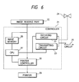
- Fig. 6 is a block diagram in a case where the image forming apparatus is used as a printer of a facsimile system.
- Fig. 7 diagrammatically illustrates a conventional developing apparatus having a developer carrying member on which no resin coat layer is formed.
- the present inventors have discovered that the charging performance for rapidly and uniformly charging the developer and the permanence of this charging performance can be more greatly improved than those of conventional cases, when the coat layer on the surface of the developer carrying member is constituted of a resin in which a nitrogen-containing heterocyclic compound is incorporated in addition to specific conductive spherical particles which impart irregularities (or concavities and convexities).
- the conductive spherical particles used in the coat layer which covers the surface of a substrate constituting the developer carrying member of the present invention will be described.
- the conductive spherical particles used in the present invention may have a number average particle diameter of from 0.3 ⁇ m to 30 ⁇ m, and preferably from 2 ⁇ m to 20 ⁇ m, and satisfy a true density of 3 g/cm 3 or below.
- Such conductive spherical particles are added so that the surface of the coat layer in the developer carrying member can retain a uniform surface roughness and also, even when the surface of the coat layer has worn, the surface roughness of the coat layer is less in its change and contamination by toner and melt-adhesion of toner is hard to bring about.
- the conductive spherical particles interact with the nitrogen-containing heterocyclic compound contained in the coat layer, and make higher the effect of charge control attributable to the nitrogen-containing heterocyclic compound and more improving quick and uniform charging. Also, they are effective for the achievement of stabler charging performance.
- Conductive spherical particles having a number average particle diameter smaller than 0.3 ⁇ m are not preferable because the uniform roughness cannot be effectively imparted to the surface of the coat layer, the charging performance cannot be effectively improved, the quick and uniform charging of the developer can be insufficient and the charge-up of toner, contamination by toner and melt-adhesion of toner may occur on the wear of the coat layer to cause poor character line sharpness, serious ghost and a decrease in image density.
- Those having a number average particle diameter larger than 30 ⁇ m are also not preferable because the surface of the coat layer may become excessively rough, and it is difficult for the toner to be well charged, and in addition, mechanical strength of the coat layer is lowered.
- the conductive spherical particles used in the present invention may have a true density of 3 g/cm 3 or below, preferably 2.7 g/cm 3 or below, and more preferably from 0.9 to 2.3 g/cm 3 .
- Conductive spherical particles having a true density exceeding 3 g/cm 3 are not preferable because the dispersibility of the spherical particles in the coat layer may be insufficient to make it difficult to impart a uniform roughness to the surface of the coat layer and also to make it difficult for the nitrogen-containing heterocyclic compound to be uniformly dispersed, resulting in an insufficient uniform charging of the toner and an insufficient strength of the coat layer.
- Conductive spherical particles having a too small true density are also not preferable because the spherical particles may be insufficiently dispersed in the coat layer.
- the particles may have a volume resistivity of 10 6 ⁇ cm or below, and preferably a volume resistivity of from 10 3 ⁇ cm to 10 6 ⁇ cm.
- conductive spherical particles having a volume resistivity higher than 10 6 ⁇ cm are not preferable because spherical particles which are worn and laid bare on the surface of the coat layer may serve as nuclei around which toner contamination and melt-adhesion tend to occur and also make it difficult to achieve quick and uniform charging.
- the "spherical" in the conductive spherical particles refers to particles having a major axis/minor axis ratio of from 1.0 to 1.5. It is preferable to use particles having a major axis/minor axis ratio of from 1.0 to 1.2.
- Conductive spherical particles having a major axis/minor axis ratio higher than 1.5 are not preferable in view of rapid and uniform charging of the toner and strength of the coat layer, because the dispersibility of the conductive spherical particles and the nitrogen-containing heterocyclic compound in the coat layer may lower, and the surface roughness of the coat layer may be non-uniform.
- the conductive spherical particles used in the present invention may preferably be obtained through a method which includes methods as described below, but is not limited thereto.
- a method for obtaining particularly preferable conductive spherical particles used in the present invention includes, e.g., a method in which spherical resin particles or mesocarbon microbeads are fired and thereby carbonized and/or graphitized to produce spherical carbon particles having a low density and a good conductivity.
- Resin used here in the spherical resin particles may include, e.g., phenol resins, naphthalene resins, furan resins, xylene resins, divinylbenzene polymers, styrene-divinylbenzene copolymers, and polyacrylonitrile.
- the mesocarbon microbeads can be usually produced by subjecting spherical crystals formed in the course of heating and firing a mesopitch, to washing with a large quantity of solvent such as tar, middle oil or quinoline.
- a method for obtaining more preferable conductive spherical particles includes a method in which a bulk-mesophase pitch is applied on the surfaces of spherical particles such as phenol resin, naphthalene resin, furan resin, xylene resin, divinylbenzene polymer, styrene-divinylbenzene copolymer or polyacrylonitrile particles by a mechanochemical method, and the particles thus coated are heated in an oxidative atmosphere or in vacuo, followed by firing in an inert atmosphere or in vacuo, thereby carbonizing the interior of the particles and graphitizing the exterior of the particles, thus obtaining conductive spherical carbon particles.
- the spherical carbon particles obtained by this method are more preferred because the spherical carbon particles obtained when graphitized can be more crystallized at their covered portions to improve in conductivity.
- the conductivity of the resulting spherical carbon particles can be controlled by changing the conditions of firing, and such particles are preferably used in the present invention.
- the spherical carbon particles obtained by the above methods may optionally be coated with conductive metal and/or metal oxide to such an extent that the true density of the conductive spherical particles does not exceed 3 g/cm 3 .
- the conductive spherical particles used in the present invention there is a method in which core particles comprised of spherical resin particles and conductive fine particles having smaller particle diameters than the core particles are mechanically mixed in a suitable mixing ratio to cause the conductive fine particles to uniformly adhere to the peripheries of the core particles by the action of van der Waals force and electrostatic force, and thereafter the surfaces of the core particles are softened by local temperature rise caused by, e.g., imparting mechanical impact so that the conductive fine particles form coats on the core particle surfaces, obtaining spherical resin particles subjected to conductivity-imparting treatment.
- the core particles it is preferable to use spherical resin particles comprised of an organic compound and having a small true density.
- the resin therefor may include, e.g., PMMA, acrylic resin, polybutadiene resin, polystyrene resin, polyethylene, polypropylene, polybutadiene, or copolymers of any of these, benzoguanamine resin, phenol resins, polyamide resins, nylons, fluorine resins, silicone resins, epoxy resins and polyester resins.
- conductive fine particles (coat particles) adhered to the surfaces of the core particles (base particles) particles having a particle diameter of 1/8 or less of the base particles may preferably be used to uniformly form the coats of conductive fine particles.
- a method for uniformly dispersing the conductive fine particles in the spherical resin particles includes, e.g., a method in which a binder resin and the conductive fine particles are kneaded so as to disperse the latter in the former, and thereafter the product is cooled to solidify and then pulverized into particles having a given particle diameter.
- the conductive spherical particles with the conductive fine particles dispersed therein, obtained by these methods may be further mechanically mixed with additional conductive fine particles having smaller particle diameters than the core particles, in a suitable mixing ratio to cause the additional conductive fine particles to uniformly adhere to the peripheries of the spherical resin particles by the action of van der Waals force and electrostatic force, and thereafter the surfaces of the resin particles with the conductive fine particles dispersed therein are softened by local temperature rise caused by imparting mechanical impact so that the additional conductive fine particles form coats on the resin particle surfaces, obtaining spherical resin particles which further improve in conductivity.
- the nitrogen-containing heterocyclic compound is incorporated in the binder resin of the coat layer in combination with the conductive spherical particles described above. This brings about a great improvement in the charging performance of the coat layer, so that the object of the present invention can be achieved.
- the incorporation of the nitrogen-containing heterocyclic compound in the binder resin of the coat layer in combination with the conductive spherical particles makes it easy for the nitrogen-containing heterocyclic compound to be uniformly dispersed in the coat layer on account of the interaction between the compound having a nitrogen-containing heterocyclic structure and the conductive spherical particles.
- the presence of the conductive spherical particles in the binder resin contained in the coat layer makes it difficult for the toner with a high charge quantity to adhere to the surface of the binder resin of the coat layer.
- the charge controllability inherent in the nitrogen-containing heterocyclic compound can be effectively exhibited.
- the use of the developer carrying member having the coat layer of the present invention enables the toner to be quickly and uniformly charged, so that images having a good character line sharpness and a high image density can be stably provided even under different environmental conditions.
- the uniform irregularities on the coat layer surface which are provided by the conductive spherical particles further promote the uniform charging of the toner and also the conductive spherical particles have an effect on that toner contamination or toner melt-adhesion on the coat layer surface is hard to bring about, so that the charge controllability of the coat layer, attributable to the nitrogen-containing heterocyclic compound, can be improved also in respect of its permanence.
- the surface of the developer carrying member is hard to deteriorate due to repeated copying or running, the problems such as density decrease, sleeve ghost and fog do not occur over a long period of time even under different environmental conditions, and high-grade images having a good character line sharpness and a high image density can be stably obtained.
- the above nitrogen-containing heterocyclic compound may preferably have a number average particle diameter of 20 ⁇ m or smaller, and preferably from 0.1 ⁇ m to 15 ⁇ m, which is desirably used.
- a nitrogen-containing heterocyclic compound having a number average particle diameter larger than 20 ⁇ m is not preferable because the nitrogen-containing heterocyclic compound is poorly dispersed in the coat layer so that the charging performance may not be effectively improved.
- the nitrogen-containing heterocyclic compound used in the present invention may include compounds having a nitrogen-containing heterocyclic group such as imidazole, imidazoline, imidazolone, pyrazoline, pyrazole, pyrazolone, oxazoline, oxazole, oxazolone, thiazoline, thiazole, thiazolone, selenazoline, selenazole, selenazolone, oxadiazole, thiadiazole, tetrazole, benzoimidazole, benzotriazole, benzoxazole, benzothiazole, benzoselenazole, pyrazine, pyrimidine, pyridazine, triazine, oxazine, thiazine, tetrazine, polyazaine, pyridazine, pyrimidine, pyrazine, indole, isoindole, indazole, carbazole
- the imidazole compounds represented by the following formulas (1) and (2) are more preferred from the viewpoints of the quick and uniform electrification of toner and the coat layer strength.
- R 1 and R 2 are each independently a hydrogen atom, an alkyl group, an aralkyl group or an aryl group, and R 3 and R 4 are each independently a straight-chain alkyl group containing 3 to 30 carbon atoms.
- R 5 and R 6 are each independently a hydrogen atom, an alkyl group, an aralkyl group or an aryl group, and R 3 and R 4 are each independently a straight-chain alkyl group containing 3 to 30 carbon atoms.
- the imidazole compounds of the structures represented by the above formulas (1) and (2) have the straight-chain alkyl groups containing 3 to 30 carbon atoms, they are good in their dispersibility into the resin of the coat layer, and when dispersed into the coat layer in the presence of electroconductive particles, the dispersibility of the imidazole compounds and the conductive particles in the coating layer is enhanced due to their mutual interaction.
- the nitrogen-containing heterocyclic group that constitutes the nitrogen-containing heterocyclic compound may be a single ring, or a ring condensed with a different group, or may have a substituent.
- such a substituent may include, e.g., an alkyl group, an aralkyl group, an alkenyl group, an alkynyl group, an alkoxyl group, an aryl group, a substituted amino group, a ureido group, a urethane group, an aryloxy group, a sulfamoyl group, a carbamoyl group, an alkyl- or arylthio group, an alkyl- or arylsulfonyl group, an alkyl- or arylsulfinyl group, a hydroxyl group, a halogen atom, a cyano group, a sulfo group, an aryloxycarbonyl group, an acyl group, an alkoxycarbonyl group, an acyloxy group, a carbonamide group, a sulfonamide group, a carboxyl group
- such a different group may include the above nitrogen-containing heterocyclic rings; aromatic hydrocarbon rings such as benzene, naphthalene, fluorene and pyrene; aromatic heterocyclic rings such as furan, thiophene, oxadiazole and benzoxadiazole; and also those combined with any of the above aromatic rings directly or via a connecting group, as exemplified by biphenyl, stilbene and oxazole.
- the different group with which the nitrogen-containing heterocyclic ring is condensed may have a further substituent. Examples of such a further substituent include the substituents enumerated for those of the nitrogen-containing heterocyclic ring.
- lubricating particles may be further used in combination and dispersed. This is preferable since the present invention can be made more effective.
- Such lubricating particles may include, e.g., particles of graphite, molybdenum disulfide, boron nitride, mica, graphite fluoride, silver-niobium selenide, calcium chloride-graphite, talc, and fatty acid metal salts such as zinc stearate.
- graphite particles may preferably be used because the conductivity of the coat layer is not damaged.
- lubricating particles those having a number average particle diameter of preferably from 0.2 to 20 ⁇ m, and more preferably from 1 to 15 ⁇ m, may be used.
- Lubricating particles having a number average particle diameter smaller than 0.2 ⁇ m are not preferable because it is difficult to attain sufficient lubricating properties.
- Those having a number average particle diameter larger than 20 ⁇ m are not preferable in view of uniform charging of the toner and strength of the coat layer, because the surface roughness of the coat layer may be non-uniform.
- thermoplastic resins such as styrene resins, vinyl resins, polyether sulfone resin, polycarbonate resin, polyphenylene oxide resin, polyamide resins, fluorine resins, cellulose resins and acrylic resins
- photocurable resins such as epoxy resins, polyester resins, alkyd resins, phenol resins, melamine resins, polyurethane resins, urea resins, silicone resins and polyimide resins.
- silicone resins and fluorine resins examples include those having release properties, such as silicone resins and fluorine resins, and those having good mechanical properties, such as polyether sulfone, polycarbonate, polyphenylene oxide, polyamide, phenol, polyester, polyurethane, styrene resins and acrylic resins.
- the coat layer of the developer carrying member may preferably have a volume resistivity of 10 3 ⁇ cm or below, and more preferably from 10 3 to 10 -2 ⁇ cm. If the coat layer has a volume resistivity higher than 10 3 ⁇ cm, the charge-up of toner tends to occur, which may cause ghost or density decrease.
- different conductive fine particles may preferably be dispersed and incorporated into the coat layer, which are used in combination with the conductive spherical particles and nitrogen-containing heterocyclic compound described above.
- Such different conductive fine particles may preferably be those having a number average particle diameter of 1 ⁇ m or smaller, and more preferably from 0.01 to 0.8 ⁇ m.
- the volume resistivity of the coat layer is difficult to control at its low level, so that the charge-up of toner is able to occur.
- the different conductive fine particles usable in the present invention may include, e.g., carbon blacks such as furnace black, lamp black, thermal black, acetylene black and channel black; particles of metal oxides such as titanium oxide, tin oxide, zinc oxide, molybdenum oxide, potassium titanate, antimony oxide and indium oxide; particles of conductive metals such as aluminum, copper, silver and nickel; and particles of inorganic fillers such as graphite, metal fibers and carbon fibers.
- carbon blacks such as furnace black, lamp black, thermal black, acetylene black and channel black
- particles of metal oxides such as titanium oxide, tin oxide, zinc oxide, molybdenum oxide, potassium titanate, antimony oxide and indium oxide
- particles of conductive metals such as aluminum, copper, silver and nickel
- particles of inorganic fillers such as graphite, metal fibers and carbon fibers.
- the developer carrying member of the present invention is constituted as described below.
- the developer carrying member of the present invention is chiefly constituted of a metal cylinder serving as the substrate, and the coat layer which covers the metal cylinder along its periphery.
- a metal cylinder serving as the substrate, and the coat layer which covers the metal cylinder along its periphery.
- a stainless steel cylinder or an aluminum cylinder may preferably be used.
- the conductive spherical particles dispersed in the coat layer may preferably be in a content ranging from 2 to 120 parts by weight, and preferably from 2 to 80 parts by weight, based on 100 parts by weight of the binder resin.
- the conductive spherical particles are in a content less than 2 parts by weight, the addition of the conductive spherical particles can be less effective. If they are in a content more than 120 parts by weight, the charging performance of the toner may become too low.
- the nitrogen-containing heterocyclic compound incorporated in the coat layer in combination with the conductive spherical particles may preferably be in a content ranging from 0.5 to 60 parts by weight, and more preferably from 1 to 50 parts by weight, based on 100 parts by weight of the binder resin.
- the nitrogen-containing heterocyclic compound is in a content less than 0.5 part by weight, the addition of the nitrogen-containing heterocyclic compound can be less effective. If it is in a content more than 60 parts by weight, it may be difficult to control the volume resistivity of the coat layer at its low level, tending to cause the charge-up of toner and also it may be difficult to make the addition of the conductive spherical particles effective.
- the ratio of the conductive particle content to the nitrogen-containing heterocyclic compound content in the coat layer is preferably 1 : 0.4 to 5.0, more preferably 1 : 0.7 to 4.5, still more preferably 1 : 1.2 to 4.0, considering that the electrifying properties (or chargeability) of the coat layer and the permanence of the electrifying properties are further improved.
- the lubricating particles When the lubricating particles are used in combination and incorporated in the coat layer, the lubricating particles may preferably be in a content ranging from 5 to 120 parts by weight, and more preferably from 10 to 100 parts by weight, based on 100 parts by weight of the binder resin.
- the coat strength may lower and the charge quantity of the toner may decrease. If it is in a content less than 5 parts by weight, the surface of the coat layer may be contaminated by the toner when, e.g., put into long-term service using a toner with small particle diameters of 7 ⁇ m or below.
- the different conductive fine particles When the different conductive fine particles are used in combination and dispersedly incorporated in the coat layer, the different conductive fine particles may preferably be in a content not more than 40 parts by weight, and more preferably in the range of from 2 to 35 parts by weight, based on 100 parts by weight of the binder resin.
- the coat layer may preferably have a surface roughness, as center-line average roughness (hereinafter "Ra"), within the range of from 0.3 to 3.5 ⁇ m, and more preferably within the range of from 0.5 to 3.0 ⁇ m. If the coat layer has an Ra less than 0.3 ⁇ m, the transport performance of the toner may lower so that an image density may be insufficient. If the coat layer has an Ra exceeding 3.5 ⁇ m, the transport quantity of the toner becomes excess so that the toner may not be sufficiently charged. Thus, such Ra's are not preferable.
- Ra center-line average roughness
- the coat layer constituted as described above may preferably have a layer thickness of 25 ⁇ m or less, more preferably 20 ⁇ m or less, and still more preferably from 4 to 20 ⁇ m. Such a thickness is preferable for obtaining a uniform layer thickness.
- the thickness is not particularly limited to this layer thickness.
- the layer thickness depends on the materials used in the coat layer, and can be attained when formed in a coating weight of about 4,000 to 20,000 mg/m 2 .
- the developing apparatus the image forming apparatus and the process cartridge in which the developer carrying member as described above is incorporated will be described below.
- Fig. 1 diagrammatically illustrates a developing assembly according to an embodiment of the developing apparatus having the developer carrying member of the present invention.
- a latent image bearing member e.g., an electrophotographic photosensitive drum 1 holding an electrostatic latent image formed by a known process is rotated in the direction of an arrow B.
- a developing sleeve 8 as the developer carrying member carries a one-component type developer 4 having a magnetic toner, fed by a hopper 3 serving as the developer container, and is rotated in the direction of an arrow A.
- the developer 4 is transported to the developing zone D where the developing sleeve 8 and the photosensitive drum 1 face each other.
- a magnet roller 5 internally provided with a magnet is provided so that the developer 4 is magnetically attracted and held onto the developing sleeve 8.
- the developing sleeve 8 used in the developing assembly of the present invention comprises a metal cylinder 6 as the substrate, having thereon a coat layer 7. Inside the hopper 3, an agitating blade 10 for agitating the developer 4 is installed.
- Reference numeral 12 denotes a gap, showing that the developing sleeve 8 and the magnet roller 5 are out of touch with each other.
- the developer 4 gains triboelectric charges capable of developing the electrostatic latent image on the photosensitive drum 1, due to the friction between the particles of the magnetic toner and between the toner particles and the coat layer 7 on the developing sleeve 8.
- a magnetic control blade 2 made of a ferromagnetic metal, serving as a developer layer thickness control member, vertically extends downwards from the hopper 3 in a way of facing on the developing sleeve 8, leaving a gap of about 50 to 500 ⁇ m wide between its lower end and the surface of the developing sleeve 8.
- the magnetic line of force exerted from a magnetic pole N1 of the magnet roller 5 is converged to the magnetic control blade 2 to form on the developing sleeve 8 a thin layer of the developer 4.
- a non-magnetic blade may also be used in place of the magnetic control blade 2.
- the thickness of the thin layer of the developer 4, thus formed on the developing sleeve 8, may preferably be smaller than the minimum gap between the developing sleeve 8 and the photosensitive drum 1 in the developing zone D.
- the developer carrying member of the present invention may also be applied in a developing assembly of the type in which the thickness of the developer layer is larger than the minimum gap between the developing sleeve 8 and the photosensitive drum 1 in the developing zone D, i.e., a contact type developing assembly.
- the non-contact developing assembly as described above is taken as an example in the following description.
- a development bias voltage is applied to the developing sleeve 8 through a development bias power source 9 serving as a bias applying means.
- a voltage having a value intermediate between the potential at electrostatic latent image areas (the region rendered visible upon attraction of the developer 4) and the potential at back ground areas may preferably be applied to the developing sleeve 8.
- an alternating bias voltage may be applied to the developing sleeve 8 to form in the developing zone D a vibrating electric field whose direction alternately reverses.
- an alternating bias voltage generated by superimposing the above DC voltage having a value intermediate between the potential at image areas being developed and the potential at back ground areas may preferably be applied to the developing sleeve 8.
- the developer 4 is charged due to friction with at least the developing sleeve 8.
- Fig. 2 schematically illustrates the construction of a developing assembly according to a second embodiment of the developing apparatus of the present invention.
- Fig. 3 schematically illustrates the construction of a developing assembly according to a third embodiment of the developing apparatus of the present invention.
- an elastic control blade 11 comprised of a material having a rubber elasticity, such as urethane rubber or silicone rubber, or an elastic plate of a material having a metal elasticity, such as bronze or stainless steel, is used as the developer layer thickness control member to control the layer thickness of the magnetic toner 4 on the developing sleeve 8.
- this elastic control blade 11 is brought into pressure touch with the developing sleeve 8 in the same direction as its rotational direction.
- it is brought into pressure touch with the developing sleeve 8 in the direction reverse to its rotational direction.
- the developer layer thickness control member is elastically brought into pressure touch with the developing sleeve 8 through the developer layer to form the thin layer of the developer on the developing sleeve.
- the developing assemblies shown in Figs. 2 and 3 have the same basic construction as the developing assembly shown in Fig. 1, and the same reference numerals denote basically the same members.
- Figs. 1 to 3 in any case, schematically exemplify the developing apparatus of the present invention.
- the developer container hopper 3
- the presence or absence of the agitating blade 10 and the arrangement of magnetic poles can also be used in development using a two-component type developer comprising a toner and a carrier.
- the surface of a photosensitive drum 101 as the electrostatic image bearing member is negatively charged by a contact (roller) charging means 119 as a primary charging means, and exposed to laser light 115 to form on the photosensitive drum 101 a digital latent image by image scanning.
- the latent image thus formed is developed by reversal development using a one-component type developer 104 having a magnetic toner in a hopper 103 and by means of a developing assembly having an elastic control blade 111 as the developer layer thickness control member and equipped with a developing sleeve 108 as the developer carrying member, internally provided with a magnet 105.
- a contact (roller) charging means 119 as a primary charging means
- the conductive substrate of the photosensitive drum 101 is earthed, and an alternating bias, a pulse bias and/or a DC bias is/are applied to the developing sleeve 108 through a bias applying means 109.
- a recording medium P is fed and delivered to the transfer zone, where the recording medium P is electrostatically charged by a contact (roller) transfer means 113 serving as a transfer means on its back surface (the surface opposite to the photosensitive drum side) through a voltage applying means 114, so that the developed image (toner image) on the surface of the photosensitive drum 101 is transferred to the recording medium P through the contact transfer means 113.
- the recording medium P separated from the photosensitive drum 101 is conveyed to a heat-pressure roller fixing assembly 117 serving as a fixing means, and subjected to a fixing process of the toner image on the recording medium P by means of the fixing assembly 117.
- the one-component type developer 104 remaining on the photosensitive drum 101 after the step of transfer is removed by a cleaning means 118 having a cleaning blade 118a.
- the cleaning step may be omitted.
- the residual charge on the surface of the photosensitive drum 101 is optionally eliminated by erasure exposure 116, and thus the procedure again starting from the charging step using the primary charging assembly 119 is repeated.
- the photosensitive drum (i.e., the latent image bearing member) 101 comprises a photosensitive layer and a conductive substrate, and is rotated in the direction of an arrow.
- the developing sleeve 108 formed of a non-magnetic cylinder, which is the developer carrying member, is rotated so as to move in the same direction as the surface movement of the photosensitive drum 101.
- a multi-polar permanent magnet 105 (magnet roll) serving as a magnetic field generating means is provided in a non-rotatable state.
- the one-component type developer 104 held in the developing assembly 103 is applied on the surface of the developing sleeve 108, and, e.g., negative triboelectric charges are imparted to the magnetic toner due to the friction between its toner particles and the surface of the developing sleeve 108 and between particles of the magnetic toner.
- An elastic control blade 111 is also disposed so as to press the developing sleeve 108.
- the thickness of developer layer is controlled to be small (30 ⁇ m to 300 ⁇ m) and uniform so that a magnetic toner layer with a thickness smaller than the gap between the photosensitive drum 101 and the developing sleeve 108 in the developing zone is formed.
- the rotational speed of this developing sleeve 108 is regulated so that the peripheral speed of the developing sleeve 108 can be substantially equal or close to the peripheral speed of the photosensitive drum 101.
- an AC bias or a pulse bias may be applied as development bias voltage, to the developing sleeve 108 through a bias means 109.
- This AC bias may have a frequency (f) of 200 to 4,000 Hz and a peak-to-peak voltage (Vpp) of 500 to 3,000 V.
- Vpp peak-to-peak voltage
- the charging roller 119 is used as the contact charging means in the above description. It may also be a contact charging means such as a charging blade or a charging brush. It may still also be a non-contact corona charging means. However, the contact charging means is preferred considering that ozone generated by charging is less.
- a contact charging means such as the transfer roller 113 is used in the above description. It may also be a non-contact corona transfer means. However, the contact transfer means is preferred considering that ozone generated by transfer is less.
- Fig. 5 illustrates an example of the process cartridge of the present invention.
- a process cartridge 150 is exemplified in which a developing means 120, a drum-like latent image bearing member (a photosensitive drum) 101, a cleaning means 118 having a cleaning blade 118a and a primary charging means (a charging roller) 119 are joined into one unit.
- the developing means 120 has an elastic control blade 111 and in a developer container 103 a one-component type developer 104 having a magnetic toner.
- a given electric field is generated across the photosensitive drum 101 and the developing sleeve 108 by applying a development bias voltage from a bias applying means, carrying out the developing step by the use of the developer 104.
- the distance between the photosensitive drum 101 and the developing sleeve 108 is very important.
- a process cartridge has been described in which the four constituents, the developing means 120, the latent image bearing member 101, the cleaning means 118 and the primary charging means 119 are joined into one unit as a cartridge.
- at least two constituents, the developing means and the latent image bearing member may be joined into one unit as a cartridge.
- three constituents, the developing means, the latent image bearing member and the cleaning means, and three constituents, the developing means, the latent image bearing member and the primary charging means, and other constituent(s) may be joined together into one unit as a cartridge.
- the photoimagewise exposing light L serves as exposing light used for the printing of received data.
- Fig. 6 illustrates an example in such a case with a block diagram.
- a controller 21 controls an image reading part 20 and a printer 29. The whole of the controller 21 is controlled by CPU 27. Image data outputted from the image reading part are sent to the other facsimile station through a transmitting circuit 23. Data received from the other station is sent to a printer 29 through a receiving circuit 22. Stated image data are stored in an image memory 26. A printer controller 28 controls the printer 29.
- the numeral 24 denotes a telephone.
- Images received from a circuit 25 are demodulated in the receiving circuit 22, and then successively stored in an image memory 26 after the image information is decoded by the CPU 27. Then, when images for at least one page have been stored in the memory 26, the image recording for that page is performed.
- the CPU 27 reads out the image information for one page from the memory 26 and sends the coded image information for one page to the printer controller 28.
- the printer controller 28 having received the image information for one page from the CPU 27, controls the printer 29 so that the image information for one page is recorded.
- the CPU 27 receives image information for next page in the course of the recording by the printer 29.
- the developer (toner) used in the present invention to make a visible image from the electrostatic latent image will be described below.
- Toners to be contained in developers are roughly grouped into dry process toners and wet process toners.
- the wet process toners cause the evaporation of solvents.
- the dry process toners are prevailing.
- Toner is a fine powder chiefly produced by melt-kneading materials such as a binder resin for toner, a release agent, a charge control agent and a colorant, and cooling the kneaded product to solidify, followed by pulverization and further followed by classification to make particle size distribution uniform.
- the toner binder resin used in the toner may include, for example, styrene, homopolymers of styrene or derivatives thereof such as ⁇ -methylstyrene and p-chlorostyrene; styrene copolymers such as a styrene-propylene copolymer, a styrene-vinyltoluene copolymer, a styrene-ethyl acrylate copolymer, a styrene-butyl acrylate copolymer, a styrene-octyl acrylate copolymer, a styrene-dimethylaminoethyl copolymer, a styrene-methyl methacrylate copolymer, a styrene-ethyl methacrylate copolymer, a styrene-butyl meth
- a dye or pigment may be contained as a colorant in the toner.
- the dye or pigment may include, for example, carbon black, Nigrosine dyes, lamp black, Sudan Black SM, Fast Yellow G, Benzidine Yellow, Pigment Yellow, Indian First Orange, Irgazine Red, Para Nitraniline Red, Toluidine Red, Carmine 6B, Permanent Bordeaux F3R, Pigment Orange R, Lithol Red 2G, Lake Red 2G, Rhodamine FB, Rhodamine B Lake, Methyl Violet B lake, Phthalocyanine Blue, Pigment Blue, Brilliant Green B, Phthalocyanine Green, Oil Yellow GG, Zapon First Yellow CGG, Kayaset Y963, Kayaset YG, Zapon First Orange RR, Oil Scarlet, Aurazole Brown B, Zapon First Scarlet CG, and Oil Pink OP. Any of these may be used under appropriate selection.
- a magnetic powder is incorporated in the toner.
- a material magnetizable when placed in a magnetic field is used.
- Such material may include, for example, powders of ferromagnetic metals such as iron, cobalt and nickel; and alloys or compounds such as magnetite, hematite and ferrite.
- Such a magnetic powder may preferably be in a content of approximately from 15 to 70% by weight based on the weight of the toner.
- release agent may be added and incorporated in the toner.
- release agents may include polyfluoroethylene, fluorine resins, fluorocarbon oil, silicone oil, low-molecular weight polyethylene, low-molecular weight polypropylene and various types of waxes.
- various types of charge control agent may be optionally added in order for the toner to be easily charged positively or negatively.
- the non-magnetic toner described above may be blended with a carrier to be used as a two-component type developer, or may be used alone as a one-component type developer.
- the toner contained in the developer used in the present invention may preferably have a weight average particle diameter (D4) of from 3 ⁇ m to 13 ⁇ m, and more preferably from 3.5 ⁇ m to 10 ⁇ m, in view of image quality such as image density or character line sharpness. If the toner has a weight average particle diameter (D4) larger than 13 ⁇ m, the character line sharpness tends to lower, and if smaller than 3 ⁇ m, it is difficult to attain a high image density.
- D4 weight average particle diameter
- nitrogen-containing heterocyclic compound particles of an imidazole compound represented by Formula B-1 (nitrogen-containing heterocyclic compound B-1 or particles B-1), having a number average particle diameter of 3 ⁇ m were used.
- Resol type phenol resin solution containing 50% of methanol
- Conductive spherical particles A-1 7 parts
- Nitrogen-containing heterocyclic compound B-1 imidazole compound particles
- Conductive carbon black 5 parts Isopropyl alcohol 280 parts
- the above materials were dispersed by means of a sand mill in the following way.
- the resol type phenol resin solution (containing 50% of methanol) was diluted with a portion of the isopropyl alcohol.
- the conductive carbon black, the graphite particles with a number average particle diameter of 3.4 ⁇ m and the nitrogen-containing heterocyclic compound B-1 were added, followed by dispersion by means of a sand mill using glass beads of 1 mm diameter as media particles.
- the conductive spherical particles A-1 having been dispersed in the remaining isopropyl alcohol were added, and the mixture obtained was further dispersed to obtain a coating fluid.
- a conductive coat layer was formed by spraying on a cylinder of 16 mm in external diameter, made of aluminum. Subsequently, the coated cylinder was heated at 150°C for 30 minutes by means of a hot air drying oven to cause the conductive coat layer to cure. Thus, developer carrying member C-1 was produced. Physical properties of the conductive coat layer of this developer carrying member C-1 are shown in Table 2.
- the C-1 developer carrying member was used in a laser beam printer LBP450 (manufactured by CANON INC.) as the image forming apparatus shown in Fig. 4, having the developing assembly shown in Fig. 3. Using this apparatus, a running evaluation test was made for the developer carrying member while feeding a one-component type developer.
- LBP450 manufactured by CANON INC.
- Styrene-acrylic resin 100 parts Magnetite 100 parts Chromium complex of 3,5-di-tert-butylsalicylic acid 1 part Low-molecular weight polypropylene 5 parts
- kneading, pulverization and classification were carried out by a dry toner production process commonly used. obtaining a negatively chargeable fine powder (magnetic toner particles) with a number average particle diameter of 5.8 ⁇ m. To 100 parts of this fine powder, 1.0 part of hydrophobic colloidal silica was externally added to produce a negatively chargeable magnetic toner. This negatively chargeable magnetic toner was used as the one-component type developer.
- the image forming apparatus used in the present Example has a constitution as shown in Fig. 5 in which the process cartridge comprised of the latent image bearing member, the developing means, the cleaning means and the primary charging means which are joined into one unit as a cartridge are detachably mounted to the body of the image forming apparatus.
- Example 2 The same procedures as in Example 1 were repeated except that the nitrogen-containing heterocyclic compound B-1 used in the coating fluid of Example 1 was changed in its amount from 20 parts to 4 parts, to produce developer carrying member C-2. Physical properties of the conductive coat layer of this developer carrying member C-2 are shown in Table 2.
- the C-2 developer carrying member was used in the same image forming apparatus as in Example 1. In the same manner as in Example 1, a running evaluation test was made for this developer carrying member while feeding the one-component type developer.
- Example 2 The same procedures as in Example 1 were repeated except that the nitrogen-containing heterocyclic compound B-1 used in the coating fluid of Example 1 was changed in its amount from 20 parts to 40 parts, to produce developer carrying member C-3. Physical properties of the conductive coat layer of this developer carrying member C-3 are shown in Table 2.
- the C-3 developer carrying member was used in the same image forming apparatus as in Example 1. In the same manner as in Example 1, a running evaluation test was made for this developer carrying member while feeding the one-component type developer.
- Example 2 The subsequent procedures in Example 1 were repeated except that the conductive spherical particles A-1 added in an amount of 7 parts, used in the coating fluid of Example 1, were replaced with 12.5 parts of the conductive spherical particles A-2, to produce developer carrying member C-4. Physical properties of the conductive coat layer of this developer carrying member C-4 are shown in Table 2.
- the C-4 developer carrying member was used in the same image forming apparatus as in Example 1. In the same manner as in Example 1, a running evaluation test was made for this developer carrying member while feeding the one-component type developer.
- Example 2 The subsequent procedures in Example 1 were repeated except that the conductive spherical particles A-1 added in an amount of 7 parts, used in the coating fluid of Example 1, were replaced with 2.5 parts of the conductive spherical particles A-3, to produce developer carrying member C-5. Physical properties of the conductive coat layer of this developer carrying member C-5 are shown in Table 2.
- the C-5 developer carrying member was used in the same image forming apparatus as in Example 1. In the same manner as in Example 1, a running evaluation test was made for this developer carrying member while feeding the one-component type developer.
- Example 2 The subsequent procedures in Example 1 were repeated except that the conductive spherical particles A-1 added in an amount of 7 parts, used in the coating fluid of Example 1, were replaced with 7 parts of the conductive spherical particles A-4, to produce developer carrying member C-6. Physical properties of the conductive coat layer of this developer carrying member C-6 are shown in Table 2.
- the C-6 developer carrying member was used in the same image forming apparatus as in Example 1. In the same manner as in Example 1, a running evaluation test was made for this developer carrying member while feeding the one-component type developer.
- the A-4 particles used in Example 6 were plated with copper and silver to produce metal-coated carbon particles with a number average particle diameter of 8.3 ⁇ m, which were used as the conductive spherical particles (conductive spherical particles A-5). Physical properties of the conductive spherical particles A-5 are shown in Table 1.
- Example 2 The subsequent procedures in Example 1 were repeated except that the conductive spherical particles A-1 added in an amount of 7 parts, used in the coating fluid of Example 1, were replaced with 7 parts of the conductive spherical particles A-5, to produce developer carrying member C-7. Physical properties of the conductive coat layer of this developer carrying member C-7 are shown in Table 2.
- the C-7 developer carrying member was used in the same image forming apparatus as in Example 1. In the same manner as in Example 1, a running evaluation test was made for this developer carrying member while feeding the one-component type developer.
- conductive spherical particles A-6 Physical properties of the conductive spherical particles A-6 are shown in Table 1. Styrene-acrylate resin 100 parts Conductive carbon black 25 parts
- Example 2 The subsequent procedures in Example 1 were repeated except that the conductive spherical particles A-1 added in an amount of 7 parts, used in the coating fluid of Example 1, were replaced with 7 parts of the conductive spherical particles A-6, to produce developer carrying member C-8. Physical properties of the conductive coat layer of this developer carrying member C-8 are shown in Table 2.
- the C-8 developer carrying member was used in the same image forming apparatus as in Example 1. In the same manner as in Example 1, a running evaluation test was made for this developer carrying member while feeding the one-component type developer.
- particles of an imidazole compound represented by Formula B-2 having a number average particle diameter of 5 ⁇ m were used.
- Example 2 The subsequent procedures in Example 1 were repeated except that the addition of the nitrogen-containing heterocyclic compound B-1 used in the coating fluid of Example 1 was replaced with the addition of B-2 to produce developer carrying member C-9. Physical properties of the conductive coat layer of this developer carrying member C-9 are shown in Table 2.
- the C-9 developer carrying member was used in the same image forming apparatus as in Example 1. In the same manner as in Example 1, a running evaluation test was made for this developer carrying member while feeding the one-component type developer.
- particles of an imidazole compound represented by Formula B-3 having a number average particle diameter of 1.5 ⁇ m were used.
- Example 2 The subsequent procedures in Example 1 were repeated except that the addition of the nitrogen-containing heterocyclic compound B-1 used in the coating fluid of Example 1 was replaced with the addition of B-3 to produce developer carrying member C-10. Physical properties of the conductive coat layer of this developer carrying member C-10 are shown in Table 2.
- the C-10 developer carrying member was used in the same image forming apparatus as in Example 1. In the same manner as in Example 1, a running evaluation test was made for this developer carrying member while feeding the one-component type developer.
- particles of an imidazole compound represented by Formula B-4 having a number average particle diameter of 1.5 ⁇ m were used.
- Example 2 The subsequent procedures in Example 1 were repeated except that the addition of the nitrogen-containing heterocyclic compound B-1 used in the coating fluid of Example 1 was replaced with the addition of B-4 to produce developer carrying member C-11. Physical properties of the conductive coat layer of this developer carrying member C-11 are shown in Table 2.
- the C-11 developer carrying member was used in the same image forming apparatus as in Example 1. In the same manner as in Example 1, a running evaluation test was made for this developer carrying member while feeding the one-component type developer.
- particles of an imidazole compound represented by Formula B-5 having a number average particle diameter of 3.4 ⁇ m were used.
- Example 2 The subsequent procedures in Example 1 were repeated except that the addition of the nitrogen-containing heterocyclic compound B-1 used in the coating fluid of Example 1 was replaced with the addition of B-5 to produce developer carrying member C-12. Physical properties of the conductive coat layer of this developer carrying member C-12 are shown in Table 2.
- the C-12 developer carrying member was used in the same image forming apparatus as in Example 1. In the same manner as in Example 1, a running evaluation test was made for this developer carrying member while feeding the one-component type developer.
- particles of an imidazole compound represented by Formula B-6 particles of an imidazole compound represented by Formula B-6 (particles B-6), having a number average particle diameter of 2.1 ⁇ m were used.
- Example 2 The subsequent procedures in Example 1 were repeated except that the addition of the nitrogen-containing heterocyclic compound B-1 used in the coating fluid of Example 1 was replaced with the addition of B-6 to produce developer carrying member C-13. Physical properties of the conductive coat layer of this developer carrying member C-13 are shown in Table 2.
- the C-13 developer carrying member was used in the same image forming apparatus as in Example 1. In the same manner as in Example 1, a running evaluation test was made for this developer carrying member while feeding the one-component type developer.
- particles of a Nigrosine dye containing an oxazine ring compound and an azine ring compound having a number average particle diameter of 2.1 ⁇ m were used.
- Example 2 The subsequent procedures in Example 1 were repeated except that the addition of the nitrogen-containing heterocyclic compound B-1 used in the coating fluid of Example 1 was replaced with the addition of B-7 to produce developer carrying member C-14. Physical properties of the conductive coat layer of this developer carrying member C-14 are shown in Table 2.
- the C-14 developer carrying member was used in the same image forming apparatus as in Example 1. In the same manner as in Example 1, a running evaluation test was made for this developer carrying member while feeding the one-component type developer.
- Resol type phenol resin solution (containing 50% of methanol) 200 parts Conductive spherical particles A-1 10 parts Nitrogen-containing heterocyclic compound B-1 (imidazole compound particles) 15 parts Conductive carbon black 30 parts Isopropyl alcohol 230 parts
- Example 2 Using the above materials, the same procedures as in Example 1 were repeated to prepare a coating fluid and to produce developer carrying member C-15. Physical properties of the conductive coat layer of this developer carrying member C-15 are shown in Table 2.
- the C-15 developer carrying member was used in the same image forming apparatus as in Example 1. In the same manner as in Example 1, a running evaluation test was made for this developer carrying member while feeding the one-component type developer.
- Resol type phenol resin solution (containing 50% of methanol) 200 parts
- Nitrogen-containing heterocyclic compound B-1 (imidazole compound particles) 15 parts
- Example 2 Using the above materials, the same procedures as in Example 1 was repeated to prepare a coating fluid.
- a conductive coat layer was formed by spraying on a cylinder of 32 mm in external diameter, made of aluminum. Subsequently, the coated cylinder was heated at 150°C for 30 minutes by means of a hot air drying oven to cause the conductive coat layer to cure. Thus, developer carrying member C-16 was produced. Physical properties of the conductive coat layer of this developer carrying member C-16 are shown in Table 2.
- the C-16 developer carrying member was used in an image forming apparatus NP6060 (manufactured by CANON INC.) as the image forming apparatus shown in Fig. 4 (corona charging means, corona transfer means), having the developing assembly shown in Fig. 1. Using this apparatus, a running evaluation test was made for the developer carrying member while feeding a one-component type developer.
- Polyester resin 100 parts Magnetite 100 parts Chromium complex of 3,5-di-tert-butylsalicylic acid 1 part Low-molecular weight polypropylene 4 parts
- Developer carrying member C-17 was prepared in the same manner as in Example 1 except that the amount of the nitrogen-containing heterocyclic compound B-1 used for the coating fluid in Example 1 was changed from 20 parts to 2.2 parts.
- the physical properties of the conductive coat layer of this developer carrying member C-17 are shown in Table 2.
- Example 2 By the use of the developer carrying member in the same image forming apparatus as in Example 1, a running evaluation test was applied to the developer carrying member in the same manner as in Example 1 while supplying the one-component type developer.
- Example 2 The same procedures as in Example 1 were repeated except that the conductive spherical particles A-1 were replaced with amorphous graphite particles a-1 shown in Table 1, having a number average particle diameter of 9.2 ⁇ m, to prepare a coating fluid and to produce developer carrying member D-1. Physical properties of the conductive coat layer of this developer carrying member D-1 are shown in Table 2.
- the D-1 developer carrying member was used in the same image forming apparatus as in Example 1. In the same manner as in Example 1, a running evaluation test was made for the developer carrying member while feeding the one component type developer.
- Example 2 The same procedures as in Example 1 were repeated except that the conductive spherical particles A-1 were replaced with non-conductive spherical PMMA resin particles a-2 shown in Table 1, having a number average particle diameter of 7.5 ⁇ m, to prepare a coating fluid and to produce developer carrying member D-2. Physical properties of the conductive coat layer of this developer carrying member D-2 are shown in Table 2.
- the D-2 developer carrying member was used in the same image forming apparatus as in Example 1. In the same manner as in Example 1, a running evaluation test was made for the developer carrying member while feeding the one component type developer.
- Example 2 The same procedures as in Example 1 were repeated except that the conductive spherical particles A-1 were replaced with the particles a-3, to prepare a coating fluid and to produce developer carrying member D-3. Physical properties of the conductive coat layer of this developer carrying member D-3 are shown in Table 2.
- the D-3 developer carrying member was used in the same image forming apparatus as in Example 1. In the same manner as in Example 1, a running evaluation test was made for the developer carrying member while feeding the one component type developer.
- the A-4 particles used in Example 6 were plated with copper and silver to produce metal-coated carbon particles with a number average particle diameter of 9.5 ⁇ m, which were used as the conductive spherical particles (conductive spherical particles a-4).
- Physical properties of the conductive spherical particles a-4 are shown in Table 1. As shown therein, the true density of the conductive spherical particles a-4 was 3.2 g/cm 3 .
- Example 2 The subsequent procedures in Example 1 were repeated except that the conductive spherical particles A-1 added in an amount of 7 parts, used in the coating fluid of Example 1, were replaced with 7 parts of the conductive spherical particles a-4, to produce developer carrying member D-4. Physical properties of the conductive coat layer of this developer carrying member D-4 are shown in Table 2.
- the D-4 developer carrying member was used in the same image forming apparatus as in Example 1. In the same manner as in Example 1, a running evaluation test was made for this developer carrying member while feeding the one-component type developer.
- Resol type phenol resin solution (containing 50% of methanol) 200 parts
- Conductive carbon black 5 parts Isopropyl alcohol 240 parts
- Example 2 Using the above materials, the same procedures as in Example 1 were repeated to prepare a coating fluid and to produce developer carrying member D-5. Physical properties of the conductive coat layer of this developer carrying member D-5 are shown in Table 2.
- the D-5 developer carrying member was used in the same image forming apparatus as in Example 1. In the same manner as in Example 1, a running evaluation test was made for the developer carrying member while feeding the one component type developer.
- Example 2 The same procedures as in Example 1 were repeated to produce developer carrying member D-6, except that the addition of the nitrogen-containing heterocyclic compound B-1 used in the coating fluid of Example 1 was replaced with the addition of particles of a quaternary ammonium salt represented by Formula b-1 containing no nitrogen-containing heterocyclic ring (particles b-1), having a number average particle diameter of 2.2 ⁇ m.
- the D-6 developer carrying member was used in the same image forming apparatus as in Example 1. In the same manner as in Example 1, a running evaluation test was made for this developer carrying member while feeding the one-component type developer.
- Example 2 The same procedures as in Example 1 were repeated developer carrying member D-7, except that the addition of the nitrogen-containing heterocyclic compound B-1 used in the coating fluid of Example 1 was replaced with the addition of particles of a triphenylmethane represented by Formula b-2 containing no nitrogen-containing heterocyclic ring (particles b-2), having a number average particle diameter of 1.8 ⁇ m.
- the D-7 developer carrying member was used in the same image forming apparatus as in Example 1. In the same manner as in Example 1, a running evaluation test was made for this developer carrying member while feeding the one-component type developer.
- Example 16 The same procedures as in Example 16 were repeated except that the conductive spherical particles A-1 were replaced with amorphous graphite particles a-5 shown in Table 1, having a number average particle diameter of 4.1 ⁇ m, to prepare a coating fluid and to produce developer carrying member D-8. Physical properties of the conductive coat layer of this developer carrying member D-8 are shown in Table 2.
- the D-8 developer carrying member was used in the same image forming apparatus as in Example 16. In the same manner as in Example 16, a running evaluation test was made for the developer carrying member while feeding the one component type developer.
- Running tests were carried out with respect to the following evaluation items to evaluate the developer carrying members produced in Examples and Comparative Examples. Results of evaluation on the permanence of image density, running fog and running ghost in an environment of low temperature and low humidity are shown in Table 3. Results of the evaluation on the permanence of image density, the permanence of character line sharpness, running fog and running ghost in an environment of high temperature and high humidity are shown in Table 4. In order to evaluate the permanence of a rise in toner charging (or the quick electrification of toner) attributable to the developer carrying members in a high temperature and high humidity environment, the running was stopped for 5 days after running for a given number of sheets, and then, further continued to evaluate the permanence of image density, the permanence of character line sharpness, running fog and running ghost.
- Running tests were carried out in two environments, i.e., low temperature and low humidity (L/L) and high temperature and high humidity (H/H). Specifically, an environment of 15°C/10%RH as the low temperature and low humidity (L/L) and an environment of 32.5°C/85%RH as the high temperature and high humidity (H/H).
- L/L low temperature and low humidity
- H/H high temperature and high humidity
Landscapes
- Physics & Mathematics (AREA)
- General Physics & Mathematics (AREA)
- Dry Development In Electrophotography (AREA)
- Developing Agents For Electrophotography (AREA)
Applications Claiming Priority (6)
| Application Number | Priority Date | Filing Date | Title |
|---|---|---|---|
| JP15635896 | 1996-05-29 | ||
| JP15635896 | 1996-05-29 | ||
| JP156358/96 | 1996-05-29 | ||
| JP3418997 | 1997-02-19 | ||
| JP3418997 | 1997-02-19 | ||
| JP34189/97 | 1997-02-19 |
Publications (3)
| Publication Number | Publication Date |
|---|---|
| EP0810492A2 true EP0810492A2 (de) | 1997-12-03 |
| EP0810492A3 EP0810492A3 (de) | 1998-04-08 |
| EP0810492B1 EP0810492B1 (de) | 2002-09-18 |
Family
ID=26372978
Family Applications (1)
| Application Number | Title | Priority Date | Filing Date |
|---|---|---|---|
| EP97303595A Expired - Lifetime EP0810492B1 (de) | 1996-05-29 | 1997-05-27 | Entwicklerträgerelement, Entwicklungsgerät, Entwicklungsverfahren, Bilderzeugungsgerät und Arbeitseinheit |
Country Status (5)
| Country | Link |
|---|---|
| US (1) | US5998008A (de) |
| EP (1) | EP0810492B1 (de) |
| KR (1) | KR100269703B1 (de) |
| CN (1) | CN1158577C (de) |
| DE (1) | DE69715514T2 (de) |
Cited By (8)
| Publication number | Priority date | Publication date | Assignee | Title |
|---|---|---|---|---|
| EP0869404A1 (de) * | 1997-03-31 | 1998-10-07 | Canon Kabushiki Kaisha | Mit einer harzschicht überzogenes Entwicklerträgerelement, dessen Bindemittelharz von Molekulargewicht 3000 bis 50000 ein Copolymer enthält mit einem Methyl Methacrylat Monomer und einem Stickstoff enthaltenden Vinylmonomer |
| EP0950928A1 (de) * | 1998-04-17 | 1999-10-20 | Canon Kabushiki Kaisha | Entwicklungsapparat, Apparate-Einheit und Bilderzeugungsverfahren |
| EP1361483A1 (de) * | 2002-05-07 | 2003-11-12 | Canon Kabushiki Kaisha | Entwicklerträger, Entwicklungsapparatur worin dieser Entwicklerträger eingesetzt ist und Verfahrenskassette worin dieser Entwicklerträger eingesetzt ist |
| EP1286225A3 (de) * | 2001-08-20 | 2004-03-24 | Canon Kabushiki Kaisha | Entwickungseinheit, Prozesskartusche und Bildaufzeichungsmethode |
| US7223511B2 (en) | 2003-09-02 | 2007-05-29 | Canon Kabushiki Kaisha | Developer carrying member and developing method by using thereof |
| EP1804138A1 (de) * | 2005-12-28 | 2007-07-04 | Konica Minolta Business Technologies, Inc. | Entwicklerrolle und Entwicklungsverfahren dafür |
| EP2136251A1 (de) * | 2008-06-16 | 2009-12-23 | Ricoh Company, Limited | Schutzmittel für Bildträgerelement, Vorrichtung zur Ausbildung einer Schutzschicht, Bilderstellungsverfahren, Bilderstellungsvorrichtung und Prozesskartusche |
| EP2950153A1 (de) * | 2014-05-16 | 2015-12-02 | Canon Kabushiki Kaisha | Elektrofotografisches element, verfahrenskartusche und elektrofotografische vorrichtung |
Families Citing this family (13)
| Publication number | Priority date | Publication date | Assignee | Title |
|---|---|---|---|---|
| US6476116B1 (en) * | 1999-09-22 | 2002-11-05 | Ntn Corporation | Resin compositions and precision sliding parts made of the same |
| JP2001331072A (ja) * | 2000-03-16 | 2001-11-30 | Ricoh Co Ltd | 電子写真式画像形成装置、それで用いるクリーニング装置、およびそれで用いるブラシローラ |
| DE60126461T2 (de) * | 2000-11-15 | 2007-10-25 | Canon K.K. | Bilderzeugungsverfahren und Bilderzeugungsvorrichtung |
| JP2003057866A (ja) * | 2001-08-17 | 2003-02-28 | Fuji Xerox Co Ltd | 画像形成方法 |
| US7298350B2 (en) * | 2002-09-26 | 2007-11-20 | Seiko Epson Corporation | Image forming apparatus |
| JP4354189B2 (ja) * | 2003-01-30 | 2009-10-28 | 東海ゴム工業株式会社 | 現像ロール |
| JP4262044B2 (ja) * | 2003-10-10 | 2009-05-13 | キヤノン株式会社 | 現像ローラ、電子写真プロセスカートリッジ及び電子写真画像形成装置 |
| US7727619B2 (en) | 2003-10-31 | 2010-06-01 | Canon Kabushiki Kaisha | Developer carrying member and developing apparatus |
| JP4448174B2 (ja) * | 2005-07-21 | 2010-04-07 | キヤノン株式会社 | 現像剤担持体及び現像装置 |
| JP5247616B2 (ja) * | 2008-07-29 | 2013-07-24 | キヤノン株式会社 | 現像剤担持体及びその製造方法、現像装置及び現像方法 |
| JP4494518B1 (ja) * | 2008-12-24 | 2010-06-30 | キヤノン株式会社 | 現像剤担持体及び現像装置 |
| CN102687083B (zh) * | 2009-12-28 | 2014-08-20 | 佳能株式会社 | 显影剂承载构件和显影组件 |
| CN103733142B (zh) * | 2011-08-03 | 2016-08-17 | 佳能株式会社 | 显影剂承载构件及其生产方法和显影组件 |
Family Cites Families (19)
| Publication number | Priority date | Publication date | Assignee | Title |
|---|---|---|---|---|
| US4299894A (en) * | 1980-06-23 | 1981-11-10 | Eastman Kodak Company | Electrically photosensitive materials and elements for photoelectrophoretic imaging processes |
| JPS57146282A (en) * | 1981-03-04 | 1982-09-09 | Canon Inc | Image forming device |
| US4707382A (en) * | 1983-09-28 | 1987-11-17 | Ricoh Company, Ltd. | Developer carrier and a method for manufacturing the same |
| GB2150046B (en) * | 1983-10-06 | 1987-04-23 | Ricoh Kk | Elastic developer carrier and a process for manufacturing the same |
| JP2549541B2 (ja) * | 1987-03-09 | 1996-10-30 | 富士写真フイルム株式会社 | 電子写真感光体 |
| US4989044A (en) * | 1988-04-27 | 1991-01-29 | Canon Kabushiki Kaisha | Developing apparatus for developing electrostatic latent images |
| JPH02176762A (ja) * | 1988-12-28 | 1990-07-09 | Minolta Camera Co Ltd | 電荷付与材 |
| US5034300A (en) * | 1988-12-28 | 1991-07-23 | Minolta Camera Kabushiki Kaisha | Charging means with imidazole derivatives for use in developing device and method of developing |
| US5307122A (en) * | 1989-07-28 | 1994-04-26 | Canon Kabushiki Kaisha | Image forming apparatus apparatus unit facsimile apparatus and developer comprising hydrophobic silica fine powder for developing electrostatic images |
| DE69010607T2 (de) * | 1989-10-02 | 1994-12-01 | Canon Kk | Entwickler-Trägerelement, Entwicklungsvorrichtung und Einheit mit dieser Vorrichtung. |
| DE69028976T2 (de) * | 1989-12-08 | 1997-03-06 | Sharp Kk | Entwickler für Elektrofotografie |
| JPH03231764A (ja) * | 1990-02-07 | 1991-10-15 | Canon Inc | 画像形成装置に着脱自在なプロセスカートリッジ |
| CN1097211C (zh) * | 1990-06-15 | 2002-12-25 | 佳能株式会社 | 图象形成装置,装置部件以及传真装置 |
| JP3006044B2 (ja) * | 1990-07-12 | 2000-02-07 | ミノルタ株式会社 | 現像剤 |
| US5389484A (en) * | 1991-04-16 | 1995-02-14 | Canon Kabushiki Kaisha | Toner for developing electrostatic images, image forming apparatus, apparatus unit and facsimile apparatus |
| DE69226470T2 (de) * | 1991-04-26 | 1999-04-15 | Canon K.K., Tokio/Tokyo | Trägerteilchen für die Elektrofotografie, Zweikomponententypentwickler zur Entwicklung elektrostatischer Bilder, Verfahren zur Herstellung von Trägerteilchen für die Elektrofotographie und Bildherstellunsverfahren |
| DE69226310T2 (de) * | 1991-05-29 | 1998-12-17 | Canon K.K., Tokio/Tokyo | Entwicklungsgerät und Entwicklerträgerelement dafür |
| JPH0553366A (ja) * | 1991-08-28 | 1993-03-05 | Ricoh Co Ltd | 画像形成方法 |
| JPH06149071A (ja) * | 1992-10-22 | 1994-05-27 | Xerox Corp | 電極型ドナー現像装置 |
-
1997
- 1997-05-27 EP EP97303595A patent/EP0810492B1/de not_active Expired - Lifetime
- 1997-05-27 DE DE69715514T patent/DE69715514T2/de not_active Expired - Lifetime
- 1997-05-28 US US08/864,977 patent/US5998008A/en not_active Expired - Lifetime
- 1997-05-29 CN CNB971137145A patent/CN1158577C/zh not_active Expired - Fee Related
- 1997-05-29 KR KR1019970021700A patent/KR100269703B1/ko not_active Expired - Fee Related
Cited By (16)
| Publication number | Priority date | Publication date | Assignee | Title |
|---|---|---|---|---|
| US6122473A (en) * | 1997-03-31 | 2000-09-19 | Canon Kabushiki Kaisha | Developer carrying member for carrying developer, apparatus unit detachably mountable on the main assembly of image forming apparatus, and image-forming apparatus |
| EP0869404A1 (de) * | 1997-03-31 | 1998-10-07 | Canon Kabushiki Kaisha | Mit einer harzschicht überzogenes Entwicklerträgerelement, dessen Bindemittelharz von Molekulargewicht 3000 bis 50000 ein Copolymer enthält mit einem Methyl Methacrylat Monomer und einem Stickstoff enthaltenden Vinylmonomer |
| EP0950928A1 (de) * | 1998-04-17 | 1999-10-20 | Canon Kabushiki Kaisha | Entwicklungsapparat, Apparate-Einheit und Bilderzeugungsverfahren |
| US6391511B1 (en) | 1998-04-17 | 2002-05-21 | Canon Kabushiki Kaisha | Developing apparatus, apparatus unit, and image forming method |
| EP1286225A3 (de) * | 2001-08-20 | 2004-03-24 | Canon Kabushiki Kaisha | Entwickungseinheit, Prozesskartusche und Bildaufzeichungsmethode |
| US6924076B2 (en) | 2001-08-20 | 2005-08-02 | Canon Kabushiki Kaisha | Developing assembly, process cartridge and image-forming method |
| EP1361483A1 (de) * | 2002-05-07 | 2003-11-12 | Canon Kabushiki Kaisha | Entwicklerträger, Entwicklungsapparatur worin dieser Entwicklerträger eingesetzt ist und Verfahrenskassette worin dieser Entwicklerträger eingesetzt ist |
| US7361400B2 (en) | 2002-05-07 | 2008-04-22 | Canon Kabushiki Kaisha | Developer carrier, developing device using the developer carrier, and process cartridge using the developer carrier |
| US7585606B2 (en) | 2003-09-02 | 2009-09-08 | Canon Kabushiki Kaisha | Developer carrying member and developing method by using thereof |
| US7223511B2 (en) | 2003-09-02 | 2007-05-29 | Canon Kabushiki Kaisha | Developer carrying member and developing method by using thereof |
| EP1804138A1 (de) * | 2005-12-28 | 2007-07-04 | Konica Minolta Business Technologies, Inc. | Entwicklerrolle und Entwicklungsverfahren dafür |
| US7505720B2 (en) | 2005-12-28 | 2009-03-17 | Konica Minolta Business Technologies, Inc. | Developing roller and developing method thereof |
| EP2136251A1 (de) * | 2008-06-16 | 2009-12-23 | Ricoh Company, Limited | Schutzmittel für Bildträgerelement, Vorrichtung zur Ausbildung einer Schutzschicht, Bilderstellungsverfahren, Bilderstellungsvorrichtung und Prozesskartusche |
| US7979017B2 (en) | 2008-06-16 | 2011-07-12 | Ricoh Company, Ltd. | Image-bearing member protecting agent, protective layer forming device, image forming method, image forming apparatus and process cartridge |
| EP2950153A1 (de) * | 2014-05-16 | 2015-12-02 | Canon Kabushiki Kaisha | Elektrofotografisches element, verfahrenskartusche und elektrofotografische vorrichtung |
| US9639009B2 (en) | 2014-05-16 | 2017-05-02 | Canon Kabushiki Kaisha | Electrophotographic member, process cartridge, and electrophotographic apparatus |
Also Published As
| Publication number | Publication date |
|---|---|
| CN1172276A (zh) | 1998-02-04 |
| EP0810492A3 (de) | 1998-04-08 |
| EP0810492B1 (de) | 2002-09-18 |
| HK1004827A1 (en) | 1998-12-11 |
| US5998008A (en) | 1999-12-07 |
| KR100269703B1 (ko) | 2000-10-16 |
| DE69715514T2 (de) | 2003-07-31 |
| KR970076117A (ko) | 1997-12-10 |
| CN1158577C (zh) | 2004-07-21 |
| DE69715514D1 (de) | 2002-10-24 |
Similar Documents
| Publication | Publication Date | Title |
|---|---|---|
| EP0810492B1 (de) | Entwicklerträgerelement, Entwicklungsgerät, Entwicklungsverfahren, Bilderzeugungsgerät und Arbeitseinheit | |
| EP0461672A2 (de) | Bilderzeugungsgerät. | |
| JP3192363B2 (ja) | 現像剤担持体、現像装置、画像形成装置及びプロセスカートリッジ | |
| EP1528440B1 (de) | Entwickler Trageinheit und Entwicklungsgerät | |
| EP0720070B1 (de) | Entwicklerträgerelement, Entwicklungseinheit, Bilderzeugungsgerät und Arbeitseinheit | |
| JP2895640B2 (ja) | 現像装置及び現像剤担持体 | |
| JP2003323041A (ja) | 現像剤担持体および該現像剤担持体を用いた現像装置およびプロセスカートリッジ | |
| JP3689531B2 (ja) | 現像剤担持体、現像装置及びプロセスカートリッジ | |
| JP2003162145A (ja) | 現像装置、プロセスカートリッジ及び画像形成方法 | |
| JP4181700B2 (ja) | 摩擦帯電付与部材及びそれを用いた現像装置 | |
| JP3984859B2 (ja) | 現像剤担持体、それを用いた現像装置及びプロセスカートリッジ | |
| JP4035366B2 (ja) | 現像剤担持体、それを用いた現像装置及びプロセスカートリッジ | |
| JP3302271B2 (ja) | 現像剤担持体及びこれを用いた現像装置 | |
| HK1004827B (en) | Developer carrying member, developing apparatus, developing method image forming apparatus, and process cartridge | |
| JP3997016B2 (ja) | 現像剤担持体、現像装置、装置ユニット及び画像形成方法 | |
| JP3997034B2 (ja) | 現像装置、画像形成方法及び装置ユニット | |
| JP3363726B2 (ja) | 現像剤担持体及びプロセスカートリッジ | |
| JP2004333636A (ja) | 現像剤担持体、現像装置、現像方法、画像形成方法及びプロセスカートリッジ | |
| JP3984861B2 (ja) | 現像剤担持体及び該現像剤担持体を用いた現像装置及びプロセスカートリッジ | |
| JP2002196580A (ja) | 現像剤担持体、及びそれを用いた現像装置 | |
| JP2003107910A (ja) | 現像剤担持体の表面処理方法、その表面処理方法を用いた現像剤担持体及び現像装置 | |
| JP2004126238A (ja) | 現像剤担持体、現像装置及びプロセスカートリッジ | |
| JP4508749B2 (ja) | 現像方法 | |
| JP2002072668A (ja) | 現像剤担持体及び現像装置 | |
| JP2002062726A (ja) | 現像剤担持体及びそれを用いた現像装置 |
Legal Events
| Date | Code | Title | Description |
|---|---|---|---|
| PUAI | Public reference made under article 153(3) epc to a published international application that has entered the european phase |
Free format text: ORIGINAL CODE: 0009012 |
|
| AK | Designated contracting states |
Kind code of ref document: A2 Designated state(s): DE FR GB IT |
|
| PUAL | Search report despatched |
Free format text: ORIGINAL CODE: 0009013 |
|
| AK | Designated contracting states |
Kind code of ref document: A3 Designated state(s): DE FR GB IT |
|
| 17P | Request for examination filed |
Effective date: 19980820 |
|
| 17Q | First examination report despatched |
Effective date: 20001108 |
|
| GRAG | Despatch of communication of intention to grant |
Free format text: ORIGINAL CODE: EPIDOS AGRA |
|
| GRAG | Despatch of communication of intention to grant |
Free format text: ORIGINAL CODE: EPIDOS AGRA |
|
| GRAH | Despatch of communication of intention to grant a patent |
Free format text: ORIGINAL CODE: EPIDOS IGRA |
|
| GRAH | Despatch of communication of intention to grant a patent |
Free format text: ORIGINAL CODE: EPIDOS IGRA |
|
| GRAA | (expected) grant |
Free format text: ORIGINAL CODE: 0009210 |
|
| AK | Designated contracting states |
Kind code of ref document: B1 Designated state(s): DE FR GB IT |
|
| REG | Reference to a national code |
Ref country code: GB Ref legal event code: FG4D |
|
| REF | Corresponds to: |
Ref document number: 69715514 Country of ref document: DE Date of ref document: 20021024 |
|
| ET | Fr: translation filed | ||
| PLBE | No opposition filed within time limit |
Free format text: ORIGINAL CODE: 0009261 |
|
| STAA | Information on the status of an ep patent application or granted ep patent |
Free format text: STATUS: NO OPPOSITION FILED WITHIN TIME LIMIT |
|
| 26N | No opposition filed |
Effective date: 20030619 |
|
| REG | Reference to a national code |
Ref country code: FR Ref legal event code: PLFP Year of fee payment: 19 |
|
| PGFP | Annual fee paid to national office [announced via postgrant information from national office to epo] |
Ref country code: DE Payment date: 20150531 Year of fee payment: 19 Ref country code: GB Payment date: 20150528 Year of fee payment: 19 |
|
| PGFP | Annual fee paid to national office [announced via postgrant information from national office to epo] |
Ref country code: FR Payment date: 20150527 Year of fee payment: 19 Ref country code: IT Payment date: 20150522 Year of fee payment: 19 |
|
| REG | Reference to a national code |
Ref country code: DE Ref legal event code: R119 Ref document number: 69715514 Country of ref document: DE |
|
| GBPC | Gb: european patent ceased through non-payment of renewal fee |
Effective date: 20160527 |
|
| PG25 | Lapsed in a contracting state [announced via postgrant information from national office to epo] |
Ref country code: IT Free format text: LAPSE BECAUSE OF NON-PAYMENT OF DUE FEES Effective date: 20160527 |
|
| REG | Reference to a national code |
Ref country code: FR Ref legal event code: ST Effective date: 20170131 |
|
| PG25 | Lapsed in a contracting state [announced via postgrant information from national office to epo] |
Ref country code: DE Free format text: LAPSE BECAUSE OF NON-PAYMENT OF DUE FEES Effective date: 20161201 Ref country code: FR Free format text: LAPSE BECAUSE OF NON-PAYMENT OF DUE FEES Effective date: 20160531 |
|
| PG25 | Lapsed in a contracting state [announced via postgrant information from national office to epo] |
Ref country code: GB Free format text: LAPSE BECAUSE OF NON-PAYMENT OF DUE FEES Effective date: 20160527 |