EP0810620B1 - Elektromagnetisches Relais - Google Patents
Elektromagnetisches Relais Download PDFInfo
- Publication number
- EP0810620B1 EP0810620B1 EP97108516A EP97108516A EP0810620B1 EP 0810620 B1 EP0810620 B1 EP 0810620B1 EP 97108516 A EP97108516 A EP 97108516A EP 97108516 A EP97108516 A EP 97108516A EP 0810620 B1 EP0810620 B1 EP 0810620B1
- Authority
- EP
- European Patent Office
- Prior art keywords
- block
- movable
- electromagnetic
- contact
- card
- Prior art date
- Legal status (The legal status is an assumption and is not a legal conclusion. Google has not performed a legal analysis and makes no representation as to the accuracy of the status listed.)
- Expired - Lifetime
Links
Images


Classifications
-
- H—ELECTRICITY
- H01—ELECTRIC ELEMENTS
- H01H—ELECTRIC SWITCHES; RELAYS; SELECTORS; EMERGENCY PROTECTIVE DEVICES
- H01H51/00—Electromagnetic relays
- H01H51/22—Polarised relays
- H01H51/2209—Polarised relays with rectilinearly movable armature
-
- H—ELECTRICITY
- H01—ELECTRIC ELEMENTS
- H01H—ELECTRIC SWITCHES; RELAYS; SELECTORS; EMERGENCY PROTECTIVE DEVICES
- H01H50/00—Details of electromagnetic relays
- H01H50/64—Driving arrangements between movable part of magnetic circuit and contact
- H01H50/641—Driving arrangements between movable part of magnetic circuit and contact intermediate part performing a rectilinear movement
-
- H—ELECTRICITY
- H01—ELECTRIC ELEMENTS
- H01H—ELECTRIC SWITCHES; RELAYS; SELECTORS; EMERGENCY PROTECTIVE DEVICES
- H01H51/00—Electromagnetic relays
- H01H51/22—Polarised relays
- H01H51/2209—Polarised relays with rectilinearly movable armature
- H01H2051/2218—Polarised relays with rectilinearly movable armature having at least one movable permanent magnet
Definitions
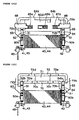
- This invention concerns an electromagnetic relay, and more specifically, the drive mechanism which makes and breaks the contacts of the relay.
- This relay comprises electromagnetic block 1, which is formed by wrapping coil 1c around two facing L-shaped cores, 1a and 1b; H-electrode 2b, which rotates shaft 2a on its axis in response to the presence or absence of excitation in electromagnetic block 1; transmission mechanism 3, which travels back and forth with the rotation of H electrode 2b; and contact mechanism 6, in which the movement of transmission mechanism 3 causes movable contacts 4a on members 4 to come in contact with or move away from fixed contacts 5a on members 5.
- contact mechanism 6 is driven by H electrode 2b and transmission mechanism 3, a scheme which requires a large number of components. This entails a large number of assembly processes and increases the likelihood that the precision with which the components are assembled, and hence the operating characteristics, will vary.
- H electrode 2b and contact mechanism 6 are arrayed in a linear fashion, which tends to increase the length of the relay. Since the length of contact mechanism 6 will increase with the number of circuits, it will be impossible to produce a short electromagnetic relay if there are a large number of circuits to make and break.
- An electromagnetic relay according to the preamble of claim 1 is known from DE 32 24 070 A.
- the objective of this invention is to provide an electromagnetic relay with fewer components so that it can be made shorter.
- H electrode and transmission mechanism are discrete components which are not assembled as a single piece and do not operate as a single component. For this reason they are liable to vary in assembly precision and operating characteristics, which will adversely affect the repeatability of their response.
- Another objective of this invention is to provide an electromagnetic relay whose assembly precision and operating characteristics will not vary and which will have a good response characteristic.
- the electromagnetic relay of this invention is as defined in claim 1.
- the aforesaid electromagnetic and movable blocks are enclosed in a box-shaped base block comprising two bases on whose exteriors are mounted the aforesaid contact mechanisms.
- the aforesaid bases should be identical in shape.
- the positions of the aforesaid electromagnetic and movable blocks should be adjustable within the aforesaid box-shaped base block in the axial direction of the aforesaid core so that the operating characteristics of the aforesaid contact mechanisms can be adjusted.
- the aforesaid contact mechanism comprises a number of pairs of movable and fixed contacts fitted into grooves in the exterior walls of the aforesaid box-shaped base. These contacts should act as partitions which touch the interior walls of the cover fitted onto the aforesaid base so that the walls are partitioned by each set of movable and fixed contacts.
- the aforesaid movable block engages with a member which is mounted on a card from which at least one drive rod protrudes to one side to drive the aforesaid contact mechanisms.
- the aforesaid movable block should comprise a permanent magnet sandwiched between two movable iron members.
- Two cut-away portions on the side of the aforesaid lower member should engage with two bosses on the internal surface of the aforesaid card.
- the aforesaid permanent magnet should engage between a pair of bosses on the internal surface of the aforesaid card.
- cut-away portions on the movable member on the upper end of the magnet should engage with tangs extending upward from the upper edge of the aforesaid card.
- the aforesaid movable block may be supported by two springs which engage with the ends of the card in such a way that the block is free to move back and forth in a course which is parallel to the axis of the aforesaid core.
- the exterior front edges of the card which come in contact with the inward-facing surfaces of the aforesaid supporting springs may be different distances from the center line of the card.
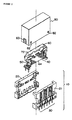
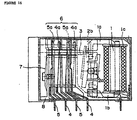
- the electromagnetic relay shown in Figure 1 is an embodiment of this invention. It comprises primarily of base block 10, electromagnetic block 40, movable block 60 and case cover 80.
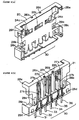
- Base block 10 is shaped roughly like a box and comprises of two halves, base unit 20 and base unit 21 (See Figure 6).
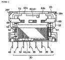
- Contact mechanisms 30 are installed on the exterior surfaces of the aforesaid base units 20 and 21. Since base units 20 and 21 are identical in shape, we shall omit a detailed explanation of base unit 20 for the sake of brevity.
- the exterior surface of base unit 21 is divided by partitions 22a and 22b into three parallel niches, 23a, 23b and 23c.
- Drive rods 65, 66 and 67 in movable block 60 which is shown in Figure 12 and will be discussed shortly, extend all the way to the innermost portions of niches 23a, 23b and 23c.
- At the lower ends of niches 23a, 23b and 23c are three pairs of slits, 25a through 25f, which communicate with the aforesaid niches 23a, 23b and 23c.
- Two indentations, 26a and 26b are provided on the upper portion of niche 23b.
- Two disconnected positioning ribs, 27a and 27b divide each of the aforesaid niches 23a, 23b and 23c down their center lines.
- Terminals 31a through 36a, on fixed contact elements 31, 33 and 36 and movable contact elements 32, 34 and 35, are pressed into slits 25a through 25f in base unit 21.
- fixed contact elements 31, 33 and 36 come in contact with and are held in position by ribs 27a and 27b on base unit 21; and their fixed contacts, 31b, 33b and 36b, are brought face to face with movable contacts 32b, 34b and 35b so that they can make or break contact with them.
- the contacts may be separated by force even if contact welding should occur.
- the three aforesaid pairs of ribs 27a and 27b are interposed between fixed contact elements 31, 33 and 36 and their respective movable contact elements 32, 34 and 35. This arrangement improves the isolation characteristic of the relay.
- fixed contact elements 31, 33 and 36 and movable contact elements 32, 34 and 35 can be pressed into various positions. This arrangement is convenient in that it allows the user to realize any of a number of different electromagnetic relays with various contact specifications.
- base units 20 and 21 have the same shape, there are fewer components to manage, a single mold will suffice, and economies can be realized in production costs.
- Electromagnetic block 40 is pictured in Figures 9 and 10.
- Coil 44 is wrapped around the central portion of spool 43, which is linearly symmetric.
- On either end of spool 43 are flanges 41 and 42.
- the ends of the coil which are drawn out are tied and soldered to coil terminals 45 on flange 41.
- Core 50 is inserted into center hole 46 of the aforesaid spool 43.
- Magnetic isolation plate 51, core support 52 and spring 53 are fitted, one after the other, onto one protruding end of the core and caulked in place.
- Core support 54, magnetic isolation plate 51 and spring 53 are fitted, one after the other, onto the other end of the core and caulked in place.
- springs 53 are fixed directly to electromagnetic block 40. This insures that the relay can be assembled with precision so that its operating characteristics will not vary.
- Magnetic isolation plate 51 and spring 53 are also secured at the same time that core support 52 is caulked in place. This reduces the number of assembly processes required.
- Magnetic isolation plate 51 comprises a thin plate of spring material in which hole 51a, which is to be used for caulking, has been punched. Its lower edge is bent at a right angle to form positioning stop 51b. Stop 51b engages with the lower surface of core support 52 to ensure that this support is mounted securely.
- Core supports 52 and 54 have a cross-shaped frontal surface. Arms 52a and 54a, which are used in the caulking process, project to either side of each support. The upper ends of the respective supports serve as magnetic poles 52b and 54b. Holes 52c and 54c, also used for caulking, are in the centers of the lower portions of the two supports.
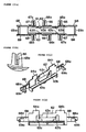
- Support springs 53 which can be seen in Figure 11, are stamped from a thin spring material which is then bent into shape. When the lower end of the spring is bent upward and folded upon itself, tab 53b, which will lock the bottom of the spring in position, projects beyond the lower edge of hole 53a, and caulking hole 53c is left open. Support springs 53 have two indentations 53e on their sides to allow them to engage with the other components.
- Movable block 60 which is shown in Figure 12, is formed by mounting on card 61, successively, L-shaped movable iron member 70 (first movable member), permanent magnet 71, which has the shape of a rectangular prism, and C-shaped movable iron member 72 (second movable member).
- Card 61 which is pictured in Figure 13, has two parallel side walls 62. On the inner surface of each wall is a pair of L-shaped projections, 63a and 63b. Tabs 64a and 64b project from the upper edges of both of the aforesaid walls 62. On the outer surface of each wall 62 are three drive rods, 65, 66 and 67, to drive the aforesaid movable contact elements 32, 34 and 35. Drive rods 65, 66 and 67 have, respectively, slits 65a, 66a and 67a, into which the movable contact elements can be pressed. Arms 68 extend in parallel from the ends of the aforesaid side walls 62. Ridges 69a and 69b, which traverse the ends of the card, come in contact with the aforesaid support springs 53. Recesses 68a face each other on the inner surfaces of the aforesaid arms 68.
- a cross section of one of the aforesaid ridges 69a and 69b would make linear contact with one of the aforesaid support springs 53.
- the inner edges of ridges 69a and 69b are equidistant form the center line of card 61.
- the loads on the two support springs 53 will vary when their angles of rotation vary, so the outer edges of ridges 69a and 69b will be different distances from the center line of card 61.
- first movable member 70 has two recesses 70c on its lateral edges between its two extremities, 70a and 70b.
- Permanent magnet 71 is of a length which allows it to fit in region 63c between the aforesaid projections 63a and 63b as shown in Figures 13 (c) and (d).
- Second movable member 72 has a projection 72c on the lateral surface of each of its ends. Between projections 72c it has two indentations, 72d and 72e, on its lateral surface.
- first movable member 70 When first movable member 70 is placed from above between side walls 62 on card 60, its recesses 70c engage with projections 63a and 63b on the inner surfaces of walls 62 to lock the member in place with respect to both its length and breadth.
- Second movable member 72 engages in recesses 68a on card 61.
- indentations 72d and 72e engage with tabs 64a and 64b on side walls 62, second movable member 72 is immobilized with respect to its length and height. This completes the assembly of movable block 60.
- This embodiment offers the advantage that permanent magnet 71 is securely fixed to card 61.
- electromagnetic block 40 and movable block 60 are mounted on the interior walls of base 20.
- Movable contact elements 32, 34 and 35 are pressed into slits 65a, 66a and 67a in drive rods 65, 66 and 67 on card 61, which project through windows 24a, 24b and 24c in the base unit.
- base units 20 and 21 are combined into a single unit and base block 10 is completed.
- arms 52a and 54a are able to travel slightly in the dimension of their length in through holes 28a and 28b.
- the contacts in contact mechanism 30 are separated by electromagnetic block 40 and movable block 60 with the help of base units 20 and 21. This arrangement insures that the electromagnetic relay will have a superior isolation characteristic.
- Case cover 80 has the form of a box which engages with base block 10 to enclose electromagnetic block 40 and movable block 60. It has two parallel ribs, 81a and 81b, on its interior surface. Even if cover 80 expands outward, ribs 81a and 81b are still engaged in indentations 26a and 26b in base units 20 and 21, so they will remain in contact with partitions 22a and 22b. For this reason the surface distance between niches 23a, 23b and 23c will increase and the isolation characteristic will improve.
- 82 are anchoring holes, and 83 are the anchors which go through them.
- partitions 22a and 22b on base units 20 and 21 and cover 80 are interposed between each pair of fixed and movable contact elements in contact mechanism 30. This arrangement insures that the isolation characteristic will be favorable.
- end segment 70b of first movable member 70 and end segment 72a of second movable member 72 are drawn to the aforesaid magnetic poles 54b and 52b by the magnetic force of permanent magnet 71 in opposition to the spring force of support springs 53.
- movable contacts 32b and 34b on contact elements 32 and 34 separate from fixed contacts 31b and 33b on elements 31 and 33, and movable contact 35b on contact element 35 moves over and touches fixed contact 36b on element 36.
- Movable contact 35b separates from fixed contact 36b, and movable contacts 32b and 34b make contact with fixed contacts 31b and 33b, thus switching all the contacts.
- Segment 70a on first movable member 70 is drawn to magnetic pole 52b of core support 52, and segment 72b on second movable member 72 is drawn to pole 54b of core support 54.
- the electromagnetic relay disclosed in claim 1 of this application has a movable block which fulfills the same function as the H electrode and the transmission mechanism in the example of the prior art.
- This invention requires fewer components. Fewer production processes are required, and no variation will occur in the precision with which the parts are assembled or the operating characteristics, as was the case with prior art relays.
- the contact mechanism is partitioned by the electromagnetic block and the movable block with the help of the base. This arrangement allows us to achieve an electromagnetic relay with a superior isolation characteristic.
- the box-shaped base block is formed from two base units.
- the mold used to form the aforesaid base has a simpler configuration than would be required to form an entire box-type base block and is easier to construct.
- the position of the electromagnetic block and the movable block may be adjusted by sliding them along the axial direction of the core. This changes the operating characteristics of the contact mechanism. Thus even if the load on the springs is altered when the combination of movable and fixed contact elements in the mechanism is changed, that load can be adjusted. Thus contact mechanisms with various specifications can be driven by the same electromagnetic block. Since the same components can be put to use for multiple purposes, parts control is simplified.
- the contact mechanism surrounded by the base on which the cover has been installed has a partition between each pair of movable and fixed contact elements. This design results in a contact mechanism with a superior isolation characteristic.
- the ribs on the cover make contact with the partitions on the aforesaid base. This has the effect of creating a longer surface between the neighboring pairs of contact elements already isolated by the base partitions, which further enhances the isolation characteristic of the relay.
- a movable block is installed on a card as one piece with a movable iron member.
- This movable block travels back and forth with its member in response to the presence or absence of excitation in the electromagnetic block, thus driving the contact mechanism.
- This arrangement eliminates variation in the precision with which the parts are assembled and the precision with which the relay operates. Also, the response characteristic is superior to that of prior art relays.
- the movable block is polarized to make it easier to achieve an electromagnetic relay with the desired operating specifications.
- the two movable iron members and the permanent magnet can be mounted on the card easily and with a high degree of precision.
Landscapes
- Physics & Mathematics (AREA)
- Electromagnetism (AREA)
- Switch Cases, Indication, And Locking (AREA)
- Electromagnets (AREA)
- Contacts (AREA)
Claims (11)
- Elektromagnetisches Relais, welches aufweist:wobei der bewegliche Block (60) mit einem Betätigungsstab (65, 66, 67) versehen ist, der aus einem in dem kastenförmigen Basisblock (40) ausgebildeten Fenster (24a, 24b, 24c) herausragt, wobei der Betätigungsstab (65, 66, 67) an dem beweglichen Kontakt (32b, 32b, 35b) des Kontaktmechanismus angreift.einen elektromagnetischen Block (40), der durch Wickeln einer Spule (44) um einen Kern (50) ausgebildet ist;einen beweglichen Block (60), der auf einem oberen Ende des elektromagnetischen Blocks (40) angeordnet ist und ein Eisenteil (70, 72) aufwiest, welches sich ansprechend auf eine Magnetisierung und Entmagnetisierung des elektromagnetischen Blocks parallel zum Kern (50) hin und her bewegt, wobei der bewegliche Block (60) an dem elektromagnetischen Block (40) durch Halterungsfedern (53) aufgehängt ist; undeinen Kontaktmechanismus (30) mit einem Festkontakt (31b, 33b, 36b) und einem durch eine Bewegung des beweglichen Blocks (60) betätigten beweglichen Kontakt (32b, 34b, 35b), welcher an einer Seite des elektromagnetischen Blocks (40) angebracht ist; gekennzeichnet durcheinen sowohl den elektromagnetischen Block (40) als auch den beweglichen Block (60) umschließenden kastenförmigen Basisblock (10), an dessen Außenseite der Kontaktmechanismus (30) angebracht ist,
- Elektromagnetisches Relais nach Anspruch 1, wobei der kastenförmige Basisblock (10) ein Paar von Basiseinheiten (20, 21) gleicher Form aufweist.
- Elektromagnetisches Relais nach Anspruch 1, wobei der Basisblock (10) eine Basiseinheit (20, 21) mit einer Abteilung zur Trennung eines Satzes aus zwei Kontaktelementen (31, 32; 33, 34; 35, 36) für den Festkontakt (31b, 33b, 36b) und den beweglichen Kontakt (32b, 34b, 35b) von anderen Sätzen aus zwei Kontaktelementen aufweist.
- Elektromagnetisches Relais nach Anspruch 3, wobei die Basiseinheit (20, 21) ferner eine Rippe (27a, 27b) zur Trennung des Satzes aus zwei Kontaktelementen aufweist.
- Elektromagnetisches Relais nach Anspruch 1, wobei der bewegliche Block (60) eine Karte (61) mit einem Betätigungsstab (65, 66, 67) zum Betätigen eines Kontaktelements (32, 34, 35) für den beweglichen Kontakt (32b, 34b, 35b) aufweist.
- Elektromagnetisches Relais nach Anspruch 5, wobei der bewegliche Block (60) ferner aufweist:ein erstes und zweites bewegliches Element (70, 72), welche durch die Magnetisierung des elektromagnetischen Blocks (10) betätigt werden; undeinen zwischen dem ersten und zweiten beweglichen Element (70, 72) liegenden Permanentmagneten (71).
- Elektromagnetisches Relais nach Anspruch 5, wobei eine Ausnehmung (70c) des ersten beweglichen Elements (70) einen Vorsprung (63a, 63b) auf einer Innenfläche der Karte (61) erfasst.
- Elektromagnetisches Relais nach Anspruch 5, wobei der Permanentmagnet (71) zwischen einem Paar von Vorsprüngen (63a, 63b) auf einer Innenfläche der Karte (61) festgesetzt ist.
- Elektromagnetisches Relais nach Anspruch 5, wobei der bewegliche Block (60) ferner eine Einsenkung (72d, 72e) des beweglichen Elements (72), die mit einem Lappen (64a, 64b) auf der Karte (61) in Eingriff ist, aufweist.
- Elektromagnetisches Relais nach Anspruch 5, wobei die Halterungsfedern (53) Enden der Karte (61) in einer solchen Weise erfassen, dass der bewegliche Block (60) parallel zu einer Achse des Kerns (50) in dem elektromagnetischen Block (40) frei hin und her gleiten kann.
- Elektromagnetisches Relais nach Anspruch 10, wobei ein Abstand zwischen einer mit einer der Halterungsfedern (53) in Berührung stehenden Rippe (69a) und der Mitte der Karte (61) von einem Abstand zwischen einer mit einer anderen der Halterungsfedern (53) in Berührung stehenden Rippe (69b) und der Mitte der Karte (61) verschieden ist.
Applications Claiming Priority (6)
| Application Number | Priority Date | Filing Date | Title |
|---|---|---|---|
| JP13179796 | 1996-05-27 | ||
| JP13179796A JP3596164B2 (ja) | 1996-05-27 | 1996-05-27 | 電磁継電器 |
| JP131797/96 | 1996-05-27 | ||
| JP13180996A JP3521616B2 (ja) | 1996-05-27 | 1996-05-27 | 電磁継電器 |
| JP131809/96 | 1996-05-27 | ||
| JP13180996 | 1996-05-27 |
Publications (3)
| Publication Number | Publication Date |
|---|---|
| EP0810620A2 EP0810620A2 (de) | 1997-12-03 |
| EP0810620A3 EP0810620A3 (de) | 2000-11-02 |
| EP0810620B1 true EP0810620B1 (de) | 2005-03-30 |
Family
ID=26466532
Family Applications (1)
| Application Number | Title | Priority Date | Filing Date |
|---|---|---|---|
| EP97108516A Expired - Lifetime EP0810620B1 (de) | 1996-05-27 | 1997-05-27 | Elektromagnetisches Relais |
Country Status (4)
| Country | Link |
|---|---|
| US (1) | US5880654A (de) |
| EP (1) | EP0810620B1 (de) |
| CN (1) | CN1107332C (de) |
| DE (1) | DE69732876T2 (de) |
Families Citing this family (9)
| Publication number | Priority date | Publication date | Assignee | Title |
|---|---|---|---|---|
| US8193881B2 (en) * | 2007-09-14 | 2012-06-05 | Fujitsu Component Limited | Relay |
| EP3059754B1 (de) * | 2009-06-23 | 2022-03-09 | Panasonic Intellectual Property Management Co., Ltd. | Elektromagnetisches relais |
| JP5741338B2 (ja) * | 2011-09-15 | 2015-07-01 | オムロン株式会社 | 端子部材のシール構造、及び、電磁継電器 |
| CN104701087B (zh) * | 2015-01-14 | 2017-07-21 | 宁波世通电子科技有限公司 | 一种用于大电流环境的继电器 |
| JP6631068B2 (ja) * | 2015-07-27 | 2020-01-15 | オムロン株式会社 | 接点機構およびこれを用いた電磁継電器 |
| DE102016211931B4 (de) * | 2016-06-30 | 2023-03-16 | Te Connectivity Germany Gmbh | Leistungsschütz mit hoher mechanischer Schockfestigkeit |
| CN107437481B (zh) * | 2017-09-05 | 2020-01-17 | 三友联众集团股份有限公司 | 一种用于磁保持继电器的磁路系统 |
| CN107464726B (zh) * | 2017-09-05 | 2019-11-29 | 三友联众集团股份有限公司 | 一种衔铁滑动式磁保持继电器 |
| CN107644786A (zh) * | 2017-11-03 | 2018-01-30 | 三友联众集团股份有限公司 | 一种推片限位式继电器 |
Family Cites Families (6)
| Publication number | Priority date | Publication date | Assignee | Title |
|---|---|---|---|---|
| DE3224070C2 (de) * | 1982-06-28 | 1986-02-20 | Siemens AG, 1000 Berlin und 8000 München | Polarisiertes Relais |
| US4587502A (en) * | 1983-04-23 | 1986-05-06 | Omron Tateisi Electronics Co. | Electromagnetic relay |
| DE3417891C1 (de) * | 1984-05-14 | 1985-08-14 | Sds-Elektro Gmbh, 8024 Deisenhofen | Elektromagnetisches Schaltgeraet |
| US4740771A (en) * | 1986-08-26 | 1988-04-26 | Matsushita Electric Works, Ltd. | Armature biasing means in an electromagnetic relay |
| ATA258388A (de) * | 1988-10-19 | 2000-02-15 | Schrack Components Ag | Relais mit einem einen luftspalt aufweisenden, im wesentlichen ebenen und rechteckig gestalteten magnetgestell |
| AT399417B (de) * | 1993-07-02 | 1995-05-26 | Schrack Components Ag | Relais |
-
1997
- 1997-05-27 EP EP97108516A patent/EP0810620B1/de not_active Expired - Lifetime
- 1997-05-27 DE DE69732876T patent/DE69732876T2/de not_active Expired - Lifetime
- 1997-05-27 CN CN97113191.0A patent/CN1107332C/zh not_active Expired - Fee Related
- 1997-05-27 US US08/863,784 patent/US5880654A/en not_active Expired - Lifetime
Also Published As
| Publication number | Publication date |
|---|---|
| DE69732876T2 (de) | 2006-04-06 |
| US5880654A (en) | 1999-03-09 |
| CN1167996A (zh) | 1997-12-17 |
| DE69732876D1 (de) | 2005-05-04 |
| CN1107332C (zh) | 2003-04-30 |
| EP0810620A3 (de) | 2000-11-02 |
| EP0810620A2 (de) | 1997-12-03 |
Similar Documents
| Publication | Publication Date | Title |
|---|---|---|
| EP2031624B1 (de) | Polarisiertes elektromagnetisches Relais und Spulenanordnung | |
| EP0810620B1 (de) | Elektromagnetisches Relais | |
| EP0817230B1 (de) | Elektromagnetischer Schalter | |
| US5473297A (en) | Electromagnetic relay | |
| US6043730A (en) | Electromagnetic actuator | |
| KR0129533B1 (ko) | 케이지에 의해 보유되는 영구 자석을 갖는 전자석 | |
| JPS6326920A (ja) | 電磁継電器 | |
| JPS6355176B2 (de) | ||
| JP3596164B2 (ja) | 電磁継電器 | |
| JP3521616B2 (ja) | 電磁継電器 | |
| JP3809666B2 (ja) | 電磁継電器 | |
| JP3707076B2 (ja) | 電磁継電器 | |
| JP2861413B2 (ja) | 有極電磁石 | |
| JPH075609Y2 (ja) | 有極電磁継電器 | |
| JPH0436534Y2 (de) | ||
| JPH0422527Y2 (de) | ||
| JPH0231717Y2 (de) | ||
| JP4186034B2 (ja) | 電磁継電器 | |
| JP2566387B2 (ja) | 有極リレー | |
| JPS6355741B2 (de) | ||
| JPH0731971B2 (ja) | 電気機器の基台 | |
| JPH0260021A (ja) | 電磁継電器 | |
| JPH0755793Y2 (ja) | 電磁継電器 | |
| EP0167131A2 (de) | Elektromagnetisches Relais | |
| JPS6022535Y2 (ja) | 電磁継電器 |
Legal Events
| Date | Code | Title | Description |
|---|---|---|---|
| PUAI | Public reference made under article 153(3) epc to a published international application that has entered the european phase |
Free format text: ORIGINAL CODE: 0009012 |
|
| 17P | Request for examination filed |
Effective date: 19970620 |
|
| AK | Designated contracting states |
Kind code of ref document: A2 Designated state(s): DE FR GB IT |
|
| PUAL | Search report despatched |
Free format text: ORIGINAL CODE: 0009013 |
|
| AK | Designated contracting states |
Kind code of ref document: A3 Designated state(s): DE FR GB IT |
|
| 17Q | First examination report despatched |
Effective date: 20030623 |
|
| GRAP | Despatch of communication of intention to grant a patent |
Free format text: ORIGINAL CODE: EPIDOSNIGR1 |
|
| GRAS | Grant fee paid |
Free format text: ORIGINAL CODE: EPIDOSNIGR3 |
|
| GRAA | (expected) grant |
Free format text: ORIGINAL CODE: 0009210 |
|
| AK | Designated contracting states |
Kind code of ref document: B1 Designated state(s): DE FR GB IT |
|
| REG | Reference to a national code |
Ref country code: GB Ref legal event code: FG4D |
|
| REF | Corresponds to: |
Ref document number: 69732876 Country of ref document: DE Date of ref document: 20050504 Kind code of ref document: P |
|
| PG25 | Lapsed in a contracting state [announced via postgrant information from national office to epo] |
Ref country code: IT Free format text: LAPSE BECAUSE OF NON-PAYMENT OF DUE FEES Effective date: 20050527 |
|
| PLBE | No opposition filed within time limit |
Free format text: ORIGINAL CODE: 0009261 |
|
| STAA | Information on the status of an ep patent application or granted ep patent |
Free format text: STATUS: NO OPPOSITION FILED WITHIN TIME LIMIT |
|
| ET | Fr: translation filed | ||
| 26N | No opposition filed |
Effective date: 20060102 |
|
| PGRI | Patent reinstated in contracting state [announced from national office to epo] |
Ref country code: IT Effective date: 20091201 |
|
| PGFP | Annual fee paid to national office [announced via postgrant information from national office to epo] |
Ref country code: FR Payment date: 20100603 Year of fee payment: 14 |
|
| PGFP | Annual fee paid to national office [announced via postgrant information from national office to epo] |
Ref country code: IT Payment date: 20100524 Year of fee payment: 14 Ref country code: DE Payment date: 20100531 Year of fee payment: 14 |
|
| PGFP | Annual fee paid to national office [announced via postgrant information from national office to epo] |
Ref country code: GB Payment date: 20100513 Year of fee payment: 14 |
|
| REG | Reference to a national code |
Ref country code: DE Ref legal event code: R119 Ref document number: 69732876 Country of ref document: DE |
|
| REG | Reference to a national code |
Ref country code: DE Ref legal event code: R119 Ref document number: 69732876 Country of ref document: DE |
|
| GBPC | Gb: european patent ceased through non-payment of renewal fee |
Effective date: 20110527 |
|
| REG | Reference to a national code |
Ref country code: FR Ref legal event code: ST Effective date: 20120131 |
|
| PG25 | Lapsed in a contracting state [announced via postgrant information from national office to epo] |
Ref country code: IT Free format text: LAPSE BECAUSE OF NON-PAYMENT OF DUE FEES Effective date: 20110527 |
|
| PG25 | Lapsed in a contracting state [announced via postgrant information from national office to epo] |
Ref country code: FR Free format text: LAPSE BECAUSE OF NON-PAYMENT OF DUE FEES Effective date: 20110531 |
|
| PG25 | Lapsed in a contracting state [announced via postgrant information from national office to epo] |
Ref country code: GB Free format text: LAPSE BECAUSE OF NON-PAYMENT OF DUE FEES Effective date: 20110527 |
|
| REG | Reference to a national code |
Ref country code: DE Ref legal event code: R082 Ref document number: 69732876 Country of ref document: DE Representative=s name: KILIAN KILIAN & PARTNER MBB PATENTANWAELTE, DE Ref country code: DE Ref legal event code: R082 Ref document number: 69732876 Country of ref document: DE Representative=s name: KILIAN KILIAN & PARTNER, DE |
|
| PG25 | Lapsed in a contracting state [announced via postgrant information from national office to epo] |
Ref country code: DE Free format text: LAPSE BECAUSE OF NON-PAYMENT OF DUE FEES Effective date: 20111130 |