EP0810657A2 - Dissipateur de chaleur avec accélérateur de refroidissement - Google Patents
Dissipateur de chaleur avec accélérateur de refroidissement Download PDFInfo
- Publication number
- EP0810657A2 EP0810657A2 EP97303678A EP97303678A EP0810657A2 EP 0810657 A2 EP0810657 A2 EP 0810657A2 EP 97303678 A EP97303678 A EP 97303678A EP 97303678 A EP97303678 A EP 97303678A EP 0810657 A2 EP0810657 A2 EP 0810657A2
- Authority
- EP
- European Patent Office
- Prior art keywords
- insert
- heat sink
- pipes
- heat
- liquid cooled
- Prior art date
- Legal status (The legal status is an assumption and is not a legal conclusion. Google has not performed a legal analysis and makes no representation as to the accuracy of the status listed.)
- Withdrawn
Links
Images
Classifications
-
- H—ELECTRICITY
- H10—SEMICONDUCTOR DEVICES; ELECTRIC SOLID-STATE DEVICES NOT OTHERWISE PROVIDED FOR
- H10W—GENERIC PACKAGES, INTERCONNECTIONS, CONNECTORS OR OTHER CONSTRUCTIONAL DETAILS OF DEVICES COVERED BY CLASS H10
- H10W40/00—Arrangements for thermal protection or thermal control
- H10W40/40—Arrangements for thermal protection or thermal control involving heat exchange by flowing fluids
- H10W40/47—Arrangements for thermal protection or thermal control involving heat exchange by flowing fluids by flowing liquids, e.g. forced water cooling
-
- F—MECHANICAL ENGINEERING; LIGHTING; HEATING; WEAPONS; BLASTING
- F28—HEAT EXCHANGE IN GENERAL
- F28F—DETAILS OF HEAT-EXCHANGE AND HEAT-TRANSFER APPARATUS, OF GENERAL APPLICATION
- F28F1/00—Tubular elements; Assemblies of tubular elements
- F28F1/10—Tubular elements and assemblies thereof with means for increasing heat-transfer area, e.g. with fins, with projections, with recesses
- F28F1/12—Tubular elements and assemblies thereof with means for increasing heat-transfer area, e.g. with fins, with projections, with recesses the means being only outside the tubular element
- F28F1/14—Tubular elements and assemblies thereof with means for increasing heat-transfer area, e.g. with fins, with projections, with recesses the means being only outside the tubular element and extending longitudinally
- F28F1/22—Tubular elements and assemblies thereof with means for increasing heat-transfer area, e.g. with fins, with projections, with recesses the means being only outside the tubular element and extending longitudinally the means having portions engaging further tubular elements
-
- F—MECHANICAL ENGINEERING; LIGHTING; HEATING; WEAPONS; BLASTING
- F28—HEAT EXCHANGE IN GENERAL
- F28F—DETAILS OF HEAT-EXCHANGE AND HEAT-TRANSFER APPARATUS, OF GENERAL APPLICATION
- F28F13/00—Arrangements for modifying heat-transfer, e.g. increasing, decreasing
- F28F13/06—Arrangements for modifying heat-transfer, e.g. increasing, decreasing by affecting the pattern of flow of the heat-exchange media
-
- F—MECHANICAL ENGINEERING; LIGHTING; HEATING; WEAPONS; BLASTING
- F28—HEAT EXCHANGE IN GENERAL
- F28D—HEAT-EXCHANGE APPARATUS, NOT PROVIDED FOR IN ANOTHER SUBCLASS, IN WHICH THE HEAT-EXCHANGE MEDIA DO NOT COME INTO DIRECT CONTACT
- F28D21/00—Heat-exchange apparatus not covered by any of the groups F28D1/00 - F28D20/00
- F28D2021/0019—Other heat exchangers for particular applications; Heat exchange systems not otherwise provided for
- F28D2021/0028—Other heat exchangers for particular applications; Heat exchange systems not otherwise provided for for cooling heat generating elements, e.g. for cooling electronic components or electric devices
- F28D2021/0029—Heat sinks
Definitions
- the present invention relates in general to heat sinks, and more particularly to a liquid cooled heat sink with coolant accelerator.
- Liquid cooled heat sinks are known in the prior art for removing heat from electronic components.
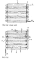
- One such liquid cooled heat sink is illustrated in Fig. 1(a).
- This heat sink typically comprises an aluminium block 1 incorporating a tube channel 3 which winds it way several times through the heat sink.
- the temperature of the cooling liquid increases as it passes through the serpentine channel 3, picking up heat from the electronic components being cooled. This results in uneven cooling and lower life expectancy of the components towards the end of the serpentine channel 3.
- a liquid cooled heat sink for removing unwanted heat from a heat source, comprising:
- the parallel flow arrangement according to the present invention must provide the same average fluid velocity in each of the parallel paths. Since volumetric flow rate is determined by the pump system (i.e. a constant flow rate), each parallel path receives only a fraction of the liquid flow which is supplied to the heat sink. Therefore, the cross-sectional area of each of the parallel paths must be adjusted to compensate for the lower flow rate.
- the insert or accelerator of the present invention is provided in each of the parallel flow paths for accelerating the flow of cooling liquid, thereby enhancing thermal performance of the heat sink.
- the heat sink of the present invention comprises a front end header 5, a rear end header 7, a plurality of parallel tube channels 9 connected to the headers 5 and 7 and housing within a thermally conductive block 11.
- each parallel tube 9 is preferably provided with an insert or accelerator 13 for blocking part of the fluid flow and thereby increasing velocity within the channel tube 9.
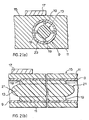
- the channel tube 9 is shown disposed within thermally conductive block 11.
- a surface 15 of the block 11 is in contact with a plurality of heat generating electronic devices, shown schematically in Figs. 2(a) and 2(b) by reference numeral 17.
- the block 11 is an aluminium block into which copper tube 9 is inserted and expanded using conventional techniques.
- the insert 13 is shown as being of generally cylindrical shape and is secured within the copper tube 9 via interference fit by means of a plurality of ribs 19. Opposite ends 21 of the insert 13 are preferably of conical shape.
- the insert 13 may be fabricated from plastic or other suitable material.
- the insert 13 causes fluid flow to accelerate around an annulus between the inside surface 23 of the copper tube and the outside of the insert or accelerator 13, thereby increasing the velocity of fluid flow. Therefore, considered one way, by keeping a constant diameter of tube 9, the provision of insert 13 increases by velocity of fluid flow, thereby enhancing the heat transfer characteristics relative to a tube of similar diameter without an insert. Or, considered an another way, by enlarging the diameter of the copper tube 9, and providing insert 13 to maintain a fluid flow which is similar to the fluid flow of a smaller diameter tube without an insert, the heat transfer surface area is thereby increased, thus improving overall thermal performance.
- the insert 13 may also be used to increase the surface area of heat transfer by enlarging the channel diameter and maintaining the same average velocity as would characterise a lesser diameter channel.
- An analytical investigation has been conducted to study this aspect of operation, based on the following assumption: constant volumetric flow rate, constant cross-sectional flow area (maintained constant by enlarging the channel diameter (D) and choosing an appropriate insert diameter (X)), smooth channel surface, and correlation for the friction factor in the range 4000 ⁇ Reynolds no. ⁇ 200000 for head loss calculations. The result of this investigation are reproduced in Table 2.
- Table 2 Effect of Insert Due to Increase in Surface Increase In X/D Velocity Conductance Head Loss 0.5 1.15 1.21 1.96 0.7 1.40 1.44 2.90
- Table 2 illustrates that utilising insert 13 for the sake of increasing the surface area and keeping the flow rate the same as would be provided with a lesser diameter tube channel, results in less significant head loss increases than shown in Table 1.
- Table 2 implies that by increasing the channel diameter (D) to 1.4 times its original diameter and incorporating a 0.7 insert, a 44% increase in conductance can be realised compromised by a 190% increase in head loss.
- the thickness of tube 9 is 0.049 inches
- the diameter of insert 13 is 0.342 inches
- the diameter of tube channel 9 is 0.521 inches
- the thickness of each rib 19 is 0.040 inches. This results in a cross-sectional area of the insert 13 being 0.1062in 2 and a cross-sectional area of the tube 9 being 0.2132in 2 .
- the preferred length of the insert 13 within channel tube 9 is equal to the length of the conductive block 11 parallel to the tube(s) 9, although for manufacturing reasons the insert may in fact be approximately 2" shorter than the imbedded tube 9, approximately 1" set back from each end.
Landscapes
- Engineering & Computer Science (AREA)
- Physics & Mathematics (AREA)
- Thermal Sciences (AREA)
- Mechanical Engineering (AREA)
- General Engineering & Computer Science (AREA)
- Geometry (AREA)
- Cooling Or The Like Of Semiconductors Or Solid State Devices (AREA)
- Particle Accelerators (AREA)
Applications Claiming Priority (2)
| Application Number | Priority Date | Filing Date | Title |
|---|---|---|---|
| US65651396A | 1996-05-31 | 1996-05-31 | |
| US656513 | 1996-05-31 |
Publications (2)
| Publication Number | Publication Date |
|---|---|
| EP0810657A2 true EP0810657A2 (fr) | 1997-12-03 |
| EP0810657A3 EP0810657A3 (fr) | 1999-09-15 |
Family
ID=24633349
Family Applications (1)
| Application Number | Title | Priority Date | Filing Date |
|---|---|---|---|
| EP97303678A Withdrawn EP0810657A3 (fr) | 1996-05-31 | 1997-06-02 | Dissipateur de chaleur avec accélérateur de refroidissement |
Country Status (2)
| Country | Link |
|---|---|
| EP (1) | EP0810657A3 (fr) |
| CA (1) | CA2203213A1 (fr) |
Cited By (5)
| Publication number | Priority date | Publication date | Assignee | Title |
|---|---|---|---|---|
| DE19831282A1 (de) * | 1998-07-13 | 2000-01-20 | Abb Daimler Benz Transp | Halbleiterkühlkörper-System und Verfahren zur Herstellung |
| CN101947474A (zh) * | 2010-07-21 | 2011-01-19 | 北京航空航天大学 | 一种分级供液温度自补偿液氦热沉结构 |
| ITTO20090946A1 (it) * | 2009-12-01 | 2011-06-02 | Varian Spa | Metodo per migliorare l efficienza di scambio termico fra un corpo metallico ed un tubo in cui scorre un fluido di scambio termico. |
| US9022101B2 (en) | 2009-12-18 | 2015-05-05 | Vacon Oyj | Arrangement in a liquid cooler |
| EP3118468A1 (fr) * | 2015-07-14 | 2017-01-18 | Institute of Science and Technology Austria | Re-laminarisation d'un écoulement turbulent dans un conduit |
Family Cites Families (8)
| Publication number | Priority date | Publication date | Assignee | Title |
|---|---|---|---|---|
| GB981148A (en) * | 1962-10-11 | 1965-01-20 | Oerlikon Maschf | Improvements in high-current rectifier installations |
| GB1238462A (fr) * | 1967-07-11 | 1971-07-07 | ||
| DE3325230C2 (de) * | 1983-07-13 | 1994-03-31 | Schilling Heinz Kg | Wasser/Sole-Luft-Wärmetauscher |
| JPS61222242A (ja) * | 1985-03-28 | 1986-10-02 | Fujitsu Ltd | 冷却装置 |
| DE8804742U1 (de) * | 1988-04-11 | 1988-06-09 | Siemens AG, 1000 Berlin und 8000 München | Kühlkörper mit eingesetztem Füllstück zur Kühlung eines elektrischen Bauelementes mit einem flüssigen Kühlmedium |
| DE3908401A1 (de) * | 1989-03-15 | 1990-09-20 | Ruhrgas Ag | Verfahren und einrichtung zum gleichrichten einer gestoerten stroemung |
| DE4421025C2 (de) * | 1994-06-16 | 1999-09-09 | Abb Patent Gmbh | Kühlkörper mit mindestens einem Kühlkanal |
| FR2729044B1 (fr) * | 1994-12-30 | 1997-01-24 | Atherm | Element refroisisseur et connecteur pour un composant electronique de puissance refroidi par un fluide electriquement isole du composant |
-
1997
- 1997-04-21 CA CA002203213A patent/CA2203213A1/fr not_active Abandoned
- 1997-06-02 EP EP97303678A patent/EP0810657A3/fr not_active Withdrawn
Cited By (6)
| Publication number | Priority date | Publication date | Assignee | Title |
|---|---|---|---|---|
| DE19831282A1 (de) * | 1998-07-13 | 2000-01-20 | Abb Daimler Benz Transp | Halbleiterkühlkörper-System und Verfahren zur Herstellung |
| ITTO20090946A1 (it) * | 2009-12-01 | 2011-06-02 | Varian Spa | Metodo per migliorare l efficienza di scambio termico fra un corpo metallico ed un tubo in cui scorre un fluido di scambio termico. |
| US8646178B2 (en) | 2009-12-01 | 2014-02-11 | Agilent Technologies, Inc. | Heat exchanger fabrication with improved thermal exchange efficiency |
| US9022101B2 (en) | 2009-12-18 | 2015-05-05 | Vacon Oyj | Arrangement in a liquid cooler |
| CN101947474A (zh) * | 2010-07-21 | 2011-01-19 | 北京航空航天大学 | 一种分级供液温度自补偿液氦热沉结构 |
| EP3118468A1 (fr) * | 2015-07-14 | 2017-01-18 | Institute of Science and Technology Austria | Re-laminarisation d'un écoulement turbulent dans un conduit |
Also Published As
| Publication number | Publication date |
|---|---|
| EP0810657A3 (fr) | 1999-09-15 |
| CA2203213A1 (fr) | 1997-11-30 |
Similar Documents
| Publication | Publication Date | Title |
|---|---|---|
| US3220471A (en) | Heat transfer | |
| US5005640A (en) | Isothermal multi-passage cooler | |
| US6148906A (en) | Flat plate heat pipe cooling system for electronic equipment enclosure | |
| US5960861A (en) | Cold plate design for thermal management of phase array-radar systems | |
| US6269002B1 (en) | Heat sink with flow guide | |
| US6935409B1 (en) | Cooling apparatus having low profile extrusion | |
| US5020586A (en) | Air-cooled heat exchanger for electronic circuit modules | |
| US4777561A (en) | Electronic module with self-activated heat pipe | |
| US5829516A (en) | Liquid cooled heat sink for cooling electronic components | |
| US4675783A (en) | Heat pipe heat sink for semiconductor devices | |
| US5844333A (en) | Device and method for cooling a motor | |
| US4928756A (en) | Heat dissipating fin and method for making fin assembly | |
| US5424916A (en) | Combination conductive and convective heatsink | |
| KR0182794B1 (ko) | 공압적으로 연결된 히트 싱크 조립체 | |
| US4633371A (en) | Heat pipe heat exchanger for large scale integrated circuits | |
| EP0514141A1 (fr) | Appareil de transfert de chaleur | |
| US20230247797A1 (en) | Heat dissipating structure | |
| US3406753A (en) | Peg type heat exchangers for thermoelectric devices | |
| CA2287682A1 (fr) | Echangeur de chaleur a ventilateur arriere a haut rendement | |
| JP2020107885A (ja) | 流体分配メカニズムを有するフレキシブルな冷却板 | |
| US20220071056A1 (en) | Liquid cooling device and manufacturing method thereof | |
| MY127387A (en) | Heat exchanger | |
| CA2203213A1 (fr) | Puits de chaleur avec accelerateur de debit de liquide de refroidissement | |
| US5995367A (en) | Heat exchanger having an extruded, tiered heat sink | |
| WO2007024229A1 (fr) | Echangeur thermique destine a des applications thermoelectriques |
Legal Events
| Date | Code | Title | Description |
|---|---|---|---|
| PUAI | Public reference made under article 153(3) epc to a published international application that has entered the european phase |
Free format text: ORIGINAL CODE: 0009012 |
|
| AK | Designated contracting states |
Kind code of ref document: A2 Designated state(s): AT BE CH DE DK ES FI FR GB GR IE IT LI LU MC NL PT SE |
|
| PUAL | Search report despatched |
Free format text: ORIGINAL CODE: 0009013 |
|
| AK | Designated contracting states |
Kind code of ref document: A3 Designated state(s): AT BE CH DE DK ES FI FR GB GR IE IT LI LU MC NL PT SE |
|
| AKX | Designation fees paid |
Free format text: AT BE CH DE DK ES FI FR GB GR IE IT LI LU MC NL PT SE |
|
| STAA | Information on the status of an ep patent application or granted ep patent |
Free format text: STATUS: THE APPLICATION IS DEEMED TO BE WITHDRAWN |
|
| 18D | Application deemed to be withdrawn |
Effective date: 20000105 |