EP0810949B1 - Eimer - Google Patents
Eimer Download PDFInfo
- Publication number
- EP0810949B1 EP0810949B1 EP96901204A EP96901204A EP0810949B1 EP 0810949 B1 EP0810949 B1 EP 0810949B1 EP 96901204 A EP96901204 A EP 96901204A EP 96901204 A EP96901204 A EP 96901204A EP 0810949 B1 EP0810949 B1 EP 0810949B1
- Authority
- EP
- European Patent Office
- Prior art keywords
- bucket
- shaped handle
- lid
- handle
- shaped
- Prior art date
- Legal status (The legal status is an assumption and is not a legal conclusion. Google has not performed a legal analysis and makes no representation as to the accuracy of the status listed.)
- Expired - Lifetime
Links
Images




Classifications
-
- B—PERFORMING OPERATIONS; TRANSPORTING
- B65—CONVEYING; PACKING; STORING; HANDLING THIN OR FILAMENTARY MATERIAL
- B65D—CONTAINERS FOR STORAGE OR TRANSPORT OF ARTICLES OR MATERIALS, e.g. BAGS, BARRELS, BOTTLES, BOXES, CANS, CARTONS, CRATES, DRUMS, JARS, TANKS, HOPPERS, FORWARDING CONTAINERS; ACCESSORIES, CLOSURES, OR FITTINGS THEREFOR; PACKAGING ELEMENTS; PACKAGES
- B65D25/00—Details of other kinds or types of rigid or semi-rigid containers
- B65D25/28—Handles
- B65D25/2867—Handles with respective ends fixed to local areas of two opposite sides or wall-part
-
- B—PERFORMING OPERATIONS; TRANSPORTING
- B65—CONVEYING; PACKING; STORING; HANDLING THIN OR FILAMENTARY MATERIAL
- B65D—CONTAINERS FOR STORAGE OR TRANSPORT OF ARTICLES OR MATERIALS, e.g. BAGS, BARRELS, BOTTLES, BOXES, CANS, CARTONS, CRATES, DRUMS, JARS, TANKS, HOPPERS, FORWARDING CONTAINERS; ACCESSORIES, CLOSURES, OR FITTINGS THEREFOR; PACKAGING ELEMENTS; PACKAGES
- B65D2525/00—Details of other kinds or types of rigid or semi-rigid containers
- B65D2525/28—Handles
- B65D2525/281—Details relating to handles
- B65D2525/284—Details relating to handles combined with closure retaining means
-
- B—PERFORMING OPERATIONS; TRANSPORTING
- B65—CONVEYING; PACKING; STORING; HANDLING THIN OR FILAMENTARY MATERIAL
- B65D—CONTAINERS FOR STORAGE OR TRANSPORT OF ARTICLES OR MATERIALS, e.g. BAGS, BARRELS, BOTTLES, BOXES, CANS, CARTONS, CRATES, DRUMS, JARS, TANKS, HOPPERS, FORWARDING CONTAINERS; ACCESSORIES, CLOSURES, OR FITTINGS THEREFOR; PACKAGING ELEMENTS; PACKAGES
- B65D2525/00—Details of other kinds or types of rigid or semi-rigid containers
- B65D2525/28—Handles
- B65D2525/281—Details relating to handles
- B65D2525/286—Details relating to handles movable between two or more stable positions, e.g. a retracted and an extended position
- B65D2525/287—Details relating to handles movable between two or more stable positions, e.g. a retracted and an extended position by sliding action
Definitions
- the present invention is concerned with a bucket that children cannot put over their head, and more precisely with a bucket for use in putting away toy construction blocks.
- the object of the present invention to provide a bucket which is simple to manufacture, which would be stackable, and which has a reduced opening so that children cannot put it over their head, while offering as much storage space as regular buckets.
- the bucket comprises:
- the invention is characterized in that the U-shaped handle is non-pivoting and has opposite side legs slidably mounted onto the side walls and stopping means for reducing sliding of the handle between a first position where the U-shaped handle bears against the lid when the same is fitted in the circumscribing edges and a second position where the U-shaped handle extends away from the lid and thus makes it possible to remove the lid from the circumscribing edges, whereby the U-shaped handle both in first and second positions divides the opening into two smaller openings, thereby preventing children from putting the bucket over their head.
- the bucket further comprises blocking means for keeping still the U-shaped handle in the second position whereby easing removal of the lid.
- the removable lid may have toy blocks coupling elements projecting outwardly therefrom and the bucket is made of plastic material.
- the bucket further comprises a transversal recess in the bottom wall, and the handle is sized and shaped to fit into the transversal recess of another identical stackable bucket superposed onto the bucket, whereby the buckets are stackable.
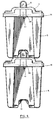
- the stackable bucket 1 has a bottom wall 3, a set of side walls 5, a removable lid 7 and a U-shaped handle 9.
- the side walls 5 project upwardly from the bottom wall 3 and form an opening 15 having circumscribing edges 16, as shown on Figures 1, 2 and 3.
- Each of the circumscribing edges 16 defines an inner flange 17 and an outer flange 19.
- the bottom wall 3, the side walls 5 and the inner and outer flanges 17 and 19 are tapered to lodge in other identical buckets, before the U-shaped handle is mounted.
- the removable lid 7 fits in the circumscribing edges 16, and more particularly in the inner flanges 17 defined by the circumscribing edges 16 which act as a support for the lid 7.
- the lid 7 comprises a pair of opposing lips 23, shown on Figures 9 and 10 and each of the inner flanges 17 adjacent to the opposing lips 23 may further comprise two grasping recesses 21, and located so that the grasping recesses 21 are under the opposite lips 23.
- the opposite lips 23 and the grasping recesses 21 allow a user to insert his fingers between one opposite lip 23 and the grasping recess 21 underneath, to easily remove the lid 7 from the bucket.
- the removable lid 7 preferably has toy blocks coupling elements 25 that project outwardly therefrom and are shaped to receive small corresponding toy blocks (not shown).
- the toy blocks coupling elements are small coupling elements, disposed in three strips 27.
- the exterior strips have four rows and twenty-four columns, and the middle strip has twelve rows and twenty four columns.
- the toy block coupling elements are large coupling elements, disposed in three strips 27.
- the exterior strips have two rows and twelve columns and the middle strip has six rows and twelve columns.
- the middle strip is progressively raised with respect to the exterior strips to avoid sharp edges, thus reducing danger for children.
- the bucket disclosed hereinabove is also provided with a non-pivoting U-shaped handle 9, shown on Figures 4, 5 and 11.
- the handle 9 has opposite side legs 31 slidably mounted onto opposite side walls 5, and more precisely in grooves 33 made through opposite outer flanges 19, shown on Figures 3 and 8.
- the grooves 33 are shaped to receive the legs 31 of the U-shaped handle 9.
- the handle 9 also has stopping means 39 for limiting sliding of the handle 9 between a first position, shown on Figures 4 and 6, where the U-shaped handle 9 bears against the lid 7 when the same is fitted in the circumscribing edges 16, and a second position (not shown) where the U-shaped handle 9 extends away from the lid 7 and thus makes it possible to remove the lid 7 from the circumscribing edges 16.
- the first and second positions of the handle 9 are determined in such a manner that the handle 7 constantly divides the opening 15 into two smaller openings.
- the two smaller openings are sized small enough so that a child cannot insert his head in the two smaller openings, thus prevents him from putting his head into the bucket where it could get stuck.
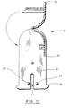
- the stopping means 39 are shown on Figures 4, 6 and 11. It consists, for example, of a pair of hooks at the extremity of each leg 31 of the U-shaped handle 9. The hooks point externally and make the extremities of the U-shaped handle 9 larger than the grooves 33, thus stopping the sliding of the U-shaped handle 9 in the second position.
- the U-shaped handle 9 further comprises, on each extremity of the legs 31 a central slot 41. By pressing the sides of the extremity of one of the legs 31, the central slot 41 therein allows reduction of the width of the leg 31 and its insertion in the corresponding groove 33.
- FIG 11 shows the handle 9 disassembled
- the handle 9 has a closed reversed half-elliptic cross section.
- the handle has two ribs 35 downwardly projecting from the reversed half-elliptic cross section for fixing horizontally the handle 9 when the handle 9 is pressed against the lid 7.
- the two ribs are sized and shaped for tightly fitting between the toy blocks coupling elements 25 of the lid 7, thereby fixing horizontally the handle 9 when it is pressed against the lid 7.
- the handle 9 further comprises blocking means 37 for keeping it still in the second position and easing removal of the lid 7.
- the blocking means 37 consists in at least one protruding button on each extremity of the legs 31 of the U-shaped handle 9.
- each bottom wall 3 may be provided with a transversal recess 11, which is preferably defined by a series of stiffening ribs 13 and extends in the same plane as the handle, even though such is not compulsory.
- the handle 9 is sized and shaped to fit into the transversal recess 11 of another identical stackable bucket superposed onto it, thus allowing stacking of the assembled buckets.
- the handle 9 fits under another stackable bucket only when in first position, in order to offer as much storage space in the bucket.
- FIG. 7 there is shown a pile of stacked buckets, before the U-shaped handle 9 is installed and the lid 7 is fitted.
- the tapered shape of the bottom wall 3, side walls 5 and circumscribing edges 16 allow storage space saving when storing the disassembled buckets.
- the buckets 1 are stacked so that the U-shaped handle 9 of the underneath bucket 1 fits in the transversal recess 11 of the superposed bucket 1.
- the shape of the transversal recess 11, bottom wall 3, side walls 5, lid 7, circumscribing edges 16 and U-shaped handle 9 could be modified, but according to a preferred embodiment of the invention, the bottom wall 3 is shaped to receive lids 7 having either sizes of toy block coupling elements 25, described hereinbefore.
- the outer flanges 19 of the circumscribing edges are preferably made wide enough to cover the extremities of the legs 31 of the handle, in both first and second positions, and the U-shaped handle 9 had a closed reversed half-elliptic cross section with a central grasping portion 47.
- the bucket is preferably made of a plastic material.
- the plastic material is rigid enough so that the bucket and all its components support the weight of a child.
Landscapes
- Engineering & Computer Science (AREA)
- Mechanical Engineering (AREA)
- Toys (AREA)
- Closures For Containers (AREA)
- Details Of Rigid Or Semi-Rigid Containers (AREA)
Claims (12)
- Eimer (1), den Kinder nicht über ihren Kopf stülpen können, wobei der Kübel aufweist:eine Bodenwand (3);Seitenwände (5), die von der Bodenwand emporragen und eine Öffnung (15) mit begrenzenden Kanten (16) bilden; undeinen abnehmbaren Deckel (7), der in die begrenzenden Kanten paßt, um den Eimer zu schließen; undeinen U-förmigen Griff (9);
dadurch gekennzeichnet, daß der U-förmige Griff (9) nicht dreh- bzw. schwenkbar ist und an gegenüberliegenden Seiten Schenkel (31), die gleitend bzw. verschiebbar an den Seitenwänden (5) angebracht sind, und ein Anschlagmittel (39) zum Begrenzen der Verschiebung des Griffs zwischen einer ersten Stellung aufweist, in der der U-förmige Griff gegen den Deckel (7) drückt, wenn dieser in die begrenzenden Kanten (16) eingesetzt wird, und einer zweiten Stellung, in der der U-förmige Griff (9) von dem Deckel absteht und es so möglich ist, den Deckel von den begrenzenden Kanten abzunehmen, wobei der U-förmige Griff (9) sowohl in der ersten als auch in der zweiten Stellung die Öffnung (15) in zwei kleinere Öffnungen teilt, die jede kleiner als ein Kinderkopf ist, so daß Kinder den Kübel nicht über ihren Kopf stülpen können. - Eimer nach Anspruch 1, dadurch gekennzeichnet, daß er ferner ein Sperrmittel (37) aufweist, um den U-förmigen Griff (9) unbeweglich in der zweiten Stellung zu halten, wodurch das Abnehmen des Deckels erleichtert wird.
- Eimer nach Anspruch 2, dadurch gekennzeichnet daß die begrenzenden Kanten (16) innere und äußere Flansche (17, 19) aufweisen, wobei die inneren Flansche (19) als Anlage für den Deckel (7) dienen.
- Eimer nach Anspruch 3, dadurch gekennzeichnet, daß der U-förmige Griff (9) gleitend oder verschiebbar in Nuten (33) angeordnet ist, welche durch gegenüberliegende äußere Flansche (17) gebildet und zur Aufnahme der Schenkel (31) des U-förmigen Griffs ausgebildet sind.
- Eimer nach Anspruch 4, dadurch gekennzeichnet, daßdas Anschlagmittel (39) ein Hakenpaar an einem äußeren Ende jedes Schenkels (31) des U-förmigen Griffs (9) aufweist, die nach außen weisen und die äußeren Enden der Schenkel des U-förmigen Griffs größer als die Nuten (33) machen. wodurch das Gleiten / Verschieben des U-förmigen Griffs in der zweiten Stellung gestoppt wird;der U-förmige Griff (9) weiterhin an jedem äußeren Ende der Schenkel (31) einen mittigen Schlitz (41) aufweist, um das Einführen der Schenkel des U-förmigen Griffs in die Nuten (33) dadurch zu ermöglichen, daß sich die Seiten des Schlitzes einander annähern; unddas Sperrmittel (37) zumindest einen hervorstehenden Knopf auf jedem Schenkel (31) des U-förmigen Griffs (9) aufweist, wobei, wenn der U-förmige Griff in den Nuten (33) verschoben wird und der abstehende Knopf aus den Nuten heraustritt, der U-förmige Griff (9) in der zweiten Stellung gesperrt wird und ein abwärts gerichteter Druck erforderlich ist, um ihn zu lösen.
- Eimer nach Anspruch 5, dadurch gekennzeichnet, daß zum Vereinfachen des Abnehmens des Deckels (7) von dem Eimer (1)der Deckel weiterhin ein gegenüberliegendes Lippenpaar (23) aufweist; undjeder der inneren Flansche (19), der einer der gegentiberliegenden Lippen benachbart ist, ist in Form einer eingreifbaren Ausnehmung (21) ausgebildet,wodurch jemand bei Gebrauch seine oder ihre Finger zwischen eine der Lippen (23) und der benachbarten eingreifbaren Ausnehmung (21) hineinstecken kann, um den Deckel von dem Eimer abzunehmen.
- Eimer nach einem der Ansprüche 1 bis 6, dadurch gekennzeichnet, daß er weiterhin eine querlaufende Ausnehmung (11) in der Bodenwand (3) umfaßt, und wobei der Griff (9) in Größe und Form derart ausgebildet ist, daß er in die querliegende Ausnehmung eines anderen identischen stapelbaren Eimers, der auf den Eimer aufgesetzt worden, hineinpaßt, wodurch die Eimer stapelbal sind
- Eimer nach Anspruch 7, dadurch gekennzeichnet, daß die Bodenwand (3) eine Reihe von versteifenden Rippen (13) aufweist, welche die querliegende Ausnehmung (11) definieren.
- Eimer nach Anspruch 8, dadurch gekennzeichnet, daß sich die querlaufende Ausnehmung (11) und der Griff (9) in derselben Ebene erstrecken.
- Eimer nach einem der Ansprüche 1 bis 9, dadurch gekennzeichnet, daß die Bodenwand (3), die Seitenwände (5) und die begrenzenden Kanten (16) verjüngt sind, um in einem weiteren identischen darunterliegenden Eimer Platz zu finden, bevor die U-förmigen Griffe (9) angebracht werden.
- Eimer nach einem der Ansprüche 1 bis 10 zur Verwendung für das Wegräumen von Spielzeugbausteinen, dadurch gekennzeichnet, daßder abnehmbare Deckel (9) Spielzeugsteinankupplungsbauteile (25) aufweist, die davon nach außen hervorstehen; undder Eimer (1) aus Kunststoffmaterial gefertigt ist.
- Eimer nach Anspruch 11, wobei der U-förmige Griff (9) einen geschlossenen, umgedreht-halbelliptischen Querschnitt mit zwei Rippen (35), die davon nach unten herausragen, aufweist, wobei die Rippen (35) in Größe und Form derart ausgebildet sind, daß sie zwischen die Spielsteinankupplungsbauteile (25) von dem Deckel (7) passen wodurch der Griff (9) waagerecht festgehalten wird, wenn er gegen den Deckel gedrückt wird.
Applications Claiming Priority (3)
| Application Number | Priority Date | Filing Date | Title |
|---|---|---|---|
| CA2143267 | 1995-02-23 | ||
| CA 2143267 CA2143267C (en) | 1995-02-23 | 1995-02-23 | Bucket |
| PCT/CA1996/000073 WO1996026119A1 (en) | 1995-02-23 | 1996-02-06 | Bucket |
Publications (2)
| Publication Number | Publication Date |
|---|---|
| EP0810949A1 EP0810949A1 (de) | 1997-12-10 |
| EP0810949B1 true EP0810949B1 (de) | 1998-09-23 |
Family
ID=4155302
Family Applications (1)
| Application Number | Title | Priority Date | Filing Date |
|---|---|---|---|
| EP96901204A Expired - Lifetime EP0810949B1 (de) | 1995-02-23 | 1996-02-06 | Eimer |
Country Status (7)
| Country | Link |
|---|---|
| EP (1) | EP0810949B1 (de) |
| JP (1) | JPH11505492A (de) |
| AU (1) | AU4532996A (de) |
| BR (1) | BR9607315A (de) |
| CA (1) | CA2143267C (de) |
| ES (1) | ES2121471T3 (de) |
| WO (1) | WO1996026119A1 (de) |
Families Citing this family (3)
| Publication number | Priority date | Publication date | Assignee | Title |
|---|---|---|---|---|
| DE29716735U1 (de) | 1997-09-18 | 1998-03-05 | Oppermann, Rolf, Dipl.-Wirtsch.-Ing., 64409 Messel | Mehrweg-Isolier- und Transportbehälter aus expandiertem Polypropylen mit integrierten Tragegriffen |
| USD1088896S1 (en) | 2023-09-29 | 2025-08-19 | 2Xl Corporation | Wipe dispenser |
| USD1087787S1 (en) | 2023-09-29 | 2025-08-12 | 2Xl Corporation | Wipe dispenser |
Family Cites Families (3)
| Publication number | Priority date | Publication date | Assignee | Title |
|---|---|---|---|---|
| GB373007A (en) * | 1931-07-23 | 1932-05-19 | Robert Herbert Porter | Improvements relating to boxes, trays or like carriers for fruit, fish and the like |
| DE2142363A1 (de) * | 1971-08-24 | 1973-03-01 | Spumalit Anstalt | Flaschenkasten aus kunststoff |
| GB2248220B (en) * | 1990-09-28 | 1994-12-14 | Packaging Innovation Ltd | Containers |
-
1995
- 1995-02-23 CA CA 2143267 patent/CA2143267C/en not_active Expired - Fee Related
-
1996
- 1996-02-06 EP EP96901204A patent/EP0810949B1/de not_active Expired - Lifetime
- 1996-02-06 BR BR9607315A patent/BR9607315A/pt not_active Application Discontinuation
- 1996-02-06 AU AU45329/96A patent/AU4532996A/en not_active Abandoned
- 1996-02-06 JP JP8525257A patent/JPH11505492A/ja active Pending
- 1996-02-06 ES ES96901204T patent/ES2121471T3/es not_active Expired - Lifetime
- 1996-02-06 WO PCT/CA1996/000073 patent/WO1996026119A1/en not_active Ceased
Also Published As
| Publication number | Publication date |
|---|---|
| EP0810949A1 (de) | 1997-12-10 |
| ES2121471T3 (es) | 1998-11-16 |
| AU4532996A (en) | 1996-09-11 |
| CA2143267C (en) | 2005-05-10 |
| JPH11505492A (ja) | 1999-05-21 |
| BR9607315A (pt) | 1997-12-30 |
| CA2143267A1 (en) | 1996-08-24 |
| WO1996026119A1 (en) | 1996-08-29 |
Similar Documents
| Publication | Publication Date | Title |
|---|---|---|
| US5988420A (en) | Container lid | |
| US4683674A (en) | Compost bin | |
| DE69622113T2 (de) | Nahrungsmittelbehälter mit Kühlpackung | |
| US5503288A (en) | Container for small objects, with mutual coupling means | |
| US4523692A (en) | Reversible security cover for stackable and nestable tote box | |
| US6036049A (en) | Reusable produce crate | |
| US4760921A (en) | Stackable storage receptacle and modular storage system made therefrom | |
| US5992673A (en) | Reusable produce crate | |
| US5490604A (en) | Composter | |
| US4340140A (en) | Package construction | |
| US6095333A (en) | Child safety bucket | |
| US4478450A (en) | Carrier with handle for containers or the like | |
| SE500577C2 (sv) | Plastlock med tillhörande plastlåda | |
| EP0980649B1 (de) | Backwarenschneidesatz mit kombiniertem Aufnahmebehälter und Halterung | |
| US4969575A (en) | Tissue paper case having an inclined lid member with concave undercut portions to guide the fingers of a user | |
| CA2143267C (en) | Bucket | |
| US5695062A (en) | Egg box | |
| GB2160510A (en) | Ventilated container | |
| EP0217997A1 (de) | Formteil für Gartenpflanzer | |
| CA2227746A1 (en) | Toy interlocking block container | |
| USD253076S (en) | Stackable tote tray | |
| JPH0343411U (de) | ||
| GB2304693A (en) | Puzzle box | |
| WO1992006013A1 (en) | Containers | |
| JPS6217576U (de) |
Legal Events
| Date | Code | Title | Description |
|---|---|---|---|
| PUAI | Public reference made under article 153(3) epc to a published international application that has entered the european phase |
Free format text: ORIGINAL CODE: 0009012 |
|
| 17P | Request for examination filed |
Effective date: 19970816 |
|
| AK | Designated contracting states |
Kind code of ref document: A1 Designated state(s): ES GB IT |
|
| GRAG | Despatch of communication of intention to grant |
Free format text: ORIGINAL CODE: EPIDOS AGRA |
|
| 17Q | First examination report despatched |
Effective date: 19980126 |
|
| GRAG | Despatch of communication of intention to grant |
Free format text: ORIGINAL CODE: EPIDOS AGRA |
|
| GRAG | Despatch of communication of intention to grant |
Free format text: ORIGINAL CODE: EPIDOS AGRA |
|
| GRAH | Despatch of communication of intention to grant a patent |
Free format text: ORIGINAL CODE: EPIDOS IGRA |
|
| GRAH | Despatch of communication of intention to grant a patent |
Free format text: ORIGINAL CODE: EPIDOS IGRA |
|
| GRAA | (expected) grant |
Free format text: ORIGINAL CODE: 0009210 |
|
| AK | Designated contracting states |
Kind code of ref document: B1 Designated state(s): ES GB IT |
|
| REG | Reference to a national code |
Ref country code: ES Ref legal event code: FG2A Ref document number: 2121471 Country of ref document: ES Kind code of ref document: T3 |
|
| PLBQ | Unpublished change to opponent data |
Free format text: ORIGINAL CODE: EPIDOS OPPO |
|
| PLBI | Opposition filed |
Free format text: ORIGINAL CODE: 0009260 |
|
| PLBF | Reply of patent proprietor to notice(s) of opposition |
Free format text: ORIGINAL CODE: EPIDOS OBSO |
|
| 26 | Opposition filed |
Opponent name: LEGO A/S Effective date: 19990618 |
|
| PLBF | Reply of patent proprietor to notice(s) of opposition |
Free format text: ORIGINAL CODE: EPIDOS OBSO |
|
| PLBO | Opposition rejected |
Free format text: ORIGINAL CODE: EPIDOS REJO |
|
| PLBN | Opposition rejected |
Free format text: ORIGINAL CODE: 0009273 |
|
| STAA | Information on the status of an ep patent application or granted ep patent |
Free format text: STATUS: OPPOSITION REJECTED |
|
| 27O | Opposition rejected |
Effective date: 20000619 |
|
| REG | Reference to a national code |
Ref country code: GB Ref legal event code: IF02 |
|
| REG | Reference to a national code |
Ref country code: GB Ref legal event code: 732E |
|
| PGFP | Annual fee paid to national office [announced via postgrant information from national office to epo] |
Ref country code: ES Payment date: 20080201 Year of fee payment: 13 |
|
| PGFP | Annual fee paid to national office [announced via postgrant information from national office to epo] |
Ref country code: GB Payment date: 20080104 Year of fee payment: 13 |
|
| PG25 | Lapsed in a contracting state [announced via postgrant information from national office to epo] |
Ref country code: IT Free format text: LAPSE BECAUSE OF NON-PAYMENT OF DUE FEES Effective date: 20080206 |
|
| PGFP | Annual fee paid to national office [announced via postgrant information from national office to epo] |
Ref country code: IT Payment date: 20080228 Year of fee payment: 13 |
|
| GBPC | Gb: european patent ceased through non-payment of renewal fee |
Effective date: 20090206 |
|
| PLAB | Opposition data, opponent's data or that of the opponent's representative modified |
Free format text: ORIGINAL CODE: 0009299OPPO |
|
| REG | Reference to a national code |
Ref country code: ES Ref legal event code: FD2A Effective date: 20090207 |
|
| PG25 | Lapsed in a contracting state [announced via postgrant information from national office to epo] |
Ref country code: GB Free format text: LAPSE BECAUSE OF NON-PAYMENT OF DUE FEES Effective date: 20090206 |
|
| PG25 | Lapsed in a contracting state [announced via postgrant information from national office to epo] |
Ref country code: ES Free format text: LAPSE BECAUSE OF NON-PAYMENT OF DUE FEES Effective date: 20090207 |