EP0811207B1 - Dispositif et procede de pilotage d'une machine d'impression, notamment de tambour d'affranchisseur - Google Patents
Dispositif et procede de pilotage d'une machine d'impression, notamment de tambour d'affranchisseur Download PDFInfo
- Publication number
- EP0811207B1 EP0811207B1 EP96903050A EP96903050A EP0811207B1 EP 0811207 B1 EP0811207 B1 EP 0811207B1 EP 96903050 A EP96903050 A EP 96903050A EP 96903050 A EP96903050 A EP 96903050A EP 0811207 B1 EP0811207 B1 EP 0811207B1
- Authority
- EP
- European Patent Office
- Prior art keywords
- drum
- speed
- printing
- phase
- Prior art date
- Legal status (The legal status is an assumption and is not a legal conclusion. Google has not performed a legal analysis and makes no representation as to the accuracy of the status listed.)
- Expired - Lifetime
Links
- 238000000034 method Methods 0.000 title claims description 7
- 230000001133 acceleration Effects 0.000 claims description 11
- 230000003247 decreasing effect Effects 0.000 claims description 2
- 241001417494 Sciaenidae Species 0.000 description 8
- 230000002093 peripheral effect Effects 0.000 description 3
- 241001644893 Entandrophragma utile Species 0.000 description 2
- 230000000295 complement effect Effects 0.000 description 1
- 238000010586 diagram Methods 0.000 description 1
- 238000005516 engineering process Methods 0.000 description 1
- 210000000056 organ Anatomy 0.000 description 1
Images


Classifications
-
- G—PHYSICS
- G07—CHECKING-DEVICES
- G07B—TICKET-ISSUING APPARATUS; FARE-REGISTERING APPARATUS; FRANKING APPARATUS
- G07B17/00—Franking apparatus
- G07B17/00459—Details relating to mailpieces in a franking system
- G07B17/00467—Transporting mailpieces
-
- B—PERFORMING OPERATIONS; TRANSPORTING
- B41—PRINTING; LINING MACHINES; TYPEWRITERS; STAMPS
- B41F—PRINTING MACHINES OR PRESSES
- B41F13/00—Common details of rotary presses or machines
- B41F13/02—Conveying or guiding webs through presses or machines
- B41F13/04—Conveying or guiding webs through presses or machines intermittently
-
- B—PERFORMING OPERATIONS; TRANSPORTING
- B41—PRINTING; LINING MACHINES; TYPEWRITERS; STAMPS
- B41K—STAMPS; STAMPING OR NUMBERING APPARATUS OR DEVICES
- B41K3/00—Apparatus for stamping articles having integral means for supporting the articles to be stamped
- B41K3/44—Means for handling copy matter
- B41K3/50—Means for handling copy matter for conveying during stamping operation
-
- G—PHYSICS
- G07—CHECKING-DEVICES
- G07B—TICKET-ISSUING APPARATUS; FARE-REGISTERING APPARATUS; FRANKING APPARATUS
- G07B17/00—Franking apparatus
- G07B17/00459—Details relating to mailpieces in a franking system
- G07B17/00508—Printing or attaching on mailpieces
-
- B—PERFORMING OPERATIONS; TRANSPORTING
- B41—PRINTING; LINING MACHINES; TYPEWRITERS; STAMPS
- B41P—INDEXING SCHEME RELATING TO PRINTING, LINING MACHINES, TYPEWRITERS, AND TO STAMPS
- B41P2233/00—Arrangements for the operation of printing presses
-
- G—PHYSICS
- G07—CHECKING-DEVICES
- G07B—TICKET-ISSUING APPARATUS; FARE-REGISTERING APPARATUS; FRANKING APPARATUS
- G07B17/00—Franking apparatus
- G07B17/00459—Details relating to mailpieces in a franking system
- G07B17/00508—Printing or attaching on mailpieces
- G07B2017/00516—Details of printing apparatus
- G07B2017/00556—Ensuring quality of print
Definitions
- the invention relates to the control of a machine printing, especially driving a machine drum postage.
- the printing drum receives on its periphery the postal marks which will be printed on the envelope.
- the principle of drum printing is following.
- the drum is initially stopped.
- the printing drum is set in motion to come and meet the envelope you want to mark.
- the tangential speed of the print drum and the envelope speed must be identical when transferring the ink to the envelope.
- the drum printing is decelerated until it stops completely.
- the drum movement speed profile is of type trapezoidal and includes three phases, an acceleration constant, a rotation at fixed speed then a deceleration constant. This state of the art is perfectly described in document EP-A-177 057.
- the object of the invention is to propose an approach different, starting from the dynamic study of the movement of the drum which shows that the torque required to accelerate the latter is even smaller than the angle drum acceleration is important.
- the invention therefore relates to a method of control of a printing drum to reduce the engine torque significantly based on a reversing the direction of rotation of the drum in the operation of the latter in order to increase the angle acceleration.
- the speed is brought linearly from V t to its minimum negative speed, then brought linearly from the latter to V t during the next printing.
- the invention also relates to a control method a rotary drum printing machine, in particular for franking envelopes, of the type according to which after each printing at rotational speed constant in a given direction, we decelerate the speed of drum rotation, and before each subsequent print, the speed of rotation of the drum to reach said constant speed, characterized in that the direction of rotation of the drum is reversed after decelerating the speed after each impression.
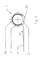
- Figure 1 shows, a printing drum 1 consisting of a support cylinder 2 and a bearing area engraving 3.
- Zone 3 is engraved with the drawing of the imprint that we want to achieve.
- Zone 3 occupies a angle Al less than 360 °.
- Print a mark on a envelope with a transport speed Vt consists of rotate the support cylinder 2, therefore zone 3, so that the tangential peripheral speed of the latter is equal to Vt.
- Angle A2 complementary angle of Al, is not covered by zone 3. It avoids any contact of an envelope 4 with the zone 3 when the envelope 4 leaves the device printing. It is in this angular sector A2 that place the acceleration then deceleration phases of the printing drum.
- FIG. 2 illustrates the state of the art. She shows the evolution of the peripheral speed of the drum 1 during a print cycle.
- the drum is initially at rest.
- An envelope 4 is conveyed by a transport system to the drum 1 at transport speed Vt.
- the system transport has means to identify the position of the casing 4 relative to the drum 1.
- the microprocessor managing the machine triggers when the envelope is in a certain position, at time T1, the rotation of the drum 1.
- T1 and T2 the drum 1 is accelerated so constant so that the peripheral speed linear of drum 1 reaches, in T2, the speed of transport of the envelope Vt.
- the drum 1 has traversed the acceleration angle A3.
- zone 3 affixes its mark on the envelope 4.
- Figure 3 shows the evolution of the speed drum 1 device during a print cycle according to the invention.
- the drum is initially at rest in a position different from that of the figure 2.
- the angle A3 ' made by the front edge of the area printing with the vertical, is much greater than A2 / 2.
- the drum 1 is accelerated so constant so that its linear velocity reaches, in T2, the transport speed of the envelope Vt.
- the drum has traveled the acceleration angle A3 '.
- the printing area 2 puts its mark on the envelope 4.
- the printing being finished in T3 the drum is steadily decelerated so that its linear speed be zero in T4.
- the drum has traversed a deceleration angle A4 '.
Landscapes
- Physics & Mathematics (AREA)
- General Physics & Mathematics (AREA)
- Engineering & Computer Science (AREA)
- Mechanical Engineering (AREA)
- Computer Security & Cryptography (AREA)
- Inking, Control Or Cleaning Of Printing Machines (AREA)
Description
- des moyens d'impression comprenant un tambour d'impression rotatif actionné par un premier moteur, ledit tambour d'impression portant sur une portion de sa surface une partie utile d'impression ;
- des moyens de transport desdits articles, actionnés par un second moteur, amenant lesdits articles en contact avec lesdits moyens d'impression, à une vitesse de transport Vt donnée, et assurant l'évacuation des articles imprimés ;
- des moyens de commande de la vitesse de rotation dudit premier moteur agissant de façon que la vitesse tangentielle dudit tambour d'impression soit maintenue à un plateau égal à ladite vitesse de transport Vt, pendant une phase d'impression correspondant à la durée pendant laquelle un article est en contact avec ladite partie utile d'impression, et soit, en dehors du plateau d'impression, diminuée pendant une phase de décélération qui suit le plateau d'impression, et augmentée jusqu'à la vitesse Vt pendant une phase d'accélération qui précède le plateau suivant,
- la figure 1 est une vue simplifiée de face d'un tambour d'impression,
- la figure 2 présente le profil de vitesse d'un tambour d'impression utilisant la méthode classique de pilotage, le profil étant associé, pour ses points remarquables, à un schéma correspondant du tambour d'impression,
- la figure 3 présente selon les mêmes conventions le profil de vitesse d'un tambour d'impression piloté selon l'invention.
Claims (3)
- Dispositif de pilotage d'une machine d'impression d'articles (4), notamment pour l'affranchissement d'enveloppes (4), du type comportant :caractérisé en ce que lesdits moyens de commande sont agencés pour donner au tambour (1) une vitesse négative après la phase de décélération.des moyens d'impression comprenant un tambour d'impression rotatif (1) actionné par un premier moteur, ledit tambour d'impression (1) portant sur une portion de sa surface une partie utile d'impression (3) ;des moyens de transport desdits articles (4), actionnés par un second moteur, amenant lesdits articles (4) en contact avec lesdits moyens d'impression, à une vitesse de transport Vt donnée, et assurant l'évacuation des articles imprimés (4) ;des moyens de commande de la vitesse de rotation dudit premier moteur agissant de façon que la vitesse tangentielle dudit tambour d'impression (1) soit maintenue à un plateau égal à ladite vitesse de transport Vt, pendant une phase d'impression correspondant à la durée pendant laquelle un article (4) est en contact avec ladite partie utile d'impression (3), et soit, en dehors du plateau d'impression, diminuée pendant une phase de décélération suivant le plateau d'impression, et augmentée jusqu'à la vitesse Vt pendant une phase d'accélération précédant le plateau suivant,
- Dispositif selon la revendication 1, caractérisé en ce que la vitesse est amenée de façon linéaire de Vt à sa vitesse négative minimale, puis ramenée de façon linéaire de celle-ci à Vt.
- Procédé de pilotage d'une machine d'impression à tambour rotatif (1), notamment pour l'affranchissement d'enveloppes (4), du type selon lequel après chaque impression à vitesse de rotation constante dans un sens donné, on décélère la vitesse de rotation du tambour (1), et avant chaque impression suivante, on accélère dans le même sens la vitesse de rotation du tambour, pour atteindre ladite vitesse constante, caractérisé en ce qu'on inverse le sens de rotation du tambour (1) après avoir décéléré la vitesse de rotation après chaque impression.
Applications Claiming Priority (3)
| Application Number | Priority Date | Filing Date | Title |
|---|---|---|---|
| FR9501919A FR2730668B1 (fr) | 1995-02-20 | 1995-02-20 | Dispositif et procede de pilotage d'une machine d'impression notamment de tambour d'affranchisseur |
| FR9501919 | 1995-02-20 | ||
| PCT/FR1996/000187 WO1996026502A1 (fr) | 1995-02-20 | 1996-02-05 | Dispositif et procede de pilotage d'une machine d'impression, notamment de tambour d'affranchisseur |
Publications (2)
| Publication Number | Publication Date |
|---|---|
| EP0811207A1 EP0811207A1 (fr) | 1997-12-10 |
| EP0811207B1 true EP0811207B1 (fr) | 1999-04-28 |
Family
ID=9476309
Family Applications (1)
| Application Number | Title | Priority Date | Filing Date |
|---|---|---|---|
| EP96903050A Expired - Lifetime EP0811207B1 (fr) | 1995-02-20 | 1996-02-05 | Dispositif et procede de pilotage d'une machine d'impression, notamment de tambour d'affranchisseur |
Country Status (6)
| Country | Link |
|---|---|
| US (1) | US5813347A (fr) |
| EP (1) | EP0811207B1 (fr) |
| CA (1) | CA2193509C (fr) |
| DE (1) | DE69602256T2 (fr) |
| FR (1) | FR2730668B1 (fr) |
| WO (1) | WO1996026502A1 (fr) |
Families Citing this family (4)
| Publication number | Priority date | Publication date | Assignee | Title |
|---|---|---|---|---|
| JP2002211031A (ja) * | 2001-01-18 | 2002-07-31 | Fuji Photo Film Co Ltd | 画像記録装置およびその方法 |
| JP2003326820A (ja) * | 2002-05-14 | 2003-11-19 | Toshiba Corp | 紙葉類押印装置 |
| GB0321826D0 (en) * | 2003-09-18 | 2003-10-15 | Graphic Internat Ltd Ab | Improvements in and relating to rotary dies and rotary printing units |
| US20080039913A1 (en) * | 2006-08-09 | 2008-02-14 | Hagay Mizrahi | Aromatherapy blanket pack |
Family Cites Families (12)
| Publication number | Priority date | Publication date | Assignee | Title |
|---|---|---|---|---|
| US3756149A (en) * | 1971-03-15 | 1973-09-04 | Deritend Eng Co | Apparatus for minimizing waste in treating a web |
| US4023489A (en) * | 1976-02-06 | 1977-05-17 | Burroughs Corporation | Document endorsing control circuitry and method for minimizing power consumption requirements |
| US4220084A (en) * | 1978-11-07 | 1980-09-02 | Magnetic Peripherals Inc. | Document endorser apparatus |
| US4232217A (en) * | 1979-04-27 | 1980-11-04 | Burroughs Corporation | Stepper motor drive for a mechanical camshaft |
| US4579054A (en) * | 1982-12-08 | 1986-04-01 | Pitney Bowes Inc. | Stand-alone electronic mailing machine |
| DE177057T1 (de) * | 1984-10-04 | 1989-01-05 | Pitney Bowes, Inc., Stamford, Conn. | Frankiermaschinenvorrichtung mit mikroprozessorgesteuertem gleichstrommotor und verfahren zu dessen gebrauch. |
| US4665353A (en) * | 1984-10-04 | 1987-05-12 | Pitney Bowes Inc. | Microprocessor controlled D.C. motor for controlling tape feeding means |
| US4717136A (en) * | 1984-11-02 | 1988-01-05 | Albert Rutishauser | Process and apparatus for feeding in of recording carriers to the writing roller of an office machine |
| DE3476355D1 (en) * | 1984-11-02 | 1989-03-02 | Albert Rutishauser | Device and process for discontinuously feeding record carriers to the platen of an office machine |
| US5018443A (en) * | 1989-09-15 | 1991-05-28 | Illinois Tool Works Inc. | Position sensor systems for a print head |
| FR2684335B1 (fr) * | 1991-11-29 | 1995-06-16 | Alcatel Satmam | Dispositif de commande pour machine d'impression a la volee, et procede correspondant. |
| CA2085261C (fr) * | 1991-12-19 | 1998-07-14 | Pitney Bowes Inc. | Machine a adresser et a affranchir equipee d'un systeme de commande du tambour d'impression |
-
1995
- 1995-02-20 FR FR9501919A patent/FR2730668B1/fr not_active Expired - Fee Related
-
1996
- 1996-02-05 DE DE69602256T patent/DE69602256T2/de not_active Expired - Fee Related
- 1996-02-05 WO PCT/FR1996/000187 patent/WO1996026502A1/fr not_active Ceased
- 1996-02-05 EP EP96903050A patent/EP0811207B1/fr not_active Expired - Lifetime
- 1996-02-05 US US08/750,892 patent/US5813347A/en not_active Expired - Fee Related
- 1996-02-05 CA CA002193509A patent/CA2193509C/fr not_active Expired - Fee Related
Also Published As
| Publication number | Publication date |
|---|---|
| WO1996026502A1 (fr) | 1996-08-29 |
| FR2730668A1 (fr) | 1996-08-23 |
| US5813347A (en) | 1998-09-29 |
| CA2193509C (fr) | 2004-12-14 |
| DE69602256T2 (de) | 1999-12-02 |
| CA2193509A1 (fr) | 1996-08-29 |
| DE69602256D1 (de) | 1999-06-02 |
| EP0811207A1 (fr) | 1997-12-10 |
| FR2730668B1 (fr) | 1997-05-30 |
Similar Documents
| Publication | Publication Date | Title |
|---|---|---|
| FR2472530A1 (fr) | Appareil de traitement d'une matiere en feuille maintenue sur un support par aspiration | |
| FR2624432A1 (fr) | Imprimeuse | |
| FR2611558A1 (fr) | Dispositif et procede pour affuter les aretes de coupe d'une lame a deplacement alternatif | |
| FR2556280A1 (fr) | Presse d'impression a dispositif de reglage automatique de vitesse | |
| FR2550731A1 (fr) | Machine d'impression en couleurs a reglage de l'espacement des impressions | |
| CA2193509C (fr) | Dispositif et procede de pilotage d'une machine d'impression, notamment de tambour d'affranchisseur | |
| US6311617B1 (en) | Printing press with a vibrator-like inking unit and method of operating the printing press | |
| FR2774082A1 (fr) | Dispositif pour la commande et le reglage d'un aiguillage pour des produits plies | |
| EP0545769B1 (fr) | Dispositif de commande pour machine d'impression à la volée, et procédé correspondant | |
| FR2502129A1 (fr) | Dispositif pour alimenter en feuilles des machines a faconner les feuilles, notamment des machines a doubler | |
| CH434085A (fr) | Dispositif de formage de sachets de conditionnement | |
| FR2464195A1 (fr) | Dispositif pour la depose automatique d'etiquettes autocollantes | |
| FR2655752A1 (fr) | Machine a affranchir a transporteur integre. | |
| FR2729331A1 (fr) | Tete d'impression offset, et machine a imprimer comportant au moins une telle tete d'impression | |
| FR2550995A1 (fr) | Procede et dispositif de reglage assurant l'adaptation aux reperes et la conformite aux longueurs d'impression dans les imprimeuses flexographiques | |
| CN211998222U (zh) | 一种纺织机械用张紧装置 | |
| WO2004012941A2 (fr) | Machine a imprimer. | |
| EP0259210B1 (fr) | Machine de traitement d'objets plats | |
| FR2634034A1 (fr) | Procede et circuit de commande de la vitesse d'un objet pouvant etre mis en mouvement par un mecanisme | |
| EP0604296B1 (fr) | Machine à affranchir électronique à deux tambours d'impression de données fixes et variables | |
| FR2461669A1 (fr) | Appareil de mise en position reperee et presse de surimpression | |
| FR2461968A1 (fr) | Perfectionnements apportes aux dispositifs d'impression a encre magnetique pulverulente | |
| JP3232155B2 (ja) | 搬送コンベアへの物品供給方法及び装置 | |
| EP1163988B1 (fr) | Installation de découpe feuille à feuille avec dispositif de lancement assurant la fonction de calage en position des feuilles | |
| JPH0671588A (ja) | カッター機構 |
Legal Events
| Date | Code | Title | Description |
|---|---|---|---|
| PUAI | Public reference made under article 153(3) epc to a published international application that has entered the european phase |
Free format text: ORIGINAL CODE: 0009012 |
|
| 17P | Request for examination filed |
Effective date: 19961203 |
|
| AK | Designated contracting states |
Kind code of ref document: A1 Designated state(s): CH DE FR GB LI |
|
| GRAG | Despatch of communication of intention to grant |
Free format text: ORIGINAL CODE: EPIDOS AGRA |
|
| 17Q | First examination report despatched |
Effective date: 19980708 |
|
| GRAG | Despatch of communication of intention to grant |
Free format text: ORIGINAL CODE: EPIDOS AGRA |
|
| GRAH | Despatch of communication of intention to grant a patent |
Free format text: ORIGINAL CODE: EPIDOS IGRA |
|
| GRAH | Despatch of communication of intention to grant a patent |
Free format text: ORIGINAL CODE: EPIDOS IGRA |
|
| GRAA | (expected) grant |
Free format text: ORIGINAL CODE: 0009210 |
|
| AK | Designated contracting states |
Kind code of ref document: B1 Designated state(s): CH DE FR GB LI |
|
| REG | Reference to a national code |
Ref country code: CH Ref legal event code: NV Representative=s name: ROTTMANN, ZIMMERMANN + PARTNER AG Ref country code: CH Ref legal event code: EP |
|
| REF | Corresponds to: |
Ref document number: 69602256 Country of ref document: DE Date of ref document: 19990602 |
|
| GBT | Gb: translation of ep patent filed (gb section 77(6)(a)/1977) |
Effective date: 19990812 |
|
| PLBE | No opposition filed within time limit |
Free format text: ORIGINAL CODE: 0009261 |
|
| STAA | Information on the status of an ep patent application or granted ep patent |
Free format text: STATUS: NO OPPOSITION FILED WITHIN TIME LIMIT |
|
| 26N | No opposition filed | ||
| REG | Reference to a national code |
Ref country code: GB Ref legal event code: IF02 |
|
| PGFP | Annual fee paid to national office [announced via postgrant information from national office to epo] |
Ref country code: GB Payment date: 20050202 Year of fee payment: 10 |
|
| PGFP | Annual fee paid to national office [announced via postgrant information from national office to epo] |
Ref country code: FR Payment date: 20050217 Year of fee payment: 10 |
|
| PGFP | Annual fee paid to national office [announced via postgrant information from national office to epo] |
Ref country code: CH Payment date: 20050221 Year of fee payment: 10 |
|
| PGFP | Annual fee paid to national office [announced via postgrant information from national office to epo] |
Ref country code: DE Payment date: 20050331 Year of fee payment: 10 |
|
| REG | Reference to a national code |
Ref country code: CH Ref legal event code: PFA Owner name: SECAP (GROUPE PITNEY BOWES) Free format text: SECAP#21, QUAI ALPHONSE LE GALLO#92100 BOULOGNE BILLANCOURT (FR) -TRANSFER TO- SECAP (GROUPE PITNEY BOWES)#21 QUAI ALPHONSE LE GALLO#92100 BOULOGNE BILLANCOURT (FR) |
|
| REG | Reference to a national code |
Ref country code: FR Ref legal event code: CD |
|
| PG25 | Lapsed in a contracting state [announced via postgrant information from national office to epo] |
Ref country code: GB Free format text: LAPSE BECAUSE OF NON-PAYMENT OF DUE FEES Effective date: 20060205 |
|
| PG25 | Lapsed in a contracting state [announced via postgrant information from national office to epo] |
Ref country code: LI Free format text: LAPSE BECAUSE OF NON-PAYMENT OF DUE FEES Effective date: 20060228 Ref country code: CH Free format text: LAPSE BECAUSE OF NON-PAYMENT OF DUE FEES Effective date: 20060228 |
|
| PG25 | Lapsed in a contracting state [announced via postgrant information from national office to epo] |
Ref country code: DE Free format text: LAPSE BECAUSE OF NON-PAYMENT OF DUE FEES Effective date: 20060901 |
|
| REG | Reference to a national code |
Ref country code: CH Ref legal event code: PL |
|
| GBPC | Gb: european patent ceased through non-payment of renewal fee |
Effective date: 20060205 |
|
| REG | Reference to a national code |
Ref country code: FR Ref legal event code: ST Effective date: 20061031 |
|
| PG25 | Lapsed in a contracting state [announced via postgrant information from national office to epo] |
Ref country code: FR Free format text: LAPSE BECAUSE OF NON-PAYMENT OF DUE FEES Effective date: 20060228 |