EP0811315A2 - Outil à main actionné par moteur - Google Patents
Outil à main actionné par moteur Download PDFInfo
- Publication number
- EP0811315A2 EP0811315A2 EP97108980A EP97108980A EP0811315A2 EP 0811315 A2 EP0811315 A2 EP 0811315A2 EP 97108980 A EP97108980 A EP 97108980A EP 97108980 A EP97108980 A EP 97108980A EP 0811315 A2 EP0811315 A2 EP 0811315A2
- Authority
- EP
- European Patent Office
- Prior art keywords
- handle
- trigger
- trigger element
- section
- tool according
- Prior art date
- Legal status (The legal status is an assumption and is not a legal conclusion. Google has not performed a legal analysis and makes no representation as to the accuracy of the status listed.)
- Withdrawn
Links
- 210000003811 finger Anatomy 0.000 claims description 6
- 210000003813 thumb Anatomy 0.000 claims description 6
- 230000005540 biological transmission Effects 0.000 claims description 3
- 230000001154 acute effect Effects 0.000 description 4
- 230000000694 effects Effects 0.000 description 3
- 230000007704 transition Effects 0.000 description 2
- 238000002485 combustion reaction Methods 0.000 description 1
- 230000006378 damage Effects 0.000 description 1
- 210000004247 hand Anatomy 0.000 description 1
- 230000036544 posture Effects 0.000 description 1
- 230000001681 protective effect Effects 0.000 description 1
Images

Classifications
-
- A—HUMAN NECESSITIES
- A01—AGRICULTURE; FORESTRY; ANIMAL HUSBANDRY; HUNTING; TRAPPING; FISHING
- A01G—HORTICULTURE; CULTIVATION OF VEGETABLES, FLOWERS, RICE, FRUIT, VINES, HOPS OR SEAWEED; FORESTRY; WATERING
- A01G3/00—Cutting implements specially adapted for horticultural purposes; Delimbing standing trees
- A01G3/04—Apparatus for trimming hedges, e.g. hedge shears
- A01G3/047—Apparatus for trimming hedges, e.g. hedge shears portable
- A01G3/053—Apparatus for trimming hedges, e.g. hedge shears portable motor-driven
Definitions
- the invention relates to a motor-operated hand-held device, for example a hedge trimmer, a chainsaw, a jigsaw or the like, in which the tool protrudes elongated or sword-shaped over a side of the housing, such as the front, by an amount that can be greater than the length of the housing.
- the tool works or cuts in a working plane that can be perpendicular to a central plane, for example the longitudinal central plane, of the device and / or parallel to it or in this central plane.
- a drive for example an internal combustion engine, an electric motor or the like, is provided which can drive the elongated, freely projecting tool at the rear end via a gear.
- one or two separate handles are expediently provided, each of which can have a plurality of gripping sections which transversely adjoin one another for relocating the associated hand, in order to position the working plane in any orientation towards the user to bring.
- Inconvenient device postures such as so-called overhead work, in which the device with arms pointing upwards out over the head of the user are ergonomically particularly problematic, especially with regard to the safe holding and guiding the device.
- a single or multiple triggering elements for example push buttons, are provided, which must be actuated and kept actuated to start and to maintain the tool run.
- a release member is released by the user, the tool or drive is immediately stopped because the release member returns to its initial or switch-off position automatically, for example by spring force.
- the release member is expediently arranged so that it can be kept pressed with the hand holding the associated grip, for example with the inside of the fingers encompassing the grip section.
- the invention is also based on the object of providing a hand-held device in which disadvantages of known designs or of the type described are avoided and which can be safely kept in operation, in particular in the case of ergonomically unfavorable use, such as overhead use.
- a trigger element or trigger member is provided as the trigger element, which is located on a trigger side separate from the inside of the handle and can be actuated in particular when gripping the associated handle portion with the thumb or the tip of the thumb of the gripping hand.
- the trigger element is expediently only to be pressed inwards.
- the trigger element is preferably in the region of a handle section which extends approximately in the longitudinal direction of the tool or approximately parallel to the working plane and which is transverse to the working plane or the tool offset and closer to the top of the housing than the tool, which in turn is advantageously located immediately adjacent to the bottom of the housing facing away from it.
- the release element can advantageously be actuated transversely to the longitudinal direction of this grip section in a direction that is transverse to the longitudinal direction of the tool or to the working plane.
- Release elements can be accessible or arranged on the side of the handle, namely on its lateral surfaces that adjoin the inside of the handle and / or on the outside of the handle facing away from the inside, so that the same grip section is equally well gripped with the left or right hand and thereby the release can be actuated.
- the handle also expediently has a trigger element or trigger element on the inside, for example a pistol-like trigger. Both release elements have the same function, so that optionally only one has to be actuated to put the device into operation and hold it.
- the further trigger element is advantageously provided on a further grip section, which lies transversely to the longitudinal directions mentioned, transversely to the working plane and / or behind the first grip section.
- the further grip section can connect at an obtuse angle to the rear end of the first grip section, extend from it towards the working plane or underside of the housing and lie at a distance from the rear side of the housing or the housing wall which limits the receiving space for the drive.
- the actuation directions of the two trigger elements are then transverse to one another, since that of the further trigger element is directed from the inner handle side to the outer handle side facing away from it.
- the second holding or carrying handle is advantageously arranged at a distance in front of the first handle and / or behind the tool or the associated outside of the housing and can have one or more handle sections which are angled to one another and which can all lie transversely to the longitudinal directions mentioned.
- a handle section of the carrying handle is expediently located transversely to the central longitudinal plane of the handle and another handle section approximately parallel to this plane or at an acute angle thereto.
- This grip section can be inclined forward toward its outer end with respect to one of the named longitudinal directions.
- a release member of the type mentioned is expediently provided, namely a release member which operates in the manner described. Only if one of the associated triggering elements is kept pressed with each hand, the running of the tool or the drive is not interrupted. If several trigger elements are provided for each hand, the actuation of a single one is sufficient. In order to be able to work comfortably with every device position, a separate trigger element is provided for each handle section of the carrying handle. Each release element of the respective handle can act on a separate electrical switch that is connected in parallel, while the switches of the two handles are connected in series.
- the release members of the respective handle can also act on a common switch and be connected to it via a transmission member, such as a two-armed swivel lever, a cable or the like.
- a transmission member such as a two-armed swivel lever, a cable or the like.
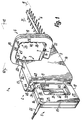
- the device 1 has a head 2, which is essentially formed by a housing 3 and carries a freely projecting tool 4, here a multi-tooth cutting tool with two individual tools which can be reciprocated against one another, one of which has the drive arranged in the housing 3 or motor is coupled so that it is moved in the longitudinal direction of the tool.
- the device 1 has two guide handles, namely a handle 5 and a carrying handle 6.
- the handle 5 forms the rear end of the head 2 and projects as a frame-shaped closed bracket over the rearmost outer side 8 of the housing 3, which projects laterally on both sides over the side surfaces of the handle 5.
- the handle 6 which is also designed as a closed frame or bracket, is arranged at a distance from it, which is closer to the foremost outer side 7 of the housing 3 than the handle 5 and protrudes over both laterally outermost sides 9 of the housing 3.
- Of the Handle 6 can be set back relative to the front 7 or the rear end of the tool 4, which protrudes from the front 7.
- the units 1 to 6 are each formed symmetrically to parallel planes or to a common longitudinal center plane 10, which here is perpendicular to the working plane 11 of the tool 4.
- the central plane of the handle 9 lies in the central plane 10 and the central plane 12 of the handle 6 perpendicular to the plane 10, but inclined forward at an acute angle of less than 45 °.
- the tool 4 and the working plane 11 are closer to the lowermost outside 14 of the units 2, 3, 5, 6 than to their uppermost outside or the top 13 of the housing 3 and can lie directly adjacent to the bottom 14.
- This underside 14 forms the lowermost outside of the device 1 and an essentially flat, right-angled footprint for securely placing the device 1 on a wing.
- the handle 5 forms three separate, mutually angled handle sections 15 to 17, which form its frame legs and can be formed in one piece with the housing 3.
- the housing 3 and the handle 5 expediently consist of two one-piece shell bodies, which are joined in the central plane 10 and accommodate all the structural and functional parts of the drive and the device control between them.
- a shell half of the housing 3 is formed in one piece with a shell half of the handle 5 and forms one of the side surfaces thereof, like the surface 9.
- the elongated device 1 determines a longitudinal direction 50 which is parallel to the longitudinal direction 51 of the tool 4 or to the planes 10 , 11 lies.
- the plane 12 is transverse to the directions 50, 51.
- the handle section 16 closest to the upper side 13 is parallel to the directions 50, 51 and the levels 10, 11 and connects directly to the rear side 8 with its front end.
- the upper end of section 15 is connected at right angles transversely, which is at a distance behind rear side 8 and parallel to it.
- the rear end of section 17 is connected at right angles transversely, the front end of which, like that of section 16, adjoins rear side 8. All sections 15 to 17 lie in a common plane 10 and are each so large that each section can be clutched with one hand.
- the lower outside of section 17 connects continuously to the underside 14 and forms part of the standing area.
- the handle 6 is formed by a separate unit attached to the housing 3 and, like the handle 5, has three sections 18 to 20 which are at an angle to one another, so that it also forms a closed frame or bracket together with the housing 3, which with its frame - or handle sections continuously limited a bracket opening over the circumference.
- the section 18 closest to the upper side 13 and projecting slightly beyond its plane parallel to the underside 14 lies at right angles transversely to the directions 50, 51 or to the plane 10 and parallel to the plane 11, 12 at a short distance from that area of the front side 7 facing him. This area is set back from the area from which the tool 4 protrudes.
- the sections 19, 20 adjoin at an obtuse angle transversely to the ends of the section 18 and extend from the latter downwards in the direction of the tool 4 or the plane 11, wherein they diverge at an acute angle, so that the sections 18 to 20 have a rounded trapezoidal shape form.
- a short leg 21 adjoins at an acute angle transversely inward, with the free end of the handle 6 being fixed rigidly, but non-destructively detachably, to the associated side 9 of the housing 3.
- the handle 6 can also be composed of two shells which are joined in the plane 12 and accommodate the associated control elements between them.
- a supply line or a power cord 22 protrudes from the outside of the handle 5, which is inserted between the switch halves in level 10.
- the handle 5 has a trigger unit 23 and the handle 6 has a trigger unit 24.
- Each unit 23, 24 contains a plurality of separate and separately actuatable release elements which are each to be actuated at right angles transversely to the associated handle section or the associated section side.
- a single release member of each handle 5, 6 must be manually operated and kept operated.
- the handle sections 15 to 17 each extend in the associated longitudinal direction 25 to 27 and the handle sections 18 to 20 each in the associated longitudinal direction 28 to 30.
- the longitudinal directions 26, 27 of the sections 16, 17 lie parallel to the directions 50, 51, while the longitudinal direction 25 of the section 15 is perpendicular to it at right angles and approximately parallel to the longitudinal directions 29, 30 of the sections 19, 20.
- the longitudinal direction 28 of the section 18 is transverse to the directions 25 to 27, 29, 30, 50, 51.
- Each section 15 to 17 forms an innermost handle side 38 adjoining the bow opening, on which, apart from the thumb, the inner sides of all the other fingers of the hand rest when reaching around. This also applies to the innermost handle sides 40 of the sections 18 to 20.
- the inner sides 38 face away from the outermost side 39 of the respectively associated sections 15 to 17 and, like these, lie transversely to the lateral outer surfaces of the handle 5 or the sections 15 facing away from one another to 17.
- a trigger element 31, 33 is arranged as a trigger element, which is to be pressed into this inside for actuation.
- a further trigger element 34 is provided, which is to be pressed into this outside 39 for actuation.
- the element 34 is located directly adjacent to the rear side 8 at the front end of the section 16 in the region of a surface 48 which is recessed in relation to this outer side 39 so that the finger pressure surface of the element 34 can lie in the plane of the outer side 39 or, in contrast, slightly recessed .
- the depression 48 rises to the surface 39 and immediately in front of it the rear side 8 projects upward above the element 34.
- stops 49 for the thumb are formed directly in front of and behind the element 34, so that the element 34 can be easily found with the thumb even when touched only when it is out of the user's field of vision.
- the depression 48 extends over the entire width of the section 5, 16.
- the element 34 is completely sunk into the surface 48.
- the actuation of each of the elements 31, 33, 34 has the same effect, regardless of whether one or more of these trigger elements are actuated.
- the elements 31, 33, 34 act on a common switch.
- release members 35 to 37 which are arranged or accessible on the inner sides 40 of the sections 18 to 20 and are to be pressed into this inner side for actuation.
- the inner sides of the sections 19, 20 face each other and the inner side of the section 18 lies opposite the tool 4, whereby, as in the case of the handle 5, it adjoins the inner sides of the sections 19, 20.
- the links 35 to 37 act on a common switch which is connected in series with the switch of the elements 31, 33, 34, with the motor and the connecting cable 22.
- the actuation directions 41 to 43 of the elements 31 and 33 are in each case from the associated side 38 to the outer side 39 remote therefrom, i.e. outward, directed.
- the actuation direction 44 of the element 34 is from the associated outer side 39 to the inner side 38 facing away from it, i.e. directed inwards or in opposite directions.
- the two elements 33, 34 are to be operated downwards, i.e. in the same direction.
- the direction 44 is transverse or perpendicular.
- the trigger members 35 to 37 can be actuated in the directions 45 to 47, namely from the respective inner side 40 to the outer side of the associated section 18 to 20, ie directed outward parallel to the plane 12.
- the elements 31, 33, 34 and also link 35 is to be operated parallel to level 10.
- the actuation direction 45 is thus transverse or at an angle deviating from 90 ° to the directions 46, 47 of the links 36, 37. All directions 45 to 46 deviate from all directions 41, 43, 44.
- the directions 46, 47 are each at an angle deviating from 90 ° to all directions 41, 43, 44.
- the direction 45 is opposite to the direction 44 and the directions 46, 47 are approximately parallel to the pressure surfaces of the elements 31, 33, 34 as well as the direction 45 transversely to the directions 50, 51 and to the level 10.
- Each trigger element 31, 33, 34 is arranged symmetrically to the level 10 and each trigger element 35 to 37 is arranged symmetrically to the level 12 . Regardless of how the device is to be held for working in relation to the body of the user, this ensures comfortable operation of the units 23, 24 and a secure hold of the device.
- the sections 15, 16 are at an obtuse angle to one another and the correspondingly inclined inside of the section 15 and the element 31 is opposite to an approximately parallel section of the rear side 8.
- the frame opening of the handle 5 is here obtuse-angled, an angle leg being delimited by section 15 and the angle leg directed forwardly by section 16 and a recessed upper side of housing 3. This makes it particularly easy to reach into each opening leg by hand.
- the section 16 is not provided on the inside with a release element, but such an element 31 is only provided on the inside 38 of the section 15.
- the two sections 15, 16 are of approximately the same length and, in contrast, the section 17 is considerably shorter, so that it is not provided here as a handle section.
- the line 22 protrudes from the transition between the sections 15, 17 parallel to the levels 10, 11 and to the direction 50, 51.
- the elements 31, 34 are used to actuate a switch or contact 53 arranged inside the handle 5, 15, the actuating direction of which is directed obliquely backwards and upwards parallel to the direction 41, so that its actuating plunger is carried along by the element 31 in the same direction 41 can.
- the element 34 actuates the switch 53 via a transmission member 54, for example a two-armed pivot lever, one of which Arm in section 16 is movably engaged with element 34 and its other arm is movable in section 15 in engagement with the actuating plunger of switch 53.
- the element 31 acts on the actuating plunger via this arm, since the end of this arm is arranged between the element 31 and the plunger as a pressure body.
- the section 15 is approximately parallel to the handle 6, so that the direction 41 is directed perpendicular to the plane 12 to the rear.
- a protective member 52 is provided behind the tool 4 and above it, which is intended to prevent a hand from falling into the tool 4 when a hand slips off the handle 5 or 6.
- the shield 52 which is parallel to the plane 12, projects above the associated area of the top or front side 7, lies slightly behind that section of the front side 7 from which the tool 4 protrudes and also projects laterally beyond the side surfaces 9.
Landscapes
- Life Sciences & Earth Sciences (AREA)
- Biodiversity & Conservation Biology (AREA)
- Ecology (AREA)
- Forests & Forestry (AREA)
- Environmental Sciences (AREA)
- Harvester Elements (AREA)
Applications Claiming Priority (2)
| Application Number | Priority Date | Filing Date | Title |
|---|---|---|---|
| DE1996122594 DE19622594A1 (de) | 1996-06-05 | 1996-06-05 | Motorisch betriebenes Handgerät |
| DE19622594 | 1996-06-05 |
Publications (2)
| Publication Number | Publication Date |
|---|---|
| EP0811315A2 true EP0811315A2 (fr) | 1997-12-10 |
| EP0811315A3 EP0811315A3 (fr) | 1998-08-26 |
Family
ID=7796236
Family Applications (1)
| Application Number | Title | Priority Date | Filing Date |
|---|---|---|---|
| EP97108980A Withdrawn EP0811315A3 (fr) | 1996-06-05 | 1997-06-04 | Outil à main actionné par moteur |
Country Status (2)
| Country | Link |
|---|---|
| EP (1) | EP0811315A3 (fr) |
| DE (1) | DE19622594A1 (fr) |
Cited By (4)
| Publication number | Priority date | Publication date | Assignee | Title |
|---|---|---|---|---|
| FR2822096A1 (fr) * | 2001-03-16 | 2002-09-20 | Stihl Maschf Andreas | Outil de travail portable, manoeuvre a la main et comportant des appuis de pouce |
| GB2404620A (en) * | 2003-07-14 | 2005-02-09 | Black & Decker Inc | Vegetation pruning device |
| EP1787506A3 (fr) * | 2005-11-21 | 2007-07-11 | Husqvarna UK Limited | Outil motorisé |
| EP2196084A3 (fr) * | 2008-12-11 | 2010-11-10 | Hitachi Koki CO., LTD. | Outil électrique à moteur portable |
Families Citing this family (1)
| Publication number | Priority date | Publication date | Assignee | Title |
|---|---|---|---|---|
| DE19926375A1 (de) | 1999-06-10 | 2000-12-14 | Gardena Kress & Kastner Gmbh | Motorbetriebenes Gartenwerkzeug, insbesondere Heckenschere |
Family Cites Families (15)
| Publication number | Priority date | Publication date | Assignee | Title |
|---|---|---|---|---|
| US3699655A (en) * | 1971-01-18 | 1972-10-24 | Rockwell Mfg Co | Power driven hand tool |
| US4122320A (en) * | 1976-08-16 | 1978-10-24 | Disston, Inc. | Hand-operated double-acting trigger switch |
| DE2651231A1 (de) * | 1976-11-10 | 1978-05-18 | Hugo Freund Fa | Heckenschere mit elektromotorischem antrieb |
| DE2816485C2 (de) * | 1978-04-15 | 1983-09-08 | Reinhold 8531 Hagenbüchach Härtlein | Handgriffausbildung an einem tragbaren kraftbetriebenen Werkzeug, insbesondere Motorsäge, Heckenschere od. dgl. |
| DE3040516A1 (de) * | 1980-10-28 | 1982-05-27 | Fa. Andreas Stihl, 7050 Waiblingen | Sicherheitseinrichtung an einer motorsaege |
| DE3216446A1 (de) * | 1982-05-03 | 1983-11-03 | Fa. Andreas Stihl, 7050 Waiblingen | Sicherheitseinrichtung an einem tragbaren, motorisch angetriebenen handgeraet |
| JPS6039479U (ja) * | 1983-08-26 | 1985-03-19 | 株式会社 共立 | ハンドル |
| DE3610682C2 (de) * | 1986-03-29 | 1994-01-13 | Bosch Gmbh Robert | Griff für Handwerkzeugmaschinen |
| US5150523A (en) * | 1991-07-11 | 1992-09-29 | Ryobi Motor Products Corporation | Deadman switch arrangement for a hedge trimmer |
| IT1252015B (it) * | 1991-11-28 | 1995-05-27 | Black & Decker Inc | Utensile elettrico con sensori di impugnamento |
| US5237752A (en) * | 1992-02-20 | 1993-08-24 | Daryl Maseck | Movable control-handle for chainsaw |
| DE4311624A1 (de) * | 1993-04-08 | 1994-10-13 | Gardena Kress & Kastner Gmbh | Heckenschere |
| DE9308698U1 (de) * | 1993-06-11 | 1994-10-27 | Dolmar GmbH, 22045 Hamburg | Handarbeitsgerät mit einem Antrieb |
| DE4332986C2 (de) * | 1993-09-28 | 1999-03-11 | Fraunhofer Ges Forschung | Handgriff für motorgetriebene Arbeitsgeräte mit verstellbarem Bedienelement |
| GB9323459D0 (en) * | 1993-11-13 | 1994-01-05 | Black & Decker Inc | Improved power tool guard |
-
1996
- 1996-06-05 DE DE1996122594 patent/DE19622594A1/de not_active Withdrawn
-
1997
- 1997-06-04 EP EP97108980A patent/EP0811315A3/fr not_active Withdrawn
Cited By (6)
| Publication number | Priority date | Publication date | Assignee | Title |
|---|---|---|---|---|
| FR2822096A1 (fr) * | 2001-03-16 | 2002-09-20 | Stihl Maschf Andreas | Outil de travail portable, manoeuvre a la main et comportant des appuis de pouce |
| US7168132B2 (en) | 2001-03-16 | 2007-01-30 | Andreas Stihl Ag & Co. | Portable handheld work apparatus having thumb supports |
| GB2404620A (en) * | 2003-07-14 | 2005-02-09 | Black & Decker Inc | Vegetation pruning device |
| EP1787506A3 (fr) * | 2005-11-21 | 2007-07-11 | Husqvarna UK Limited | Outil motorisé |
| EP2196084A3 (fr) * | 2008-12-11 | 2010-11-10 | Hitachi Koki CO., LTD. | Outil électrique à moteur portable |
| US8813733B2 (en) | 2008-12-11 | 2014-08-26 | Hitachi Koki Co., Ltd. | Hand-held engine-powered tool |
Also Published As
| Publication number | Publication date |
|---|---|
| EP0811315A3 (fr) | 1998-08-26 |
| DE19622594A1 (de) | 1997-12-11 |
Similar Documents
| Publication | Publication Date | Title |
|---|---|---|
| DE69900518T2 (de) | Ausverriegelung für Schalter | |
| DE69937377T2 (de) | Sperrmechanismus für kraftbetriebenes Werkzeug | |
| EP2040868B2 (fr) | Machine-outil portative, en particulier scie manuelle | |
| DE3531059A1 (de) | Motorisch betriebenes handgeraet | |
| EP3792008A1 (fr) | Appareil de travail portatif doté d'un outil | |
| EP3760025B1 (fr) | Dispositif de commande à poignée et appareil de travail entraîné par un moteur | |
| EP0834248B1 (fr) | Taille-haie motorisé | |
| DE19905086A1 (de) | Batteriegetriebenes, handgeführtes Elektrowerkzeug | |
| DE102010007193B4 (de) | Tragbare TopHandle-Arbeitsmaschine | |
| DE19800176B4 (de) | Steuerelement für ein tragbares motorangetriebenes Werkzeug | |
| EP3892082B1 (fr) | Poignée pour un appareil de travail guidé à la main et débroussailleuse | |
| DE602004002630T2 (de) | Schwenkbare Griffanordnung für ein Kraftwerkzeug | |
| EP2308651B1 (fr) | Machine-outil manuelle dotée d'un crochet | |
| DE602004002438T2 (de) | Abriegelungsmechanismus für eine schwenkbare Griffanordnung eines Kraftwerkzeugs | |
| EP0622015B1 (fr) | Cisaille à haies | |
| DE602004000897T2 (de) | Betätigungsmechanismus für ein Kraftwerkzeug | |
| EP4059666B1 (fr) | Appareil de travail guidé à la main | |
| EP0811315A2 (fr) | Outil à main actionné par moteur | |
| DE602004001941T2 (de) | Griffanordnung für ein Kraftwerkzeug | |
| EP1059025A2 (fr) | Outil de jardin motorisé, notamment taille-haie | |
| EP0611634B1 (fr) | Couteau à usages multiples | |
| DE602004002348T2 (de) | Griffanordnung für ein Kraftwerkzeug | |
| DE102011006931A1 (de) | Griff für Kabelumwicklung | |
| EP1782682A2 (fr) | Appareil de travail guidé manuellement | |
| DE2319219B2 (de) | Elektromotorisch angetriebene Grasschere |
Legal Events
| Date | Code | Title | Description |
|---|---|---|---|
| PUAI | Public reference made under article 153(3) epc to a published international application that has entered the european phase |
Free format text: ORIGINAL CODE: 0009012 |
|
| AK | Designated contracting states |
Kind code of ref document: A2 Designated state(s): AT CH DE FR GB IT LI NL SE |
|
| PUAL | Search report despatched |
Free format text: ORIGINAL CODE: 0009013 |
|
| AK | Designated contracting states |
Kind code of ref document: A3 Designated state(s): AT BE CH DE DK ES FI FR GB GR IE IT LI LU MC NL PT SE |
|
| 17P | Request for examination filed |
Effective date: 19981009 |
|
| AKX | Designation fees paid |
Free format text: AT CH DE FR GB IT LI NL SE |
|
| RBV | Designated contracting states (corrected) |
Designated state(s): AT CH DE FR GB IT LI NL SE |
|
| 17Q | First examination report despatched |
Effective date: 20010523 |
|
| GRAP | Despatch of communication of intention to grant a patent |
Free format text: ORIGINAL CODE: EPIDOSNIGR1 |
|
| STAA | Information on the status of an ep patent application or granted ep patent |
Free format text: STATUS: THE APPLICATION IS DEEMED TO BE WITHDRAWN |
|
| 18D | Application deemed to be withdrawn |
Effective date: 20040331 |