EP0811419A2 - Katalytische Vorrichtung zur Reinigung von Abgasen aus Dieselmotoren - Google Patents
Katalytische Vorrichtung zur Reinigung von Abgasen aus Dieselmotoren Download PDFInfo
- Publication number
- EP0811419A2 EP0811419A2 EP97109233A EP97109233A EP0811419A2 EP 0811419 A2 EP0811419 A2 EP 0811419A2 EP 97109233 A EP97109233 A EP 97109233A EP 97109233 A EP97109233 A EP 97109233A EP 0811419 A2 EP0811419 A2 EP 0811419A2
- Authority
- EP
- European Patent Office
- Prior art keywords
- catalyst
- catalytic apparatus
- sio
- exhaust gas
- zro
- Prior art date
- Legal status (The legal status is an assumption and is not a legal conclusion. Google has not performed a legal analysis and makes no representation as to the accuracy of the status listed.)
- Withdrawn
Links
Images


Classifications
-
- B—PERFORMING OPERATIONS; TRANSPORTING
- B01—PHYSICAL OR CHEMICAL PROCESSES OR APPARATUS IN GENERAL
- B01D—SEPARATION
- B01D53/00—Separation of gases or vapours; Recovering vapours of volatile solvents from gases; Chemical or biological purification of waste gases, e.g. engine exhaust gases, smoke, fumes, flue gases, aerosols
- B01D53/34—Chemical or biological purification of waste gases
- B01D53/92—Chemical or biological purification of waste gases of engine exhaust gases
- B01D53/94—Chemical or biological purification of waste gases of engine exhaust gases by catalytic processes
- B01D53/944—Simultaneously removing carbon monoxide, hydrocarbons or carbon making use of oxidation catalysts
-
- B—PERFORMING OPERATIONS; TRANSPORTING
- B01—PHYSICAL OR CHEMICAL PROCESSES OR APPARATUS IN GENERAL
- B01J—CHEMICAL OR PHYSICAL PROCESSES, e.g. CATALYSIS OR COLLOID CHEMISTRY; THEIR RELEVANT APPARATUS
- B01J35/00—Catalysts, in general, characterised by their form or physical properties
- B01J35/19—Catalysts containing parts with different compositions
-
- B—PERFORMING OPERATIONS; TRANSPORTING
- B01—PHYSICAL OR CHEMICAL PROCESSES OR APPARATUS IN GENERAL
- B01D—SEPARATION
- B01D2257/00—Components to be removed
- B01D2257/30—Sulfur compounds
- B01D2257/302—Sulfur oxides
Definitions
- the present invention relates to a catalytic apparatus for purifying an exhaust gas emitted from a diesel engine. It is possible for the catalytic apparatus not only to oxidize and purify hydrocarbons (hereinafter abbreviated to as "HC”) and soluble organic fractions (hereinafter abbreviated to as "SOF”) included in an exhaust gas emitted from a diesel engine, but also to minimize an emission of diesel particulates.
- HC hydrocarbons
- SOF soluble organic fractions
- the conventional trapping type apparatus captures the diesel particulates included in exhaust gases emitted from diesel engines in order to inhibit them from being emitted, and is especially effective to the exhaust gases of high dry-soot content.
- the conventional trapping type apparatus requires a recycling apparatus for burning the captured diesel particulates. Accordingly, in view of actual application, there still remain the following problems associated with the conventional trapping type apparatus: namely; its DPE (i.e., diesel particulates filter) is cracked during the recycling operation; its DPE is clogged by ashes; and the conventional trapping type apparatus itself complicates an exhaust system inevitably.
- one of the open type SOF cracking catalysts is disclosed in Japanese Unexamined Patent Publication (KOKAI) No. 3-38,255, for example.
- a catalyst is utilized which comprises a catalyst carrier layer formed of activated alumina, etc., and a platinum-group catalyst ingredient, etc., loaded on the catalyst carrier layer.
- the open type SOF cracking catalyst oxidizes and decomposes SOF together with CO and HC, thereby purifying an exhaust gas emitted from a diesel engine.
- This open type SOF cracking catalyst has a disadvantage in that it removes the dry soot with a low removing rate.
- the open type SOF cracking catalyst can efficiently decompose SOF at elevated temperatures ,it suffers from a disadvantage in that its catalyst ingredient exhibits a poor catalytic activity at low temperatures to show deteriorated SOF purifying performance.
- SOF are not decomposed but turned into soot. Consequently, there arises a phenomenon that the resulting soot deposits in the honeycomb-shaped cellular passages of the catalyst support of the open type SOF cracking catalyst.
- the open type SOF cracking catalyst is clogged by the deposited soot to suffer from deteriorated catalytic performance.
- hydrocarbons such as light oil, and the like
- hydrocarbons are added to exhaust gases in order to reduce and purify NO x included in the exhaust gases.
- the reduction reaction of NO x is relatively less likely to take place in exhaust gases emitted from diesel engines, because oxygen is included in a greater amount in the exhaust gases. Accordingly, the emusion of SOF may be increased occasionally, because the hydrocarbons, which have not taken part in the reduction reaction of NO x , are emitted as they are.
- the open type SOF cracking catalyst suffers from another problem in that the emission of particulates may be enlarged: namely; SO 2 is oxidized to produce SO 3 or SO 4 in a high-temperature range, and the resulting SO 3 or SO 4 is turned into sulfates to increase the emission of particulates.
- SO 2 is not measured as particulates, but SO 3 or SO 4 is measured as particulates.
- gaseous oxygen exists in a sufficient amount so that the oxidation of SO 2 is likely to take place.
- the applicant of the present invention proposed a novel catalyst for purifying an exhaust gas emitted from a diesel engine in Japanese Unexamined Patent Publication (KOKAI) No. 6-198,181.
- the catalyst includes Pt which is loaded on an upstream side in an exhaust gas flow, and Pd which is loaded on a downstream side in the exhaust gas flow.
- the novel catalyst it is difficult for the novel catalyst to completely oxide and purify SOF when the temperature of the exhaust gas is low, for example, when a diesel engine is started or when it is operated idly. Accordingly, excessive SOF are adsorbed on a catalyst support formed of alumina, etc., on the upstream side. Then, the adsorbed SOF are eliminated from the catalyst support to flow to the downstream side when the temperature of the exhaust gas is elevated to a high temperature. Since Pd is of lower oxidizing activity, SOF are subjected to incomplete combustion. Thus, SOF are emitted in an incompletely oxidized state, and released in air as white fumes.
- novel catalyst when the novel catalyst is installed to an upstream-side of an exhaust system which is adjacent to a diesel engine, an exhaust gas of elevated temperature is flowed into the novel catalyst. Accordingly, Pt oxidizes SO 2 to generate the sulfates.
- novel catalyst when the novel catalyst is installed to a downstream-side of an exhaust system which is away from a diesel engine, it is difficult for the novel catalyst to purify SOF.
- the novel catalyst disclosed in the publication suffers from a drawback in that it offers a narrow temperature range where both of the SOF purification and the sulfate-generation control can be carried out satisfactorily.
- catalytic apparatus for purifying an exhaust gas emitted from a diesel engine, catalytic apparatus which can exhibit good performance in both of the SOF purification and the sulfate-generation control is a wide temperature range.
- a catalytic apparatus for purifying an exhaust gas emitted from a diesel engine can carry out the aforementioned object, and comprises:
- the exhaust gas emitted from a diesel engine is first flowed into the first catalyst.
- SOF included in the exhaust gas is turned into low-molecular-weight substances by cracking, and is then flowed to a downstream side.
- the temperature of the exhaust gas introduced into the first catalyst can be relatively high, because the first catalyst is disposed on an upstream side in an exhaust system of the diesel engine. Consequently, the temperature of the exhaust gas is likely to reach the cracking temperature of SOF.
- the first catalyst is less likely to oxidize SO 2 . Accordingly, even when the temperature of the exhaust gas is high, SO 2 included in the exhaust gas is little oxidized, and it is flowed to a downstream side as it is.
- the second catalyst oxidizes the low-molecular-weight substances, which have been cracked by the first catalyst, and purifies them by turning them into H 2 O and CO 2 .
- SOF are likely to be oxidized and purified, because they have been turned into low-molecular-weight substances. Consequently, SOF are purified with high conversion.
- the temperature of the exhaust gas introduced into the second catalyst can be low, because the second catalyst is disposed on a downstream side in the exhaust system of the diesel engine. For instance, when the exhaust system of the diesel engine is prolonged by 1 m, the temperature of the exhaust gas is dropped by 100 °C approximately. Accordingly, even when the second catalyst is of high oxidizing activity, SO 2 is less likely to be oxidized. As a result, the sulfates can be inhibited from generating.
- the present catalytic apparatus can offer a wide temperature range where both of the SOF purification and the sulfate-generation control can be carried out satisfactorily.
- the present catalytic apparatus can exhibit extraordinary performance in both of the SOF purification and the sulfate-generation control in a wide temperature range by appropriately designing the disposition of the first and second catalysts. Therefore, the present catalytic apparatus can satisfactorily purify the exhaust gases emitted from diesel engines in the wide temperature range.
- the first catalyst can be one which is capable of cracking SOF included in a exhaust gas emitted from a diesel engine, and which is less likely to oxidize SO 2 .
- the first catalyst can include a catalyst support which is formed of the following components: SiO 2 , a mixture of SiO 2 and Al 2 O 3 , a composite oxide of SiO 2 and Al 2 O 3 , a mixture of SiO 2 and MgO, a composite oxide of SiO 2 and MgO, a zeolite having a cracking capability, Fe 2 O 3 , Fe 3 O 4 , CeO 2 , a mixture of CeO 2 and ZrO 2 , a composite oxide CeO 2 and ZrO 2 , a SO 4 -ZrO 2 super strong acid, a WO 3 -ZrO 2 super strong acid, a WO 3 -SnO 2 super strong acid, a WO 3 -TiO 2 super strong acid, a WO 3 -Fe
- the zeolite having a cracking capability can be a type Y zeolite, for example, USY (ultra stabilized Y-type zeolite (Trade Mark of TOSO Corp.)) 200 produced by TOSO Corp.
- these components can be employed independently to constitute the catalyst support, or combinations of two or more of the components can be employed to constitute the catalyst support.
- the first catalyst can be constituted by the catalyst support alone, or it can be constituted by further loading a catalyst ingredient on the catalyst support.
- the first catalyst can employ one or more of the following catalyst ingredients: Pt, Rh, and Pd.
- Pd is preferred especially, because it is of low oxidizing activity. It is further preferable to load Pd in an amount of from 0.01 to 5 grams, furthermore preferable from 0.1 to 2.0 grams, with respect to 1 liter of the catalyst support.
- the oxidizing activity of Pt or Rh can be kept low so that SO 2 can be inhibited from oxidizing.
- the loading amount of Pt or Rh falls preferably in a range of from 0.01 to 5 grams, furthermore preferable from 0.1 to 2.0 grams, with respect to 1 liter of the catalyst support.
- the second catalyst can be oxidizing catalysts which have been used conventionally.
- a catalyst support of the second catalyst can be exemplified by the following components: SiO 2 , Al 2 O 3 , TiO 2 , ZrO 2 , CeO 2 , Fe 2 O 3 , and Fe 3 O 4 . Note these components can be employed independently to constitute the catalyst support, or combinations of two or more of the components can be employed to constitute the catalyst support.
- the following catalyst ingredients can be loaded on the catalyst support: Pt, Rh, and Pd.
- Pt is preferred especially, because it is of high oxidizing activity. It is further preferable to load Pt in an amount of from 0.01 to 5 grams, furthermore preferable from 0.1 to 2.0 grams, with respect to 1 liter of the catalyst support.
- the second catalyst employs a catalyst ingredient whose oxidizing activity is higher than that of the catalyst ingredient loaded on the first catalyst.
- the catalyst ingredient on the second catalyst in an amount greater that of the catalyst ingredient loaded on the first catalyst, thereby adjusting the oxidizing activity of the second catalyst higher than that of the first catalyst.
- the first catalyst can preferably be positioned adjacent to a diesel engine as close as possible, for example, immediately below an exhaust manifold of a diesel engine.
- the second catalyst can preferably be positioned away from a diesel engine as far as possible, but is disposed within an area where the temperature of the exhaust gas is held in such a range that permits the catalyst ingredient loaded on the second catalyst to exhibit the oxidizing activity.
- the present catalytic apparatus can be applied to an exhaust system in which hydrocarbons, such as light oil, and the like, are added to an exhaust gas.
- NO x is reduced simultaneously by the first catalyst with the cracking of SOF.
- SOF which have been turned into low-molecular-weight substances, are likely to react with residual NO x . Consequently, not only NO x can be purified with improved performance, but also SOF can be purified with enhanced conversion.
- a honeycomb-shaped support substrate was prepared.
- the support substrate had a volume of 1.7 L, and was formed of cordierite.
- a coating layer was formed on the support substrate in an amount of 100 g with respect to 1 L of the support substrate, thereby making a honeycomb-shaped catalyst support.
- the coating layer included an alumina powder in an amount of 10% by weight, and a silica powder in an amount of 90% by weight.
- the resulting honeycomb-shaped catalyst support with the coating layer formed thereon was immersed into an aqueous solution of palladium nitrate having a predetermined concentration of palladium nitrate. Thereafter, the honeycomb-shaped catalyst was taken out of the aqueous solution, and was blown off to remove excessive water.
- honeycomb-shaped catalyst support was calcinated to load Pd on the coating layer, thereby completing a first catalyst.
- Pd was loaded on the honeycomb-shaped catalyst support in an amount of 0.025 grams with respect to 1 L of the honeycomb-shaped catalyst support.
- honeycomb-shaped support substrate was prepared.
- the support substrate had a volume of 1.7 L, and was formed of cordierite.
- a coating layer was formed on the support substrate in an amount of 100g with respect to 1 L of the support substrate, thereby making a honeycomb-shaped catalyst support.
- the coating layer included a silica powder in a amount of 100% by weight
- the resulting honeycomb-shaped catalyst support with the coating layer formed thereon was immersed into an aqueous solution of dinitrodiammine platinum nitrate having a predetermined concentration of dinitrodiammine platinum nitrate. Thereafter, the honeycomb-shaped catalyst was taken out of the aqueous solution, and was blown off to remove excessive water.
- honeycomb-shaped catalyst support was calcinated to load Pt on the coating layer, thereby completing a second catalyst.
- Pt was loaded on the honeycomb-shaped catalyst support in an amount of 1.0 gram with respect to 1 L of the honeycomb-shaped catalyst support.
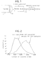
- the resultant first catalyst was disposed immediately below an exhaust manifold 10 of a diesel engine 1, and the resultant second catalyst was disposed on a downstream side away from the first catalyst by 1,200 mm in an exhaust system.
- the diesel engine 1 had a displacement of 2.6 L.
- the diesel engine 1 was operated at 2,000 rpm under a load of 70 Nm. Note that this operating condition of the diesel engine 1 is referred to as a new EC (European Community) mode. Under the operating condition, an exhaust gas introduced into the first catalyst, and an exhaust gas emitted therefrom were analyzed with a gas chromatograph in order to determine the compositions of SOF included in the exhaust gases. The results of the analysis are illustrated in Fig. 2 as a molecular-weight-distribution diagram. For substances having a specific number of carbon atoms, the contents of the substances included in SOF were calculated so as to illustrate the molecular-weight-distribution diagram.
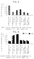
- FIG. 3 illustrates the results of the examination as a ratio with respect to the concentration of PM included in the exhaust gas at the outlet of a comparative catalytic apparatus of Comparative Example No. 1 described later.
- Fig. 4 illustrates the results of the examination as ratios with respect to the concentrations of HC and CO, which were included in the exhaust gas at the outlet of a comparative catalytic apparatus of Comparative Example No. 3 described later. Note that, in Figs. 3 and 4, the concentrations are expressed by arbitrary units (A. U.).
- a honeycomb-shaped support substrate was prepared.
- the support substrate had a volume of 1.7 L, and was formed of cordierite.
- a coating layer was formed on the support substrate in an amount of 100 g with respect to 1 L of the support substrate, thereby making a honeycomb-shaped catalyst support.
- the resulting honeycomb-shaped catalyst support with the coating layer armed thereon was immersed into an aqueous solution of dinitrodiammine platinum nitrate having a predetermined concentration of dinitrodiammine platinum nitrate. Thereafter, the honeycomb-shaped catalyst was taken out of the aqueous solution, and was blown off to remove excessive water. Finally, the honeycomb-shaped catalyst support was calcinated to load Pt on the coating layer, thereby completing a first catalyst. Pt was loaded on the honeycomb-shaped catalyst support in an amount of 0.1 gram with respect to 1 L of the honeycomb-shaped catalyst support.
- honeycomb-shaped support substrate was prepared.
- the support substrate had a volume of 1.7 L, and was formed of cordierite.
- a coating layer was formed on the support substrate in an amount of 100 g with respect to 1 L of the support substrate, thereby making a honeycomb-shaped catalyst support.
- the coating layer included a titania powder in an amount of 100% by weight.
- the resulting honeycomb-shaped catalyst support with the coating layer formed thereon was immersed into an aqueous solution of dinitrodiammine platinum nitrate having a predetermined concentration of dinitrodiammine platinum nitrate. Thereafter, the honeycomb-shaped catalyst was taken out of the aqueous solution, and was blown off to remove excessive water.
- honeycomb-shaped catalyst support was calcinated to load Pt on the coating layer, thereby completing a second catalyst.
- Pt was loaded on the honeycomb-shaped catalyst support in an amount of 1.5 grams with respect to 1 L of the honeycomb-shaped catalyst support.
- Figs. 3 and 4 illustrate the results of the examination.
- a comparative catalytic apparatus (i.e., Comparative Example No. 1) was prepared in the same manner as the First Preferred Embodiment, but with the following exceptions: namely; a single catalyst was prepared by loading Pt thereon in an amount of 1.5 grams in the same manner as the second catalyst of the First Preferred Embodiment; the resulting single catalyst was disposed at the position where the first catalyst of the First Preferred Embodiment was disposed, and no catalyst was disposed on a downstream side with respect to the thus disposed single catalyst.
- a comparative catalytic apparatus (i.e., Comparative Example No. 2) was prepared in the same manner as the First Preferred Embodiment, but with the following exceptions: namely; only the first catalyst of the First Preferred Embodiment was disposed on the upstream side; and the second catalyst thereof was not disposed.
- a comparative catalytic apparatus (i.e., Comparative Example No. 3) was prepared in the same manner as the First Preferred Embodiment, but with the following exception: namely; the first catalyst and second catalyst of the First Preferred Embodiment were not used. Hence, the exhaust gas emitted from the diesel engine 1 was emitted to the outside as it is.
- a comparative catalytic apparatus (i.e., Comparative Example No. 4) was prepared in the same manner as the First Preferred Embodiment, but with the following exceptions: namely; the first catalyst of the First Preferred Embodiment was disposed on the downstream side; and the second catalyst thereof was disposed on the upstream side.
- a first catalyst and a second catalyst were disposed at reversed positions with respect to those of the First Preferred Embodiment.
- the resulting comparative catalytic apparatus of Comparative Example No. 4 was examined for the concentrations of PM, HC and CO in the same manner as the First Preferred Embodiment.
- Figs. 3 and 4 illustrate the results of the examination.
- Comparative Example No. 2 it is appreciated from Fig. 3 that the exhaust gas purified by Comparative Example No. 2 contained PM in a less concentration than the exhaust gas emitted from Comparative Example No. 3. Hence, it was apparent that the sulfates were inhibited from generating by only employing the first catalyst of the First Preferred Embodiment in which Pd was loaded on the SiO 2 -Al 2 O 3 catalyst support. However, it is understood from Fig. 4 that Comparative Example No. 2 could reduce HC and CO, included in the exhaust gas, by a trivial amount with respect to the concentration of HC and CO, included in the exhaust gas emitted from Comparative Example No. 3. This phenomena imply that SO 2 can be kept from oxidizing by utilising the second catalyst of the First Preferred Embodiment alone, but HC and CO cannot be readily oxidized and purified thereby.
- the catalytic apparatus of the Second Preferred Embodiment exhibited good purifying performance similarly to that of the First Preferred Embodiment.
- the catalytic apparatus of the Second Preferred Embodiment employed the following arrangements: namely: Pt was loaded on both of the first and second catalysts, but was loaded on the second catalyst in a greater amount than on the first catalyst in order to enhance the oxidizing activity of the second catalyst; and the first catalyst utilized the catalyst support formed of zeolite which not only exhibited a good adsorbing ability to SOF but also had cracking performance. It is understood that, due to these arrangements, the catalytic apparatus of the Second Preferred Embodiment could purify all of SOF, HC and CO efficiently, and could simultaneously inhibit the sulfates from generating.
- Comparative Example No. 4 included the first catalyst and the second catalyst which were arranged completely reversely with respect to those of the First Preferred Embodiment. Therefore, Comparative Example No. 4 produced the sulfates in a large amount, and purified HC and CO insufficiently.
- n-C 16 H 34 (n-hexedecane) was flowed through their first catalysts only in an amount of 40 mg at 150 °C in a diesel exhaust-gas atmosphere.
- the diesel exhaust-gas atmosphere herein means that the atmosphere included O 2 in an amount of 10% by volume, and the balance of N 2 .
- the resulting substances whose number of carbon atoms was 10 or more were removed by cold trapping, and the residual gaseous compounds were collected with a gas pack.
- the components of the gaseous compounds collected in the gas pack were analyzed with a gas chromatograph. Figs.
- FIG. 5 and 7 show a gas chromatogram on the components which had a number of carbon atoms from 2 to 5, and which were included in the exhaust gas emitted from the first catalyst of the Second Preferred Embodiment and Comparative Example No. 1, respectively.
- Figs. 6 and 8 show a gas chromatogram on the components which had a number of carbon atoms from 6 to 10, and which were included in the exhaust gas emitted from the first catalyst of the Second Preferred Embodiment and Comparative Example No. 1, respectively.
- n-C 16 H 34 was little cracked by the first catalyst of the comparative catalytic apparatus of Comparative Example No. 1.
- n-C 16 H 34 was cracked by the first catalyst of the catalytic apparatus of the Second Preferred Embodiment to low-molecular-weight compounds, such as C 2 H 4 , C 2 H 6 , C 3 H 8 , C 3 H 6 , n-C 6 H 14 , toluene, xylene, etc.
- a catalytic apparatus for purifying an exhaust gas emitted from a diesel engine includes a first catalyst, and a second catalyst.
- the first catalyst is disposed on an upstream side in an exhaust system of a diesel engine, has a predetermined oxidizing activity, can crack SOF (i.e., soluble organic fractions) contained in an exhaust gas emitted from the diesel engine, and is less likely to oxidize SO 2 .
- the second catalyst is disposed on a downstream side with respect to the first catalyst in the exhaust system, has an oxidizing activity higher than that of the first catalyst, and can oxidize and purify the SOF cracked to low-molecular-weight substances by the first catalyst. The SOF are cracked by the first catalyst so that they are likely to be oxidized.
- the SOF can be oxidized and purified by the second catalyst. Whilst, SO 2 is not oxidized by the first catalyst. Consequently, SO 2 is less likely to be oxidized by the second catalyst, because the temperature of the exhaust gas is decreased. Therefore, sulfates can be inhibited from generating.
Landscapes
- Chemical & Material Sciences (AREA)
- Engineering & Computer Science (AREA)
- Chemical Kinetics & Catalysis (AREA)
- Health & Medical Sciences (AREA)
- Biomedical Technology (AREA)
- Environmental & Geological Engineering (AREA)
- Analytical Chemistry (AREA)
- General Chemical & Material Sciences (AREA)
- Oil, Petroleum & Natural Gas (AREA)
- Combustion & Propulsion (AREA)
- Materials Engineering (AREA)
- Organic Chemistry (AREA)
- Exhaust Gas After Treatment (AREA)
- Exhaust Gas Treatment By Means Of Catalyst (AREA)
- Catalysts (AREA)
Applications Claiming Priority (4)
| Application Number | Priority Date | Filing Date | Title |
|---|---|---|---|
| JP14567296 | 1996-06-07 | ||
| JP145672/96 | 1996-06-07 | ||
| JP9126933A JPH1052628A (ja) | 1996-06-07 | 1997-05-16 | ディーゼルエンジンの排ガス浄化用触媒装置 |
| JP126933/97 | 1997-05-16 |
Publications (2)
| Publication Number | Publication Date |
|---|---|
| EP0811419A2 true EP0811419A2 (de) | 1997-12-10 |
| EP0811419A3 EP0811419A3 (de) | 1998-07-01 |
Family
ID=26463009
Family Applications (1)
| Application Number | Title | Priority Date | Filing Date |
|---|---|---|---|
| EP97109233A Withdrawn EP0811419A3 (de) | 1996-06-07 | 1997-06-06 | Katalytische Vorrichtung zur Reinigung von Abgasen aus Dieselmotoren |
Country Status (2)
| Country | Link |
|---|---|
| EP (1) | EP0811419A3 (de) |
| JP (1) | JPH1052628A (de) |
Cited By (3)
| Publication number | Priority date | Publication date | Assignee | Title |
|---|---|---|---|---|
| EP1063010A4 (de) * | 1998-03-09 | 2002-09-18 | Osaka Gas Co Ltd | Katalysator zur entfernung von kohlenwasserstoffen aus abgasen und verfahren zur reinigung von abgasen |
| WO2007093325A1 (de) * | 2006-02-15 | 2007-08-23 | Hte Aktiengesellschaft The High Throughput Experimentation Company | Oxidationskatalysator zur abgasbehandlung und verfahren zu seiner herstellung |
| EP1832332A1 (de) | 2006-03-09 | 2007-09-12 | Haldor Topsoe A/S | Verfahren zur Reinigung von schwefelhaltigem Abgas |
Families Citing this family (6)
| Publication number | Priority date | Publication date | Assignee | Title |
|---|---|---|---|---|
| JP4352486B2 (ja) * | 1998-11-17 | 2009-10-28 | 東ソー株式会社 | 排ガス浄化触媒及び排ガス浄化方法 |
| JP2002339728A (ja) * | 2001-05-16 | 2002-11-27 | Hino Motors Ltd | 排気浄化装置 |
| KR100908979B1 (ko) | 2002-11-08 | 2009-07-22 | 에미텍 게젤샤프트 퓌어 에미시온스테크놀로기 엠베하 | 배기장치 및 배기장치의 작동방법 |
| KR100681076B1 (ko) * | 2005-11-22 | 2007-02-08 | 기아자동차주식회사 | 차량용 글로브 박스 |
| JP5277891B2 (ja) * | 2008-11-17 | 2013-08-28 | 三菱自動車工業株式会社 | 排気浄化装置 |
| JP5698002B2 (ja) * | 2011-01-12 | 2015-04-08 | 日野自動車株式会社 | 排気浄化装置 |
Family Cites Families (3)
| Publication number | Priority date | Publication date | Assignee | Title |
|---|---|---|---|---|
| DE4008371A1 (de) * | 1989-03-15 | 1990-09-20 | Riken Kk | Abgasreiniger und verfahren zum reinigen von abgasen |
| ATE171258T1 (de) * | 1990-11-26 | 1998-10-15 | Catalytica Inc | Mehrstufenverfahren für die verbrennung von brennstoffmischungen |
| EP0622107B1 (de) * | 1993-04-28 | 2000-02-09 | Toyota Jidosha Kabushiki Kaisha | Katalysator zur Reinigung von Abgasen aus Dieselmotoren |
-
1997
- 1997-05-16 JP JP9126933A patent/JPH1052628A/ja active Pending
- 1997-06-06 EP EP97109233A patent/EP0811419A3/de not_active Withdrawn
Cited By (8)
| Publication number | Priority date | Publication date | Assignee | Title |
|---|---|---|---|---|
| EP1063010A4 (de) * | 1998-03-09 | 2002-09-18 | Osaka Gas Co Ltd | Katalysator zur entfernung von kohlenwasserstoffen aus abgasen und verfahren zur reinigung von abgasen |
| US6602481B1 (en) | 1998-03-09 | 2003-08-05 | Osaka Gas Company Limited | Catalyst for removing hydrocarbons from exhaust gas and method for clarification of exhaust gas |
| US6887446B2 (en) | 1998-03-09 | 2005-05-03 | Osaka Gas Company Limited | Catalyst for removing hydrocarbons from exhaust gas and method for purification of exhaust gas |
| US7371706B2 (en) | 1998-03-09 | 2008-05-13 | Osaka Gas Company Limited | Catalyst for removing hydrocarbons from exhaust gas and method for purification of exhaust gas |
| WO2007093325A1 (de) * | 2006-02-15 | 2007-08-23 | Hte Aktiengesellschaft The High Throughput Experimentation Company | Oxidationskatalysator zur abgasbehandlung und verfahren zu seiner herstellung |
| EP1832332A1 (de) | 2006-03-09 | 2007-09-12 | Haldor Topsoe A/S | Verfahren zur Reinigung von schwefelhaltigem Abgas |
| US7569197B2 (en) | 2006-03-09 | 2009-08-04 | Haldor Topsoe A/S | Process for purification of sulphur-containing exhaust gas |
| CN101073746B (zh) * | 2006-03-09 | 2012-08-29 | 赫多特普索化工设备公司 | 净化含硫废气的方法 |
Also Published As
| Publication number | Publication date |
|---|---|
| EP0811419A3 (de) | 1998-07-01 |
| JPH1052628A (ja) | 1998-02-24 |
Similar Documents
| Publication | Publication Date | Title |
|---|---|---|
| US5958828A (en) | Catalyst for purifying exhaust gas | |
| KR100484688B1 (ko) | 엔진배기가스처리장치및사용방법 | |
| US5780002A (en) | Exhaust gas cleaner and method for cleaning exhaust gas | |
| JP6683680B2 (ja) | 窒素酸化物還元用触媒 | |
| US5714130A (en) | Exhaust gas cleaner and method for cleaning exhaust gas | |
| JP5854995B2 (ja) | ガソリンエンジン排ガス処理システム | |
| US6066587A (en) | Catalyst for purifying exhaust gas | |
| EP1319433B1 (de) | Reinigungskatalysator für Verbrennungsmotorabgas und Reinigungsverfahren | |
| KR100370486B1 (ko) | 내연기관의 배기가스 정화장치, 배기가스정화방법 및배기가스정화촉매 | |
| CN103437864B (zh) | 压燃式发动机废气净化方法及装置 | |
| US20080282683A1 (en) | Device for the purification of exhaust gas | |
| EP1660217A1 (de) | Katalysatoranordnung und verfahren zur abgasentgiftung von unter mageren bedingungen betriebenen verbrennungsmotoren | |
| EP0622107B1 (de) | Katalysator zur Reinigung von Abgasen aus Dieselmotoren | |
| EP0719580A1 (de) | Vorrichtung und Verfahren zur Reinigung von Abgas | |
| EP0562516B1 (de) | Verfahren zur Reinigung von Abgasen | |
| KR20180111903A (ko) | 망간을 함유하는 다층 질소 산화물 저장 촉매 | |
| EP0661089A2 (de) | Vorrichtung und Verfahren zur Reinigung von Abgas | |
| US6767526B1 (en) | Method for treating by combustion carbon-containing particles in an internal combustion engine exhaust circuit | |
| KR20150120460A (ko) | 질소 산화물의 감소를 위한 방법 및 촉매 | |
| KR20050072140A (ko) | 배기가스 정화용 촉매 및 배기가스 정화 방법 | |
| US5972828A (en) | Method of manufacturing catalyst for cleaning exhaust gas released from internal combustion engine, and catalyst for the same | |
| US20080064587A1 (en) | Oxidation Catalyst for Exhaust Gas Purification, Catalyst Structure for Exhaust Gas Purification and Method for Purifying Exhaust Gas | |
| EP0815925A1 (de) | Vorrichtung zur Reinigung der Abgases eines Dieselmotors | |
| JPH07829A (ja) | 希薄混合気燃焼エンジン用卑金属触媒系 | |
| JPH1052628A (ja) | ディーゼルエンジンの排ガス浄化用触媒装置 |
Legal Events
| Date | Code | Title | Description |
|---|---|---|---|
| PUAI | Public reference made under article 153(3) epc to a published international application that has entered the european phase |
Free format text: ORIGINAL CODE: 0009012 |
|
| 17P | Request for examination filed |
Effective date: 19970704 |
|
| AK | Designated contracting states |
Kind code of ref document: A2 Designated state(s): DE FR GB |
|
| PUAL | Search report despatched |
Free format text: ORIGINAL CODE: 0009013 |
|
| AK | Designated contracting states |
Kind code of ref document: A3 Designated state(s): AT BE CH DE DK ES FI FR GB GR IE IT LI LU MC NL PT SE |
|
| AKX | Designation fees paid |
Free format text: DE FR GB |
|
| RBV | Designated contracting states (corrected) |
Designated state(s): DE FR GB |
|
| STAA | Information on the status of an ep patent application or granted ep patent |
Free format text: STATUS: THE APPLICATION IS DEEMED TO BE WITHDRAWN |
|
| 18D | Application deemed to be withdrawn |
Effective date: 19991231 |