EP0811439A2 - Dispositif pour la perforation des tÔles - Google Patents
Dispositif pour la perforation des tÔles Download PDFInfo
- Publication number
- EP0811439A2 EP0811439A2 EP97108834A EP97108834A EP0811439A2 EP 0811439 A2 EP0811439 A2 EP 0811439A2 EP 97108834 A EP97108834 A EP 97108834A EP 97108834 A EP97108834 A EP 97108834A EP 0811439 A2 EP0811439 A2 EP 0811439A2
- Authority
- EP
- European Patent Office
- Prior art keywords
- control
- plunger
- control slide
- sheet
- punches
- Prior art date
- Legal status (The legal status is an assumption and is not a legal conclusion. Google has not performed a legal analysis and makes no representation as to the accuracy of the status listed.)
- Granted
Links
Images


Classifications
-
- B—PERFORMING OPERATIONS; TRANSPORTING
- B21—MECHANICAL METAL-WORKING WITHOUT ESSENTIALLY REMOVING MATERIAL; PUNCHING METAL
- B21D—WORKING OR PROCESSING OF SHEET METAL OR METAL TUBES, RODS OR PROFILES WITHOUT ESSENTIALLY REMOVING MATERIAL; PUNCHING METAL
- B21D28/00—Shaping by press-cutting; Perforating
- B21D28/24—Perforating, i.e. punching holes
- B21D28/246—Selection of punches
-
- B—PERFORMING OPERATIONS; TRANSPORTING
- B21—MECHANICAL METAL-WORKING WITHOUT ESSENTIALLY REMOVING MATERIAL; PUNCHING METAL
- B21D—WORKING OR PROCESSING OF SHEET METAL OR METAL TUBES, RODS OR PROFILES WITHOUT ESSENTIALLY REMOVING MATERIAL; PUNCHING METAL
- B21D28/00—Shaping by press-cutting; Perforating
- B21D28/24—Perforating, i.e. punching holes
- B21D28/26—Perforating, i.e. punching holes in sheets or flat parts
Definitions
- the invention relates to a device for perforating metal sheets with the features according to the preamble of claim 1.
- Perforated sheets are used extensively in numerous industries, namely as screens and filters in the food industry, in mining and in gravel pits, as protective covers for phono devices, construction and machine tools, as partitions and decorations, as components in household appliances, in office furniture, in Aircraft and in industrial construction.
- perforating wide presses for sheet metal with continuous or periodically interrupted hole patterns made from strip or sheet material in Series production, and strip presses to produce single sheets, larger sheet formats and thicknesses with individual hole patterns.
- the sheet metal plates While in a strip press the sheet metal plates can be moved relative to the perforating tool with a clamping table in two mutually perpendicular coordinates, in the case of a perforating wide press feed rollers, the sheet metal plates or strips convey between an upper tool, usually a plurality of punches, and a lower tool. a die, step by step in synchronism with the work cycle of the press in a feed direction.
- the punches of the perforating wide press are arranged in rows across the feed direction. They are kept in a stamp holder.
- a plunger of the press pushes it through a stamp guide plate and presses it through the sheet into corresponding holes in the die.
- a scraper prevents the sheet from sticking to the stamp when it is withdrawn. It is rigid or is shifted out of phase with the plunger.
- the invention has for its object to produce common hole patterns in series with simple means, which can have an increasing and / or decreasing hole-free area in the feed direction, e.g. Circles, triangles, trapezoids etc.
- a control slide from one side transversely to the feed direction are gradually pushed into the power flow, so that one or more punches are additionally activated after each feed. This creates triangular or trapezoidal hole patterns. If the control spool is shorter than the associated row of punches and if it is gradually moved back and forth, serpentine hole patterns can be created.
- stamps can still be activated separately, even if they are only a small one Have a distance from each other, since the control spool can be adjusted in any small steps.
- An electrical or hydraulic stepper motor which drives the spool via pinions, toothed belts and a toothed rack which is attached to the control slide, expediently serves this purpose.
- the stepper motor is mounted directly on the plunger, so that it follows the movement of the plunger and no relative movement between the plunger and the stepper motor has to be taken into account.
- it is advantageous to attach it to the press body and to compensate for the resulting relative movement during the ram stroke by means of a sliding sleeve that works telescopically with a drive spindle.
- More lace patterns e.g. B. circles, ellipses, parabolas, etc. can be made with several spools that can be adjusted together or separately depending on the pattern. They are expediently offset from one another in the feed direction and arranged to overlap. Furthermore, one or more rows of stamps of the same or different lengths can be assigned to each control slide. The end parts of the control slide can be designed so that only one stamp of a row of stamps is activated when moving.
- stamps of different lengths are used and the control slide consists of several superimposed strips that can be adjusted against each other in different positions.
- Each position is given a total thickness in the stroke direction, which is matched to the punch lengths so that only the punches that are long enough to penetrate the sheet at the given total thickness are active.
- a perforating wide press generally contains the following essential assemblies, namely a perforating device 1, a feed device 2, a separating and notching device 3, a separating shear 4 and corresponding drive devices (not shown in more detail).
- the assemblies are mounted in a press body 5.
- the feed device 2 comprises two pairs of feed rollers 6, which are each mounted in front of and behind the perforating device 1 in the press body 5 and between which a sheet 39 is gradually conveyed by the perforating wide press in time with the press stroke.
- the feed direction 7 and the stroke direction 16 are marked with arrows.
- the perforating device 1 includes a press table 8 on which a die 9 is fastened by means of clamping devices 10.
- a perforated plate 11 forms the upper part of the die 9, over which the sheet 39 is guided.
- the perforated plate 11 and the die 9 have holes 12 and bores 13 into which punches 15 engage during the perforation process by punching out corresponding sheet metal disks from the sheet 39.
- the stamps 15 are held longitudinally displaceably in a stamp holding plate 18.
- the punch guide plate 17 guides the punch 15 in the longitudinal direction and at the same time ensures that the plate 39 does not get stuck during the upward stroke. It can be rigid or, as shown, can be moved out of phase with the plunger movement by a separate wiper drive 19.
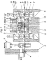
- the stamp holding plate 18 is attached to a plunger 14. This is driven by an eccentric drive, not shown, and carries out a stroke movement in cycles.
- a free space 22 is provided in the plunger 14 above the plunger 15, into which the plunger 15 can retreat, provided that they are not activated by a control device.
- control device consists of one or more control slides 20, which are displaced transversely to the feed direction 7 into the free space 22 and fill the space between the stamps 15 to be activated and the plunger 14. So that the power flow between the plunger 14 and the plunger 15 is established so that they can penetrate through the plate 39.
- the control valve (s) 20 are guided in a slide guide 21 attached to the tappet 14.
- a stepper / servo motor 38 drives them via a sliding sleeve 37, a drive spindle 36, pinions 35, 33, 31, 27, toothed belts 34 and 30 and via a hollow shaft 32, shaft 28 and rack 26.
- the stepper / servo motor 38 and the sliding sleeve 37 are on Press body 5 mounted, while the other drive parts are attached to the plunger 14 and participate in the lifting movement with this.
- the relative movement between the ram 14 and the press body 5 compensates for the sliding sleeve 37, which works telescopically with the drive spindle 36.
- control slides 20 can be adjusted jointly by one drive; expediently, however, they are driven independently of one another by a plurality of drives.
- the variant according to FIG. 4 shows, in addition to the control slides 20, control strips 23, 24, which lie one above the other at latching steps 25.
- the control strips 23, 24 can be displaced relative to one another and thereby assume different latching positions in which they have a different overall thickness 40 in the stroke direction 16. Different gaps can thus be realized between the stamps 15 and the control slides 20 or the control strips 23, 24.
- more complex perforated patterns can be produced, e.g. B. can be controlled in the locking step shown with the greatest overall thickness 40 of the control slide 20, the shortest stamp 15, while the longer stamp 15 are always activated regardless of the position of the control slide 20. If the control strips 23, 24 are moved into a position with a lower overall thickness 40, the shorter punches 15 remain independent of the position of the Control slide 20 inactive, while the longer stamp 15 are activated by the control slide 20.
- the control slide 20 of FIG. 5 are arranged offset to each other in the feed direction 7 and overlap by a certain amount.
- the stamps 15 are also arranged in staggered rows.
- a control slide 20 can activate the punches 15 on one side of the sheet, while the other control slide 20 activates the punches 15 on the other side of the sheet.
- the number of stamps 15 assigned to the respective control slides 20 can be the same or different and can be divided symmetrically or asymmetrically.
- a series of stamps 15 can also be assigned to a control slide 20.
- an end edge 41 e.g. B. bevels
- one or more punches 15 of one row can be activated in front of the punches 15 of another row in the direction of adjustment of the control slide 20.
Landscapes
- Engineering & Computer Science (AREA)
- Mechanical Engineering (AREA)
- Perforating, Stamping-Out Or Severing By Means Other Than Cutting (AREA)
Applications Claiming Priority (2)
| Application Number | Priority Date | Filing Date | Title |
|---|---|---|---|
| DE19622843A DE19622843A1 (de) | 1996-06-07 | 1996-06-07 | Vorrichtung zum Perforieren von Blechen |
| DE19622843 | 1996-06-07 |
Publications (3)
| Publication Number | Publication Date |
|---|---|
| EP0811439A2 true EP0811439A2 (fr) | 1997-12-10 |
| EP0811439A3 EP0811439A3 (fr) | 1998-03-18 |
| EP0811439B1 EP0811439B1 (fr) | 2000-08-16 |
Family
ID=7796368
Family Applications (1)
| Application Number | Title | Priority Date | Filing Date |
|---|---|---|---|
| EP97108834A Expired - Lifetime EP0811439B1 (fr) | 1996-06-07 | 1997-06-03 | Dispositif pour la perforation des tôles |
Country Status (3)
| Country | Link |
|---|---|
| EP (1) | EP0811439B1 (fr) |
| DE (2) | DE19622843A1 (fr) |
| ES (1) | ES2150171T3 (fr) |
Cited By (3)
| Publication number | Priority date | Publication date | Assignee | Title |
|---|---|---|---|---|
| EP0963802A3 (fr) * | 1998-06-10 | 2001-04-18 | Schuler Pressen GmbH & Co. KG | Presse à perforer avec système d'entrainement d'un poinçon unique |
| EP1234922A1 (fr) * | 2001-02-19 | 2002-08-28 | Mäder AG Innenausbau | Procédé et dispositif pour la fabrication d'un élément insonorisant plat |
| CN107855405A (zh) * | 2017-12-26 | 2018-03-30 | 海泉风雷新能源发电股份有限公司 | 一种钢带冲孔装置 |
Families Citing this family (1)
| Publication number | Priority date | Publication date | Assignee | Title |
|---|---|---|---|---|
| BE1030004B1 (nl) * | 2021-12-10 | 2023-07-10 | Soenen Tech Nv | Perforatiepers met vier schuiven en werkwijze voor het aansturen van een perforatiepers met vier schuiven |
Family Cites Families (2)
| Publication number | Priority date | Publication date | Assignee | Title |
|---|---|---|---|---|
| BE848845A (nl) * | 1976-11-29 | 1977-03-16 | Ponsgereedschap, | |
| AT405145B (de) * | 1993-12-17 | 1999-05-25 | Felsner Franz | Anordnung und verfahren zur spanlosen bearbeitung von material oder werkstücken |
-
1996
- 1996-06-07 DE DE19622843A patent/DE19622843A1/de not_active Withdrawn
-
1997
- 1997-06-03 ES ES97108834T patent/ES2150171T3/es not_active Expired - Lifetime
- 1997-06-03 EP EP97108834A patent/EP0811439B1/fr not_active Expired - Lifetime
- 1997-06-03 DE DE59702182T patent/DE59702182D1/de not_active Expired - Lifetime
Cited By (3)
| Publication number | Priority date | Publication date | Assignee | Title |
|---|---|---|---|---|
| EP0963802A3 (fr) * | 1998-06-10 | 2001-04-18 | Schuler Pressen GmbH & Co. KG | Presse à perforer avec système d'entrainement d'un poinçon unique |
| EP1234922A1 (fr) * | 2001-02-19 | 2002-08-28 | Mäder AG Innenausbau | Procédé et dispositif pour la fabrication d'un élément insonorisant plat |
| CN107855405A (zh) * | 2017-12-26 | 2018-03-30 | 海泉风雷新能源发电股份有限公司 | 一种钢带冲孔装置 |
Also Published As
| Publication number | Publication date |
|---|---|
| ES2150171T3 (es) | 2000-11-16 |
| EP0811439B1 (fr) | 2000-08-16 |
| DE59702182D1 (de) | 2000-09-21 |
| EP0811439A3 (fr) | 1998-03-18 |
| DE19622843A1 (de) | 1997-12-11 |
Similar Documents
| Publication | Publication Date | Title |
|---|---|---|
| DE4128194C2 (de) | Vorrichtung zum automatischen Herstellen von Blechteilen | |
| EP2806986B1 (fr) | Procédé et dispositif destinés à relier deux extrémités de bandes métalliques | |
| EP0278046A1 (fr) | Outil pour l'estampage de figures de matrice complexes à partir d'un ruban métallique | |
| DE3228378C2 (de) | Transferlinie für die taktweise Bearbeitung von Werkstücken | |
| DE3311593C1 (de) | Verfahren zum Herausschneiden oder -trennen von Teilen aus einer Werkstuecktafel auf einer Schneidpresse sowie Schneidpresse zur Durchfuehrung des Verfahrens | |
| DE4112882C2 (fr) | ||
| EP0215385A1 (fr) | Procédé et dispositif pour assembler des plaques par des ergots poinçonnés | |
| DE3339503A1 (de) | Stanzmaschine und werkzeugsatz fuer stanzmaschinen | |
| DE2829681C2 (de) | Vorrichtung zum kontinuierlichen Stanzen von Löchern in stabförmige Hohlkörper | |
| EP0811438B1 (fr) | Dispositif de coupe et d'encochage pour des tôles perforées | |
| DE3149621A1 (de) | Stanzvorrichtung | |
| EP0811439B1 (fr) | Dispositif pour la perforation des tôles | |
| DE2704246C2 (de) | Pressenkopf mit mehreren Stempeln und Abstreifern | |
| DE3841683A1 (de) | Vorrichtung zum ausschneiden und ggf. gleichzeitigen formen von teilen aus blechtafeln | |
| DE1937818A1 (de) | Verfahren und Vorrichtung zum Ausstanzen sechseckiger Rohlinge | |
| DE2502866C2 (de) | Vorrichtung und Verfahren zum Schneiden eines noch plastischen Porenbetonblockes | |
| DE3204032C2 (fr) | ||
| DE2852909A1 (de) | Vorrichtung zum verbinden wenigstens zweier bauteile durch ein schnitt-umform- verfahren | |
| DE3336660C1 (de) | Vorrichtung zum Herstellen von Löchern in flächenhaftem Material | |
| DD145011A3 (de) | Einrichtung zum entstapeln magneti ierbarer bleche | |
| DE1527922B2 (de) | Zufuehreinrichtung an einem stanz- und biegeautomaten | |
| DE2631818B2 (de) | Zigarrenperforiereinrichtung | |
| DE2802972A1 (de) | Stanz- und knabbermaschine | |
| DE19620597C2 (de) | Vorrichtung zur Bearbeitung von Lagenmaterial | |
| DD283781A5 (de) | Vorschubeinrichtung zum zufuehren von blechtafeln zu einem stanzwerkzeug |
Legal Events
| Date | Code | Title | Description |
|---|---|---|---|
| PUAI | Public reference made under article 153(3) epc to a published international application that has entered the european phase |
Free format text: ORIGINAL CODE: 0009012 |
|
| AK | Designated contracting states |
Kind code of ref document: A2 Designated state(s): BE CH DE ES FR GB IT LI SE |
|
| PUAL | Search report despatched |
Free format text: ORIGINAL CODE: 0009013 |
|
| AK | Designated contracting states |
Kind code of ref document: A3 Designated state(s): BE CH DE ES FR GB IT LI SE |
|
| 17P | Request for examination filed |
Effective date: 19980817 |
|
| AKX | Designation fees paid |
Free format text: BE CH DE ES FR GB IT LI SE |
|
| RBV | Designated contracting states (corrected) |
Designated state(s): BE CH DE ES FR GB IT LI SE |
|
| 17Q | First examination report despatched |
Effective date: 19981125 |
|
| RAP1 | Party data changed (applicant data changed or rights of an application transferred) |
Owner name: SCHULER PRESSEN GMBH & CO. KG |
|
| GRAG | Despatch of communication of intention to grant |
Free format text: ORIGINAL CODE: EPIDOS AGRA |
|
| 17Q | First examination report despatched |
Effective date: 19981125 |
|
| GRAG | Despatch of communication of intention to grant |
Free format text: ORIGINAL CODE: EPIDOS AGRA |
|
| GRAH | Despatch of communication of intention to grant a patent |
Free format text: ORIGINAL CODE: EPIDOS IGRA |
|
| GRAH | Despatch of communication of intention to grant a patent |
Free format text: ORIGINAL CODE: EPIDOS IGRA |
|
| GRAA | (expected) grant |
Free format text: ORIGINAL CODE: 0009210 |
|
| AK | Designated contracting states |
Kind code of ref document: B1 Designated state(s): BE CH DE ES FR GB IT LI SE |
|
| REG | Reference to a national code |
Ref country code: CH Ref legal event code: EP |
|
| REF | Corresponds to: |
Ref document number: 59702182 Country of ref document: DE Date of ref document: 20000921 |
|
| REG | Reference to a national code |
Ref country code: CH Ref legal event code: NV Representative=s name: CABINET ROLAND NITHARDT CONSEILS EN PROPRIETE INDU |
|
| ITF | It: translation for a ep patent filed | ||
| REG | Reference to a national code |
Ref country code: ES Ref legal event code: FG2A Ref document number: 2150171 Country of ref document: ES Kind code of ref document: T3 |
|
| ET | Fr: translation filed | ||
| GBT | Gb: translation of ep patent filed (gb section 77(6)(a)/1977) |
Effective date: 20001106 |
|
| PLBE | No opposition filed within time limit |
Free format text: ORIGINAL CODE: 0009261 |
|
| STAA | Information on the status of an ep patent application or granted ep patent |
Free format text: STATUS: NO OPPOSITION FILED WITHIN TIME LIMIT |
|
| 26N | No opposition filed | ||
| REG | Reference to a national code |
Ref country code: GB Ref legal event code: IF02 |
|
| PGFP | Annual fee paid to national office [announced via postgrant information from national office to epo] |
Ref country code: GB Payment date: 20020527 Year of fee payment: 6 |
|
| PGFP | Annual fee paid to national office [announced via postgrant information from national office to epo] |
Ref country code: FR Payment date: 20020622 Year of fee payment: 6 |
|
| PGFP | Annual fee paid to national office [announced via postgrant information from national office to epo] |
Ref country code: CH Payment date: 20020625 Year of fee payment: 6 |
|
| PGFP | Annual fee paid to national office [announced via postgrant information from national office to epo] |
Ref country code: SE Payment date: 20020626 Year of fee payment: 6 Ref country code: ES Payment date: 20020626 Year of fee payment: 6 Ref country code: BE Payment date: 20020626 Year of fee payment: 6 |
|
| PG25 | Lapsed in a contracting state [announced via postgrant information from national office to epo] |
Ref country code: GB Free format text: LAPSE BECAUSE OF NON-PAYMENT OF DUE FEES Effective date: 20030603 |
|
| PG25 | Lapsed in a contracting state [announced via postgrant information from national office to epo] |
Ref country code: SE Free format text: LAPSE BECAUSE OF NON-PAYMENT OF DUE FEES Effective date: 20030604 Ref country code: ES Free format text: LAPSE BECAUSE OF NON-PAYMENT OF DUE FEES Effective date: 20030604 |
|
| PG25 | Lapsed in a contracting state [announced via postgrant information from national office to epo] |
Ref country code: LI Free format text: LAPSE BECAUSE OF NON-PAYMENT OF DUE FEES Effective date: 20030630 Ref country code: CH Free format text: LAPSE BECAUSE OF NON-PAYMENT OF DUE FEES Effective date: 20030630 Ref country code: BE Free format text: LAPSE BECAUSE OF NON-PAYMENT OF DUE FEES Effective date: 20030630 |
|
| BERE | Be: lapsed |
Owner name: *SCHULER PRESSEN G.M.B.H. & CO. K.G. Effective date: 20030630 |
|
| GBPC | Gb: european patent ceased through non-payment of renewal fee |
Effective date: 20030603 |
|
| EUG | Se: european patent has lapsed | ||
| REG | Reference to a national code |
Ref country code: CH Ref legal event code: PL |
|
| PG25 | Lapsed in a contracting state [announced via postgrant information from national office to epo] |
Ref country code: FR Free format text: LAPSE BECAUSE OF NON-PAYMENT OF DUE FEES Effective date: 20040227 |
|
| REG | Reference to a national code |
Ref country code: FR Ref legal event code: ST |
|
| REG | Reference to a national code |
Ref country code: ES Ref legal event code: FD2A Effective date: 20030604 |
|
| PG25 | Lapsed in a contracting state [announced via postgrant information from national office to epo] |
Ref country code: IT Free format text: LAPSE BECAUSE OF NON-PAYMENT OF DUE FEES;WARNING: LAPSES OF ITALIAN PATENTS WITH EFFECTIVE DATE BEFORE 2007 MAY HAVE OCCURRED AT ANY TIME BEFORE 2007. THE CORRECT EFFECTIVE DATE MAY BE DIFFERENT FROM THE ONE RECORDED. Effective date: 20050603 |
|
| PGFP | Annual fee paid to national office [announced via postgrant information from national office to epo] |
Ref country code: DE Payment date: 20110616 Year of fee payment: 15 |
|
| REG | Reference to a national code |
Ref country code: DE Ref legal event code: R119 Ref document number: 59702182 Country of ref document: DE Effective date: 20130101 |
|
| PG25 | Lapsed in a contracting state [announced via postgrant information from national office to epo] |
Ref country code: DE Free format text: LAPSE BECAUSE OF NON-PAYMENT OF DUE FEES Effective date: 20130101 |