EP0811443A1 - Tête de roulage tangentiel - Google Patents
Tête de roulage tangentiel Download PDFInfo
- Publication number
- EP0811443A1 EP0811443A1 EP97107896A EP97107896A EP0811443A1 EP 0811443 A1 EP0811443 A1 EP 0811443A1 EP 97107896 A EP97107896 A EP 97107896A EP 97107896 A EP97107896 A EP 97107896A EP 0811443 A1 EP0811443 A1 EP 0811443A1
- Authority
- EP
- European Patent Office
- Prior art keywords
- thread
- rolling head
- roller
- rollers
- holder
- Prior art date
- Legal status (The legal status is an assumption and is not a legal conclusion. Google has not performed a legal analysis and makes no representation as to the accuracy of the status listed.)
- Granted
Links
Images


Classifications
-
- B—PERFORMING OPERATIONS; TRANSPORTING
- B21—MECHANICAL METAL-WORKING WITHOUT ESSENTIALLY REMOVING MATERIAL; PUNCHING METAL
- B21H—MAKING PARTICULAR METAL OBJECTS BY ROLLING, e.g. SCREWS, WHEELS, RINGS, BARRELS, BALLS
- B21H3/00—Making helical bodies or bodies having parts of helical shape
- B21H3/02—Making helical bodies or bodies having parts of helical shape external screw-threads ; Making dies for thread rolling
- B21H3/04—Making by means of profiled-rolls or die rolls
- B21H3/042—Thread-rolling heads
- B21H3/048—Thread-rolling heads working tangentially
Definitions
- the invention relates to a tangential rolling head according to the preamble of claim 1.
- Tangential roller heads in which thread rollers are rotatably mounted on two fork-shaped roller head arms for producing a thread, are generally known.
- the thread rolling head with the non-driven thread rollers is moved from the side onto the rotating workpiece, so that the rotational movement of the workpiece is transmitted to the thread rollers.
- the pitch of the thread to be produced results from the pitch of the thread the thread rolling.
- the thread rolls must be in a certain position to each other at the beginning of a thread rolling process and also during thread rolling. Otherwise there is no guarantee that the threads of one thread roller will engage in the threads generated on the workpiece by the other thread roller.
- the holes of the thread roller and pinion must be aligned with each other so that the axis can be inserted. This assembly requires some skill and is with one some effort. Since two installable rotational positions are possible for the rotating position of the thread roller, the fitter must ensure that the thread roller is installed in the correct rotational position.
- the invention has for its object to provide a tangential thread rolling head, in which the installation of the thread rolls is facilitated and the risk of installation in the wrong rotational position is avoided.
- the interacting claws of the thread roller and pinion designed so that the roller can only be inserted laterally in a single defined rotational position.
- this is achieved, for example, in that the ends of a pair of opposing claws on the thread roller each lie on the leg of an acute angle, the claws of the pinion being complementary in such a way that the angle formed by them diverges outwards .
- Such a design of the thread roller and pinion makes it possible, when the pinion is already installed, for the thread roller to be inserted laterally into the arm of the rolling head only in a single rotational position. Any other position would block the insertion.
- the claws are shaped at the ends with an angle so that the axes of the pinion and thread roller coincide when the claws are fully inserted laterally.
- the conical design of the ends of the claws of the pinion and thread roller not only ensure the rotational position, but also the end position. After the thread roller has been fully inserted, an alignment of the holes of the thread roller and pinion is guaranteed at the same time, so that the axis can be passed straight through without any problems.
- the roller head arms are pivotally mounted on the roller head holder about a common axis.
- an adjustment mechanism is provided to adjust the distance between the thread rolling axes according to the diameter of the thread to be formed. From the publications mentioned, for example G 81 26 319, it is known to arrange an adjusting screw in the arm of the two-armed lever of the rolling head arm facing the holder, the mutually facing ends of the adjusting screws being located opposite one another. The thread pitch can be changed by turning the two set screws. Once the change has been finally made, and to measure the distance it is known to insert a gauge between the thread rolls, the distance taken is fixed with the help of another locking screw.
- Such an adjustment mechanism has several disadvantages. One is that operation must be carried out from two different sides.
- a further embodiment of the invention provides that a single adjusting screw in one roll head arm interacts with a fixed jaw of the other roll head arm to adjust the distance between the thread rolls.
- the single screw can be arranged to save space so that the overall length of the thread rolling head can be significantly reduced compared to conventional designs.
- a further embodiment of the invention provides that the adjusting screw is arranged approximately at the level of the common axis of the roller head arms, namely obliquely to a central plane which extends between the roller head arms through the common axis of the roller head arms.
- the jaw connected to the other roller head arm extends beyond the center plane in the direction of the set screw. A particularly short rolling head is obtained in this way.
- an embodiment of the invention provides that measuring points, preferably measuring balls, are arranged on the outside of the rolling head arms for determining the center distance of the thread rolls.
- measuring points preferably measuring balls
- conventional tangential roller heads there is a separate teaching for each thread used. This increases the effort for the operator.
- a single conventional measuring instrument can be used, for example a micrometer screw or the like, in order to precisely determine the center distance of the thread rolls.
- a specific setting gauge can be omitted.
- an embodiment of the invention provides that at least one roller head arm is designed as a double-armed lever and on the arm assigned to the holder an attachment is provided which interacts with an adjustment mechanism for adjusting the attachment on the holder.
- the approach can cooperate with a nut which sits on a threaded spindle and which is guided in a rotationally fixed manner.
- the storage of the threaded spindle in the holder leads to a linear adjustment of the nut on the threaded spindle when the threaded spindle rotates and thus to a pivoting of the associated rolling head arm.
- the rolling head arms are, as is known per se, biased against one another by at least one spring, the pivoting of the one rolling head arm leads to the other arm also being pivoted. This allows the rolling head to be aligned with the center plane.
- the spindle is preferably accessible from both ends, so that the operator can choose the end that is more favorable in each case in order to achieve the center setting.
- the adjustment mechanism is mounted symmetrically on the holder.
- the rolling head can be installed rotated by 180 ° on the holder without the adjustment mechanism having to be converted.
- a scale is attached to an arm of the two-armed lever for the roller head arm, which scale interacts with a marking on the common axis.
- a further scale is attached between the holder and a rolling head arm for displaying the center position of the rolling head for the axis spacing of the thread rolls that is set in each case. Every thread size has a certain size on it Scale so that the center can be preset using the scale mentioned.
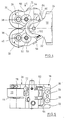
- a clamping body 10 for a thread rolling head 12 which has an L-shaped section 14, on one web of which a clamping pin 16 is attached to the outside.
- a rolling head holder 18 is attached in the rectangular recess of the L-shaped section 14. This consists of a plate-shaped part 20 and two fork arms, only one of which can be seen at 22.
- the plate-shaped section 20 is attached to the clamping body 10 by means of suitable fastening means sitting on a section of the L-shaped section 14 shown.
- the rolling head 12 has two fork-shaped rolling head arms 28, 30 which are designed as two-armed levers and which are rotatably supported by the arms 22 of the holder 18 about a common axis (see further figures in this regard). Threaded rollers 32, 36 are rotatably mounted between the fork arms of the arms 28, 30, specifically on an axis 38 or 40 made of hard metal. As can be seen, the right fork arm in Fig. 1 is wider than the left. This is due to the fact that a gear mechanism is arranged in the wider fork arm, a central gear wheel of the transmission, which couples both thread rollers 32, 36 to one another, is arranged on the common axis. In each case one pinion (not shown) of the transmission sits on the axis 38, 40 and interacts with the thread roller 32, 36 in a rotationally fixed manner.
- Fig. 2 shows, for example, the side view of the thread roll 32. It can be seen that two arc-segment-shaped claws 42, 44 are provided on the front side, which are opposite one another on both sides of a continuous bore 46. The arc length of the claws 42, 44 is the same, the claws are displaced relative to one another in the circumferential direction, so that a distance a is formed on one side and a distance b is formed on the other side between the ends of opposite claws 42, 44. The ends are shaped so that they lie on the legs of an angle c.
- the claws of the pinions, not shown, on the axles 38, 40 are of complementary shape.
- rollers 32, 36 By pushing the rollers 32, 36 in from the side, they can be installed in the arms 28, 30, with only a single rotational position of the thread rollers 32, 36 allowing installation.
- a position rotated by 180 ° would result, for example, in that the closer distance a would meet the closer distance of the claws of the pinions. Only with a reverse
- the claws can be brought into one another in the rotational position of the rollers.
- the claws are designed so that the bores 46 of the rollers 32, 36 are aligned with the bores of the built-in pinion when the ends of the interacting claws are properly seated, so that the axes 38, 40 after the insertion of the rollers 32, 36 without more can be inserted. It is no longer necessary to precisely align the rollers.
- Figs. 4 and 5 the tangential rolling head removed from the clamping body 10 can be seen in a side view.
- the disks 50, 52 support axles 54, 56 of the gear wheels of the transmission, which mesh with the pinions on the axles 38, 40.
- the disk 58 supports the common axis 60 about which the arms 28, 30 can be pivoted on the holder 18.
- Figs. 6 and 7 it can also be seen that the arms 28, 30 are not constructed identically, rather the roller head arm 28 is relatively short, while the other roller head arm 30 has a jaw portion 70 which extends to the short portion.
- the jaw portion 70 extends beyond the center plane that extends between the rollers 32, 36 through the common axis 60.
- an adjusting screw 72 is mounted obliquely to the center plane described in the upper roller head arm 28 in a corresponding threaded bore.
- the arms 28, 30 can be pivoted relative to one another about the common axis 60, as from the different positions in FIGS. 6 and 7.
- the distance between the rollers which are only indicated by dash-dotted lines in FIGS.
- a scale 74 is provided on the lower arm 30, which cooperates with a marking 76 on the plate 58 which is firmly connected to the axis 60 and to the arm 28, so that the marking on the scale 74 indicates the distance between the axes of the rollers 32 , 36 have each other.
- this setting is relatively rough.
- Fine adjustment is carried out with the aid of measuring balls 78, 80 on the outside of the arms 28, 30, the spacing of which can be measured using a suitable precision measuring instrument.
- a spring section 82 is also connected to the jaw section 70 and is inserted into the holding section 20 through a slot 84.
- the holding section has a bore 86 which supports a threaded spindle 88.
- the threaded spindle is acted upon on one side at 88 and also on the opposite side at 90 by a compression spring.
- the threaded spindle 88 has a threaded section 92 on which a nut-like slide 94 is seated, with which the attachment 82 cooperates.
- the slide 94 is rotatably guided through the slot 84, so that it turns when the spindle 88 is rotated in FIGS. 6 and 7 moved down and up. With the aid of this adjustment mechanism, the lower arm 30 can be pivoted in the desired manner.
- the upper arm 28 is also pivoted at the same time. This makes it possible to achieve a central position of the rolling head after, as shown for example in FIG. 7, the thread rolls 32, 36 have been given a predetermined distance from one another.
- the section 20 is covered by a plate 24 on the top, which is fastened with screws 26.
- Another plate 96 is located on the underside and is attached in the same way. Both plates 24, 96 have an opening 98, 100 for the passage of a tool for rotating the spindle 88.
- the arm 22 of the holder 18 has a scale 102 which interacts with a scale 104 on the disk 58.
- the disk 58 moves together with the arm 28, so that the center setting of the rolling head can be adjusted with the aid of the scale 102.
- Each scale line of both scales has a specific center distance between the thread rolls. If this is e.g. 36, then the lines marked 36 on both scales 102, 104 must be aligned with one another so that the center adjustment is present.
- scales corresponding to scales 74 or 102 and 104 are also provided on the opposite sides of the rolling head.
Landscapes
- Engineering & Computer Science (AREA)
- Mechanical Engineering (AREA)
- Reduction Rolling/Reduction Stand/Operation Of Reduction Machine (AREA)
- A Measuring Device Byusing Mechanical Method (AREA)
- Casting Or Compression Moulding Of Plastics Or The Like (AREA)
- Moulding By Coating Moulds (AREA)
- Lining Or Joining Of Plastics Or The Like (AREA)
- Rolling Contact Bearings (AREA)
- Valve-Gear Or Valve Arrangements (AREA)
Applications Claiming Priority (2)
| Application Number | Priority Date | Filing Date | Title |
|---|---|---|---|
| DE29610183U DE29610183U1 (de) | 1996-06-07 | 1996-06-07 | Tangentialrollkopf |
| DE29610183U | 1996-06-07 |
Publications (2)
| Publication Number | Publication Date |
|---|---|
| EP0811443A1 true EP0811443A1 (fr) | 1997-12-10 |
| EP0811443B1 EP0811443B1 (fr) | 2001-12-12 |
Family
ID=8025000
Family Applications (1)
| Application Number | Title | Priority Date | Filing Date |
|---|---|---|---|
| EP97107896A Expired - Lifetime EP0811443B1 (fr) | 1996-06-07 | 1997-05-15 | Tête de roulage tangentiel |
Country Status (4)
| Country | Link |
|---|---|
| US (1) | US5784912A (fr) |
| EP (1) | EP0811443B1 (fr) |
| DE (2) | DE29610183U1 (fr) |
| ES (1) | ES2168541T3 (fr) |
Cited By (2)
| Publication number | Priority date | Publication date | Assignee | Title |
|---|---|---|---|---|
| DE102004006125B3 (de) * | 2004-02-07 | 2005-05-25 | Fette Gmbh | Tangentialgewinderollkopf |
| CN105710595A (zh) * | 2016-04-11 | 2016-06-29 | 华纳圣龙(宁波)有限公司 | 一种轴的滚花对准装置 |
Families Citing this family (12)
| Publication number | Priority date | Publication date | Assignee | Title |
|---|---|---|---|---|
| US6721840B1 (en) | 2000-08-18 | 2004-04-13 | Triscend Corporation | Method and system for interfacing an integrated circuit to synchronous dynamic memory and static memory |
| DE20102471U1 (de) * | 2001-02-13 | 2001-04-26 | Wilhelm Fette Gmbh, 21493 Schwarzenbek | Gewinderollkopf |
| DE50104846D1 (de) * | 2001-11-07 | 2005-01-20 | Fette Gmbh | Tangential-Rollkopf |
| US6748779B2 (en) | 2002-09-30 | 2004-06-15 | C.J. Winter Machine Technologies, Inc. | Tangential rolling attachment for a machine tool |
| US9573184B2 (en) * | 2013-12-18 | 2017-02-21 | United Technologies Corporation | Deep rolling tool for processing blade root |
| US9421602B2 (en) | 2013-12-18 | 2016-08-23 | United Technologies Corporation | Machine for deep rolling tool positioning |
| US9573175B2 (en) * | 2013-12-18 | 2017-02-21 | United Technologies Corporation | Deep rolling tool for blade fatigue life enhancement |
| US9566638B2 (en) * | 2013-12-18 | 2017-02-14 | United Technologies Corporation | Deep rolling tool with force adjustment |
| CN105522325B (zh) * | 2014-10-21 | 2018-04-06 | 河北首鼎金属制品有限公司 | 用于制造磨球的设备和方法 |
| DE202016100891U1 (de) | 2016-02-19 | 2016-03-15 | Lmt Fette Werkzeugtechnik Gmbh & Co. Kg | Gewinderollkopf |
| ES2693578T3 (es) * | 2016-02-19 | 2018-12-12 | Lmt Fette Werkzeugtechnik Gmbh & Co. Kg | Cabezal tangencial para rodar roscas |
| EP3208011B1 (fr) | 2016-02-19 | 2020-04-01 | LMT Fette Werkzeugtechnik GmbH & Co. KG | Tete de roulage tangentielle |
Citations (6)
| Publication number | Priority date | Publication date | Assignee | Title |
|---|---|---|---|---|
| US2933955A (en) * | 1954-01-06 | 1960-04-26 | Sheffield Corp | Thread rolling device |
| SU487699A1 (ru) * | 1972-06-30 | 1975-10-15 | Центральное Проектно-Конструкторское И Технологическое Бюро | Головка дл тангенциального накатывани резьб |
| SU599900A1 (ru) * | 1976-06-11 | 1978-03-30 | Центральное Проектно-Конструкторское И Технологическое Бюро | Тангенциальна резьбонакатна головка |
| SU1098641A1 (ru) * | 1982-12-23 | 1984-06-23 | Киевский Ордена Ленина Политехнический Институт Им.50-Летия Великой Октябрьской Социалистической Революции | Тангенциальна резьбонакатна головка |
| SU1207598A1 (ru) * | 1983-04-08 | 1986-01-30 | Gronskij Karl | Тангенциальна резьбонакатна головка |
| DE9312116U1 (de) * | 1993-07-14 | 1993-10-14 | Gustav Wagner Maschinenfabrik GmbH & Co KG, 72760 Reutlingen | Tangentialrollkopf |
Family Cites Families (3)
| Publication number | Priority date | Publication date | Assignee | Title |
|---|---|---|---|---|
| DE2335651C3 (de) * | 1973-07-13 | 1980-11-06 | Wilhelm Fette Gmbh, 2053 Schwarzenbek | Radialwalzkopf |
| DE2944999C2 (de) * | 1979-11-08 | 1982-11-25 | Wilhelm Fette Gmbh, 2053 Schwarzenbek | Tangentialrollkopf |
| DE8126319U1 (de) * | 1981-09-10 | 1983-05-19 | Wilhelm Fette Gmbh, 2053 Schwarzenbek | Gewinderollkopf |
-
1996
- 1996-06-07 DE DE29610183U patent/DE29610183U1/de not_active Expired - Lifetime
-
1997
- 1997-05-15 DE DE59705736T patent/DE59705736D1/de not_active Expired - Lifetime
- 1997-05-15 ES ES97107896T patent/ES2168541T3/es not_active Expired - Lifetime
- 1997-05-15 EP EP97107896A patent/EP0811443B1/fr not_active Expired - Lifetime
- 1997-06-06 US US08/870,885 patent/US5784912A/en not_active Expired - Lifetime
Patent Citations (6)
| Publication number | Priority date | Publication date | Assignee | Title |
|---|---|---|---|---|
| US2933955A (en) * | 1954-01-06 | 1960-04-26 | Sheffield Corp | Thread rolling device |
| SU487699A1 (ru) * | 1972-06-30 | 1975-10-15 | Центральное Проектно-Конструкторское И Технологическое Бюро | Головка дл тангенциального накатывани резьб |
| SU599900A1 (ru) * | 1976-06-11 | 1978-03-30 | Центральное Проектно-Конструкторское И Технологическое Бюро | Тангенциальна резьбонакатна головка |
| SU1098641A1 (ru) * | 1982-12-23 | 1984-06-23 | Киевский Ордена Ленина Политехнический Институт Им.50-Летия Великой Октябрьской Социалистической Революции | Тангенциальна резьбонакатна головка |
| SU1207598A1 (ru) * | 1983-04-08 | 1986-01-30 | Gronskij Karl | Тангенциальна резьбонакатна головка |
| DE9312116U1 (de) * | 1993-07-14 | 1993-10-14 | Gustav Wagner Maschinenfabrik GmbH & Co KG, 72760 Reutlingen | Tangentialrollkopf |
Non-Patent Citations (5)
| Title |
|---|
| DATABASE WPI Section PQ Derwent World Patents Index; Class P52, AN 76-H1098X [25], XP002041997 * |
| FIRMENSCHRIFT: "WAGNER Seitenrollwerkzeuge Nr. 8-300", September 1979, GUSTAV WAGNER MASCHINENFABRIK, REUTLINGEN, DE, XP002041994 * |
| SOVIET INVENTIONS ILLUSTRATED Section PQ Week 07, 28 March 1979 Derwent World Patents Index; Class P52, AN B4565B, XP002041996 * |
| SOVIET INVENTIONS ILLUSTRATED Section PQ Week 8505, 13 March 1985 Derwent World Patents Index; Class P52, AN 85-030182, XP002041998 * |
| SOVIET INVENTIONS ILLUSTRATED Section PQ Week 8637, 26 September 1986 Derwent World Patents Index; Class P52, AN 86-243912, XP002041995 * |
Cited By (3)
| Publication number | Priority date | Publication date | Assignee | Title |
|---|---|---|---|---|
| DE102004006125B3 (de) * | 2004-02-07 | 2005-05-25 | Fette Gmbh | Tangentialgewinderollkopf |
| EP1561525A3 (fr) * | 2004-02-07 | 2005-11-09 | Fette GmbH | Tête de roulage des filets tangentiels |
| CN105710595A (zh) * | 2016-04-11 | 2016-06-29 | 华纳圣龙(宁波)有限公司 | 一种轴的滚花对准装置 |
Also Published As
| Publication number | Publication date |
|---|---|
| DE29610183U1 (de) | 1997-10-02 |
| ES2168541T3 (es) | 2002-06-16 |
| EP0811443B1 (fr) | 2001-12-12 |
| US5784912A (en) | 1998-07-28 |
| DE59705736D1 (de) | 2002-01-24 |
Similar Documents
| Publication | Publication Date | Title |
|---|---|---|
| DE102014016630B4 (de) | Verstelleinrichtung für eine Druckrolle einer Bearbeitungsmaschine, insbesondere Kehlmaschine, sowie Bearbeitsmaschine, insbesondere Kehlmaschine, mit einer solchen Verstelleinrichtung | |
| EP0811443B1 (fr) | Tête de roulage tangentiel | |
| EP0859730B1 (fr) | Dispositif de pliage | |
| EP2886223B1 (fr) | Tête à rouler les filets | |
| DE2720673B2 (de) | Vorrichtung zum ungleichförmigen Spannen eines Gummituches in einer Offsetdruckmaschine | |
| DD291488A5 (de) | Doppelrolleneinfuehrarmatur | |
| DE9312116U1 (de) | Tangentialrollkopf | |
| EP0416167B1 (fr) | Dispositif d'affûtage d'une hélice | |
| DE3242765A1 (de) | Planfraeskopf mit einstellbarer planschlichtschneide | |
| DE3026513C2 (de) | Werkzeug zum Aufbohren und Plansenken | |
| EP1445049A1 (fr) | Outil de moletage | |
| DE2753284C2 (de) | Schmitzringanordnung zwischen zwei Druckwerkszylindern | |
| DE3232689C2 (de) | Vorrichtung zum Schleifen von gerad- und wendelgenuteten Schneidwerkzeugen | |
| DE2623825A1 (de) | Rippenwalzwerk zum verarbeiten von tabakrippen | |
| DE10035001B4 (de) | Leitwalze | |
| DD278538A5 (de) | Einrichtung zur steuerung der werkzeugstellung in abhaengigkeit von der hubposition | |
| WO1994002275A1 (fr) | Tete d'outil radialement ajustable, notamment pour travaux de tournage et d'alesage | |
| EP1310309B1 (fr) | Tête de roulage tangentiel | |
| DE1925695B2 (de) | Manuell betätigbares Werkzeug zum Biegen und Schneiden von Stäben und Drähten | |
| EP1561525B1 (fr) | Tête de roulage des filets tangentiel | |
| DE1477040A1 (de) | Werkzeughalter fuer Walzwerkzeuge | |
| EP0727271A1 (fr) | Dispositif pour l'ajustement fine de la position latérale d'une lame de scie à inciser sur une scie circulaire | |
| DE3201489C2 (fr) | ||
| DE9305070U1 (de) | Maschine zur Herstellung eines Rohrstutzens | |
| DE3707246C2 (fr) |
Legal Events
| Date | Code | Title | Description |
|---|---|---|---|
| PUAI | Public reference made under article 153(3) epc to a published international application that has entered the european phase |
Free format text: ORIGINAL CODE: 0009012 |
|
| AK | Designated contracting states |
Kind code of ref document: A1 Designated state(s): BE DE ES FR GB IT NL |
|
| 17P | Request for examination filed |
Effective date: 19971104 |
|
| 17Q | First examination report despatched |
Effective date: 20000428 |
|
| GRAG | Despatch of communication of intention to grant |
Free format text: ORIGINAL CODE: EPIDOS AGRA |
|
| GRAG | Despatch of communication of intention to grant |
Free format text: ORIGINAL CODE: EPIDOS AGRA |
|
| GRAH | Despatch of communication of intention to grant a patent |
Free format text: ORIGINAL CODE: EPIDOS IGRA |
|
| GRAH | Despatch of communication of intention to grant a patent |
Free format text: ORIGINAL CODE: EPIDOS IGRA |
|
| GRAA | (expected) grant |
Free format text: ORIGINAL CODE: 0009210 |
|
| AK | Designated contracting states |
Kind code of ref document: B1 Designated state(s): BE DE ES FR GB IT NL |
|
| REG | Reference to a national code |
Ref country code: GB Ref legal event code: IF02 |
|
| GBT | Gb: translation of ep patent filed (gb section 77(6)(a)/1977) |
Effective date: 20011212 |
|
| REF | Corresponds to: |
Ref document number: 59705736 Country of ref document: DE Date of ref document: 20020124 |
|
| ET | Fr: translation filed | ||
| REG | Reference to a national code |
Ref country code: ES Ref legal event code: FG2A Ref document number: 2168541 Country of ref document: ES Kind code of ref document: T3 |
|
| RAP2 | Party data changed (patent owner data changed or rights of a patent transferred) |
Owner name: FETTE GMBH |
|
| NLT2 | Nl: modifications (of names), taken from the european patent patent bulletin |
Owner name: FETTE GMBH |
|
| PLBE | No opposition filed within time limit |
Free format text: ORIGINAL CODE: 0009261 |
|
| STAA | Information on the status of an ep patent application or granted ep patent |
Free format text: STATUS: NO OPPOSITION FILED WITHIN TIME LIMIT |
|
| 26N | No opposition filed | ||
| NLT1 | Nl: modifications of names registered in virtue of documents presented to the patent office pursuant to art. 16 a, paragraph 1 |
Owner name: FETTE GMBH |
|
| REG | Reference to a national code |
Ref country code: DE Ref legal event code: R082 Ref document number: 59705736 Country of ref document: DE Representative=s name: HAUCK PATENT- UND RECHTSANWAELTE, DE |
|
| PGFP | Annual fee paid to national office [announced via postgrant information from national office to epo] |
Ref country code: NL Payment date: 20130523 Year of fee payment: 17 Ref country code: BE Payment date: 20130521 Year of fee payment: 17 |
|
| REG | Reference to a national code |
Ref country code: NL Ref legal event code: V1 Effective date: 20141201 |
|
| PG25 | Lapsed in a contracting state [announced via postgrant information from national office to epo] |
Ref country code: NL Free format text: LAPSE BECAUSE OF NON-PAYMENT OF DUE FEES Effective date: 20141201 |
|
| REG | Reference to a national code |
Ref country code: FR Ref legal event code: PLFP Year of fee payment: 20 |
|
| PGFP | Annual fee paid to national office [announced via postgrant information from national office to epo] |
Ref country code: GB Payment date: 20160523 Year of fee payment: 20 Ref country code: ES Payment date: 20160523 Year of fee payment: 20 |
|
| PGFP | Annual fee paid to national office [announced via postgrant information from national office to epo] |
Ref country code: FR Payment date: 20160523 Year of fee payment: 20 Ref country code: IT Payment date: 20160530 Year of fee payment: 20 |
|
| PGFP | Annual fee paid to national office [announced via postgrant information from national office to epo] |
Ref country code: DE Payment date: 20160714 Year of fee payment: 20 |
|
| REG | Reference to a national code |
Ref country code: DE Ref legal event code: R071 Ref document number: 59705736 Country of ref document: DE |
|
| REG | Reference to a national code |
Ref country code: GB Ref legal event code: PE20 Expiry date: 20170514 |
|
| PG25 | Lapsed in a contracting state [announced via postgrant information from national office to epo] |
Ref country code: GB Free format text: LAPSE BECAUSE OF EXPIRATION OF PROTECTION Effective date: 20170514 Ref country code: BE Free format text: LAPSE BECAUSE OF NON-PAYMENT OF DUE FEES Effective date: 20140531 |
|
| REG | Reference to a national code |
Ref country code: ES Ref legal event code: FD2A Effective date: 20170825 |
|
| PG25 | Lapsed in a contracting state [announced via postgrant information from national office to epo] |
Ref country code: ES Free format text: LAPSE BECAUSE OF EXPIRATION OF PROTECTION Effective date: 20170516 |