EP0811459B1 - Schwenkantrieb - Google Patents
Schwenkantrieb Download PDFInfo
- Publication number
- EP0811459B1 EP0811459B1 EP97108380A EP97108380A EP0811459B1 EP 0811459 B1 EP0811459 B1 EP 0811459B1 EP 97108380 A EP97108380 A EP 97108380A EP 97108380 A EP97108380 A EP 97108380A EP 0811459 B1 EP0811459 B1 EP 0811459B1
- Authority
- EP
- European Patent Office
- Prior art keywords
- pivot
- drive
- axle
- working cylinders
- articulated
- Prior art date
- Legal status (The legal status is an assumption and is not a legal conclusion. Google has not performed a legal analysis and makes no representation as to the accuracy of the status listed.)
- Expired - Lifetime
Links
- 239000007787 solid Substances 0.000 claims 1
- 238000000034 method Methods 0.000 description 3
- 238000004091 panning Methods 0.000 description 2
- 238000013016 damping Methods 0.000 description 1
- 238000003754 machining Methods 0.000 description 1
Images




Classifications
-
- B—PERFORMING OPERATIONS; TRANSPORTING
- B23—MACHINE TOOLS; METAL-WORKING NOT OTHERWISE PROVIDED FOR
- B23Q—DETAILS, COMPONENTS, OR ACCESSORIES FOR MACHINE TOOLS, e.g. ARRANGEMENTS FOR COPYING OR CONTROLLING; MACHINE TOOLS IN GENERAL CHARACTERISED BY THE CONSTRUCTION OF PARTICULAR DETAILS OR COMPONENTS; COMBINATIONS OR ASSOCIATIONS OF METAL-WORKING MACHINES, NOT DIRECTED TO A PARTICULAR RESULT
- B23Q3/00—Devices holding, supporting, or positioning work or tools, of a kind normally removable from the machine
- B23Q3/155—Arrangements for automatic insertion or removal of tools, e.g. combined with manual handling
- B23Q3/157—Arrangements for automatic insertion or removal of tools, e.g. combined with manual handling of rotary tools
- B23Q3/15713—Arrangements for automatic insertion or removal of tools, e.g. combined with manual handling of rotary tools a transfer device taking a single tool from a storage device and inserting it in a spindle
- B23Q3/1572—Arrangements for automatic insertion or removal of tools, e.g. combined with manual handling of rotary tools a transfer device taking a single tool from a storage device and inserting it in a spindle the storage device comprising rotating or circulating storing means
- B23Q3/15722—Rotary discs or drums
-
- B—PERFORMING OPERATIONS; TRANSPORTING
- B23—MACHINE TOOLS; METAL-WORKING NOT OTHERWISE PROVIDED FOR
- B23Q—DETAILS, COMPONENTS, OR ACCESSORIES FOR MACHINE TOOLS, e.g. ARRANGEMENTS FOR COPYING OR CONTROLLING; MACHINE TOOLS IN GENERAL CHARACTERISED BY THE CONSTRUCTION OF PARTICULAR DETAILS OR COMPONENTS; COMBINATIONS OR ASSOCIATIONS OF METAL-WORKING MACHINES, NOT DIRECTED TO A PARTICULAR RESULT
- B23Q5/00—Driving or feeding mechanisms; Control arrangements therefor
- B23Q5/22—Feeding members carrying tools or work
- B23Q5/26—Fluid-pressure drives
-
- B—PERFORMING OPERATIONS; TRANSPORTING
- B23—MACHINE TOOLS; METAL-WORKING NOT OTHERWISE PROVIDED FOR
- B23Q—DETAILS, COMPONENTS, OR ACCESSORIES FOR MACHINE TOOLS, e.g. ARRANGEMENTS FOR COPYING OR CONTROLLING; MACHINE TOOLS IN GENERAL CHARACTERISED BY THE CONSTRUCTION OF PARTICULAR DETAILS OR COMPONENTS; COMBINATIONS OR ASSOCIATIONS OF METAL-WORKING MACHINES, NOT DIRECTED TO A PARTICULAR RESULT
- B23Q16/00—Equipment for precise positioning of tool or work into particular locations not otherwise provided for
- B23Q16/02—Indexing equipment
- B23Q16/022—Indexing equipment in which only the indexing movement is of importance
- B23Q16/026—Indexing equipment in which only the indexing movement is of importance by converting a reciprocating or oscillating movement into a rotary indexing movement
-
- B—PERFORMING OPERATIONS; TRANSPORTING
- B23—MACHINE TOOLS; METAL-WORKING NOT OTHERWISE PROVIDED FOR
- B23Q—DETAILS, COMPONENTS, OR ACCESSORIES FOR MACHINE TOOLS, e.g. ARRANGEMENTS FOR COPYING OR CONTROLLING; MACHINE TOOLS IN GENERAL CHARACTERISED BY THE CONSTRUCTION OF PARTICULAR DETAILS OR COMPONENTS; COMBINATIONS OR ASSOCIATIONS OF METAL-WORKING MACHINES, NOT DIRECTED TO A PARTICULAR RESULT
- B23Q3/00—Devices holding, supporting, or positioning work or tools, of a kind normally removable from the machine
- B23Q3/155—Arrangements for automatic insertion or removal of tools, e.g. combined with manual handling
- B23Q3/1552—Arrangements for automatic insertion or removal of tools, e.g. combined with manual handling parts of devices for automatically inserting or removing tools
- B23Q3/15526—Storage devices; Drive mechanisms therefor
-
- F—MECHANICAL ENGINEERING; LIGHTING; HEATING; WEAPONS; BLASTING
- F15—FLUID-PRESSURE ACTUATORS; HYDRAULICS OR PNEUMATICS IN GENERAL
- F15B—SYSTEMS ACTING BY MEANS OF FLUIDS IN GENERAL; FLUID-PRESSURE ACTUATORS, e.g. SERVOMOTORS; DETAILS OF FLUID-PRESSURE SYSTEMS, NOT OTHERWISE PROVIDED FOR
- F15B15/00—Fluid-actuated devices for displacing a member from one position to another; Gearing associated therewith
- F15B15/02—Mechanical layout characterised by the means for converting the movement of the fluid-actuated element into movement of the finally-operated member
- F15B15/06—Mechanical layout characterised by the means for converting the movement of the fluid-actuated element into movement of the finally-operated member for mechanically converting rectilinear movement into non- rectilinear movement
-
- F—MECHANICAL ENGINEERING; LIGHTING; HEATING; WEAPONS; BLASTING
- F16—ENGINEERING ELEMENTS AND UNITS; GENERAL MEASURES FOR PRODUCING AND MAINTAINING EFFECTIVE FUNCTIONING OF MACHINES OR INSTALLATIONS; THERMAL INSULATION IN GENERAL
- F16H—GEARING
- F16H21/00—Gearings comprising primarily only links or levers, with or without slides
- F16H21/10—Gearings comprising primarily only links or levers, with or without slides all movement being in, or parallel to, a single plane
- F16H21/44—Gearings comprising primarily only links or levers, with or without slides all movement being in, or parallel to, a single plane for conveying or interconverting oscillating or reciprocating motions
Definitions
- the invention relates to a swivel drive for swiveling a tool store with several tool places distributed around the swivel axis, with two parallel ones swivel axles fixed to the frame, around the first of which a first double-acting Working cylinder and around the second a first pivot lever is mounted on the supports the first double-acting cylinder articulated.
- the swivel drive consisting of a pinion, a rack and a hydraulic piston, wherein the rotatably mounted column receiving the storage locations stops assigned.
- this rack and pinion drive is complex and backlash-prone, only two swivel positions offset by 180 degrees can be set.
- a well-known rotary memory with four positions offset by 90 degrees each (EP 0 224 714 A1) is replaced by a frame-bound rotating cylinder Freewheel driven. It rotates 90 degrees per stroke. Its respective rotary end position is defined by a detent. Is z. B. the rotary memory at 0 degrees and is for the The next machining operation requires a position of 270 degrees, the rotary cylinder can be controlled three times in succession. That takes time to process get lost.
- the invention is based, a swivel drive according to the task Generic preamble of claim 1 to create a defined and simple structure quick adjustment of the swivel positions allowed.
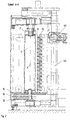
- the tool magazine (Fig. 1, 2) has two tool towers 2, the square of which Store columns 4 in the lower and upper support of a frame 6 and on each its four long sides accommodate a bar 8 with tool positions 10, which means Swivel drives S in four swivel positions, each offset by 90 degrees are pivotable.
- a rearward-facing position over the column 4 protruding strips 8 are the tool places 10 by hand or by means of a can be equipped with internal tool management system.
- the tool places 10 in the access one Handling device H which in turn is the work spindle, not shown Machine tool or a changing device assigned to the work spindle served.
- the handling device H has a straight articulated arm H1, the one guided horizontally on the upper and lower supports of the frame 6 Column H2 can be moved vertically
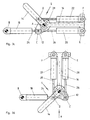
- the particularly flat swivel drive S has three swivel levers 12, 14, 16 and three double-acting working cylinders 18, 20, 22 damped on both sides on.
- the pivot levers 12, 14, 16 have a common fixed space Pivot axis A
- the working cylinder 18 has a fixed pivot axis B.
- the Swivel lever 16 is T-shaped.
- the hinge axis C connects the Swivel lever 12 with the pistons 24 and 26 of the working cylinders 18 and 20, the Hinge axis D, the pivot lever 14 which can be coupled to the column 4 and the piston 28 of the working cylinder 22, the hinge axis E the pivot lever 16 with the Working cylinder 20 and the hinge axis F the pivot lever 16 with the Working cylinder 22.
- the working cylinder 18 lies in a first one, the working cylinders 20, 22 lie in a common second pivot plane. All working cylinders 18, 20, 22 are identical and in particular have the same stroke. In the swivel positions the swivel levers 12 and 14 each close angles of 90 Degree one, the working cylinders 20, 22 and the pivot lever 16 are parallel to each other.
- Control devices, not shown, for the control For example, directional valves, provided a first for the control of the Working cylinder 18 and a second for the parallel control of the working cylinder 20 and 22.
- the mode of operation is as follows: in the starting position according to FIG. 3a, all pistons 24, 26, 28 are retracted. 3b, the piston 24 of the working cylinder 18 is extended so that the pivot levers 12, 14, 16 rotate counterclockwise by 90 degrees while maintaining their mutual position. In order to reach the position according to FIG. 3c from the starting position according to FIG. 3a, the pistons 26 and 28 working cylinders 20 and 22 are simultaneously extended so that the pivot levers 16 and 14 rotate by 90 and 180 degrees, respectively. The total angle of rotation of the pivoting lever 14 results from the sum of the angles of rotation by which the pivoting levers 16 and 14 rotate relative to their respectively adjacent pivoting levers 12 and 16, respectively.
- the total speed of the pivot angle 14 results from the sum of the speeds at which the pivot levers 16, 14 rotate relative to their respectively adjacent pivot levers 12 and 16, respectively.
- all pistons 24, 26, 28 are extended simultaneously, so that the pivot levers 12, 16 and 14 rotate through 90, 180 and 270 degrees.
- the total pivot angle and the total speed of the pivot lever 14 result, as above, from the sum of the individual angles and individual speeds.
- Each pivot position of the pivot lever 14 is assigned a control pattern for the simultaneous control of the working cylinders 18, 20, 22: Working cylinder 18th Working cylinder 20 Working cylinder 22 0 degrees Retract the piston Retract the piston Retract the piston 90 degrees Extend the piston Retract the piston Retract the piston 180 degrees Retract the piston Extend the piston Extend the piston 270 degrees Extend the piston Extend the piston Extend the piston
- the working cylinders 20 and 22 can be controlled in the same way for each swivel position. They form a group, which a common control device, i. H. on common directional control valve is assigned. All panning operations, whether z. B. from 0 degrees to 270 degrees or from 180 degrees to 270 degrees, run continuously and in the same time.
- the associated speed profiles are shown in FIG. 5.
- the exemplary embodiment according to FIG. 6 is provided for a series of tool magazines, each with a different number of vertical tool rows.
- all swivel levers 12, 30'-30 “" and all working cylinders 18, 32'-32 “” are of identical design.
- Each swivel lever has only one joint axis G.
- the distances between the pivot axis B and the hinge axes G from the pivot axis A are also the same.
- six swivel positions can be set.
- the first three working cylinders 18, 32 'and 32 can be controlled in parallel. They form one Group to which a common directional control valve is assigned. However, it can also set up other control patterns in which the last three working cylinders 32 " up to 32 '"' or the two outer working cylinders can be controlled in parallel.
- n Swing levers and n working cylinders form a swivel drive with n + 1 Swivel positions.
- Each swivel position is a specific control pattern assigned, after which all working cylinders are controlled simultaneously.
- the Panning processes run continuously and in the same time, regardless of this which start position is pivoted into which end position, d. H. which one Swivel angle is covered. They are quick and easy Tool change possible.
- the working cylinders are individual or in groups controllable. There are 2 for up to 4 swivel positions and 3 for up to 8 swivel positions and 4 control devices are sufficient for up to 16 swivel positions.
Landscapes
- Engineering & Computer Science (AREA)
- Mechanical Engineering (AREA)
- General Engineering & Computer Science (AREA)
- Physics & Mathematics (AREA)
- Fluid Mechanics (AREA)
- Manipulator (AREA)
- Earth Drilling (AREA)
Description
- Fig. 1
- ein Werkzeugmagazin mit zwei drehbar gelagerten Werkzeugtürmen
- Fig. 2
- einen Werkzeugturm mit erfindungsgemäßem Schwenkantrieb im Schnitt
- Fig. 3a-d
- den schematisch dargestellten Schwenkantrieb in vier Schwenkstellungen
- Fig. 4
- eine Ansicht auf Fig. 3d in Richtung des Pfeils X
- Fig. 5
- die den Schwenkvorgängen zugeordneten Geschwindigkeitsverläufe
- Fig. 6
- eine weitere Ausbildung des erfindungsgemäßen Schwenkantriebs
| Arbeitszylinder 18 | Arbeitszylinder 20 | Arbeitszylinder 22 | |
| 0 Grad | Kolben einfahren | Kolben einfahren | Kolben einfahren |
| 90 Grad | Kolben ausfahren | Kolben einfahren | Kolben einfahren |
| 180 Grad | Kolben einfahren | Kolben ausfahren | Kolben ausfahren |
| 270 Grad | Kolben ausfahren | Kolben ausfahren | Kolben ausfahren |
Die Abstände der Schwenkachse B und der Gelenkachsen G von der Schwenkachse A sind ebenfalls gleich. Mit diesem Schwenkantrieb lassen sich sechs Schwenkstellungen einstellen. Mögliche Ansteuerungsmuster dafür sind:
| AZ 18 | AZ 32' | AZ 32" | AZ 32'" | AZ 32"" | |
| 0 Grad | einfahren | einfahren | einfahren | einfahren | einfahren |
| 2. Stellung | einfahren | einfahren | einfahren | einfahren | ausfahren |
| 3. Stellung | einfahren | einfahren | einfahren | ausfahren | ausfahren |
| 4. Stellung | ausfahren | ausfahren | ausfahren | einfahren | einfahren |
| 5. Stellung | ausfahren | ausfahren | ausfahren | ausfahren | einfahren |
| 6. Stellung | ausfahren | ausfahren | ausfahren | ausfahren | ausfahren |
Claims (9)
- Schwenkantrieb zum Schwenken eines Werkzeugspeichers mit mehreren um die Schwenkachse verteilten Werkzeugplätzen, mitzwei parallelen gestellfesten Schwenkachsen, um deren erste (B) ein erster doppeltwirkender Arbeitszylinder (18) und um deren zweite (A) ein erster Schwenkhebel (12) lagert, der sich an dem ersten doppeltwirkenden Arbeitszylinder (18) gelenkig abstützt, gekennzeichnet dadurch, dassein oder mehrere um die zweite Schwenkachse (A) lagernde zweite Schwenkhebel (14, 16, 30) vorgesehen sind, an denen je ein zweiter doppeltwirkender Arbeitszylinder (20, 22, 32) angelenkt ist, der sich an dem jeweils benachbarten Schwenkhebel gelenkig abstützt, wobeiden Schwenkstellungen je ein Ansteuerungsmuster für die gleichzeitige Ansteuerung der Arbeitszylinder (18, 20, 22, 32) zuordenbar ist
- Schwenkantrieb nach Anspruch 1, gekennzeichnet dadurch, dass drei Schwenkhebel (12, 14, 16, 30) und drei Arbeitszylinder (18, 20, 22, 32) einen Schwenkantrieb mit vier vorzugsweise um jeweils 90 Grad versetzten Schwenkstellungen bilden.
- Schwenkantrieb nach Anspruch 1 oder 2, gekennzeichnet dadurch, dass die Arbeitszylinder (18, 20, 22, 32) einzeln oder gruppenweise ansteuerbar sind.
- Schwenkantrieb nach einem der Ansprüche von 1 bis 3, gekennzeichnet dadurch, dass einzelnen Arbeitszylindem (18, 32) oder Arbeitszylindergrupppen (20, 22, 32) je eine Schwenkebene zugeordnet ist.
- Schwenkantrieb nach einem der Ansprüche von 1 bis 4, gekennzeichnet dadurch, dass die Gelenkachsen (G) auf einem um die zweite Schwenkachse (A) verlaufenden und die erste Schwenkachse (B) einschließenden Kreisbogen liegen.
- Schwenkantrieb nach einem der Ansprüche von 2 bis 4, gekennzeichnet dadurch, dass die getrennten Gelenkachsen (E, F) des T -förmig ausgebildeten mittleren Schwenkhebels (16) auf einem um die zweite Schwenkachse (A) verlaufenden und die erste Schwenkachse (B) einschließenden äußeren Kreisbogen und die Gelenkachsen (C, D) der äußeren Schwenkhebel (12, 14) auf einem um die zweite Schwenkachse (A) verlaufenden inneren Kreisbogen liegen, wobei in den um jeweils 90 Grad versetzten Schwenkstellungen der zweite und der dritte Arbeitszylinder (20, 22) parallel zueinander verlaufen und die äußeren Schwenkhebel (12, 14) jeweils Winkel von 90 Grad einschließen.
- Schwenkantrieb nach einem der Ansprüche von 1 bis 6, gekennzeichnet dadurch, dass die Arbeitszylinder (18, 20, 22, 32) beidseitig endlagengedämpft sind.
- Schwenkantrieb nach einem der Ansprüche von 1 bis 7, gekennzeichnet dadurch, dass die Arbeitszylinder (18, 20, 22, 32) den gleichen Hub besitzen.
- Schwenkantrieb nach einem der Ansprüche von 1 bis 8, gekennzeichnet dadurch, dass die Arbeitszylinder (18, 20, 22, 32) gleich ausgebildet sind.
Applications Claiming Priority (2)
| Application Number | Priority Date | Filing Date | Title |
|---|---|---|---|
| DE19622227 | 1996-06-03 | ||
| DE19622227A DE19622227C2 (de) | 1996-06-03 | 1996-06-03 | Schwenkantrieb |
Publications (2)
| Publication Number | Publication Date |
|---|---|
| EP0811459A1 EP0811459A1 (de) | 1997-12-10 |
| EP0811459B1 true EP0811459B1 (de) | 2001-12-19 |
Family
ID=7796003
Family Applications (1)
| Application Number | Title | Priority Date | Filing Date |
|---|---|---|---|
| EP97108380A Expired - Lifetime EP0811459B1 (de) | 1996-06-03 | 1997-05-23 | Schwenkantrieb |
Country Status (2)
| Country | Link |
|---|---|
| EP (1) | EP0811459B1 (de) |
| DE (2) | DE19622227C2 (de) |
Families Citing this family (2)
| Publication number | Priority date | Publication date | Assignee | Title |
|---|---|---|---|---|
| CN106812735B (zh) * | 2017-02-13 | 2018-08-17 | 德迈智能装备有限公司 | 一种双缸液压旋转装置的控制方法 |
| CN109998809B (zh) * | 2019-04-23 | 2024-10-11 | 恩比尔(厦门)机械制造有限公司 | 带有保险装置的轮椅电动车头用电动提升机构 |
Family Cites Families (6)
| Publication number | Priority date | Publication date | Assignee | Title |
|---|---|---|---|---|
| DD78175A (de) * | ||||
| GB1080074A (en) * | 1963-04-11 | 1967-08-23 | Elliott Brothers London Ltd | Improvements in mechanical positioning systems |
| US3720138A (en) * | 1971-02-04 | 1973-03-13 | Helmerich & Payne | Operator |
| DE8531303U1 (de) * | 1985-11-06 | 1987-08-13 | Schmoll Maschinen GmbH, Werkzeug- und Vorrichtungsbau, 6242 Kronberg | Speicherplatte für Werkzeugmaschine |
| FR2633365B1 (fr) * | 1988-06-23 | 1990-08-24 | Egretier Jean Michel | Dispositif articule d'entrainement en rotation d'une piece d'une valeur angulaire bien determinee |
| US5083453A (en) * | 1990-02-01 | 1992-01-28 | Mts Systems Corporation | Linkage for vehicle simulator |
-
1996
- 1996-06-03 DE DE19622227A patent/DE19622227C2/de not_active Expired - Fee Related
-
1997
- 1997-05-23 DE DE59705846T patent/DE59705846D1/de not_active Expired - Lifetime
- 1997-05-23 EP EP97108380A patent/EP0811459B1/de not_active Expired - Lifetime
Also Published As
| Publication number | Publication date |
|---|---|
| DE19622227A1 (de) | 1997-12-04 |
| DE59705846D1 (de) | 2002-01-31 |
| EP0811459A1 (de) | 1997-12-10 |
| DE19622227C2 (de) | 1999-06-02 |
Similar Documents
| Publication | Publication Date | Title |
|---|---|---|
| EP1313575B1 (de) | Gelenkarm-transportsystem | |
| EP3579987B1 (de) | Biegewerkzeug-speichervorrichtung und verfahren zum beschicken einer biegepresse | |
| EP0812652B1 (de) | Vorrichtung zur Bearbeitung und/oder Montage von Werkstücken | |
| DE102009031202A1 (de) | Werkzeugmaschine mit einer Werkzeugwechselvorrichtung | |
| DE4408450A1 (de) | Transporteinrichtung für Werkstücke in einer Presse | |
| EP1170218A1 (de) | Greifvorrichtung für dünne, plattenförmige Teile | |
| EP1426137A2 (de) | Werkzeugmaschine | |
| EP2897764B1 (de) | Werkstückwechsler und werkzeugmaschine mit einem solchen werkstückwechsler | |
| EP0331178B1 (de) | Kompaktaufbau einer Säulenbohrmaschine | |
| EP2289665B1 (de) | Werkzeugmaschine mit einer Werkzeugwechselvorrichtung | |
| DE1183020B (de) | Stapelvorrichtung fuer profiliertes Walzgut | |
| DE2102860C3 (de) | Bearbeitungszentrum mit einer um eine horizontale Achse rotierbaren Speichertrommel | |
| CH632442A5 (en) | Manipulator | |
| DE19622227C2 (de) | Schwenkantrieb | |
| DE19616431C2 (de) | Werkzeugmaschine mit in Magazinposition geneigt angeordneten Werkzeughaltern | |
| DE3631718A1 (de) | Ladeeinrichtung mit ladekreuz | |
| EP0779126B1 (de) | Werkzeugmaschine mit mehreren Antriebseinheiten | |
| EP0847818B1 (de) | Transferpresse | |
| EP0640432B1 (de) | Werkzeugmaschine | |
| DE2850472C2 (de) | ||
| DE19906712C2 (de) | Einrichtung zum Wechseln von Werkzeugen und/oder Werkstücken | |
| WO1999016576A1 (de) | Werkzeugmaschine | |
| EP0461598B1 (de) | Werkzeugmaschine | |
| DE3410601A1 (de) | Greifer fuer industrieroboter | |
| EP0102547A2 (de) | Transportautomat, insbesondere zur Pressenverkettung |
Legal Events
| Date | Code | Title | Description |
|---|---|---|---|
| PUAI | Public reference made under article 153(3) epc to a published international application that has entered the european phase |
Free format text: ORIGINAL CODE: 0009012 |
|
| AK | Designated contracting states |
Kind code of ref document: A1 Designated state(s): DE FR IT SE |
|
| 17P | Request for examination filed |
Effective date: 19980421 |
|
| 17Q | First examination report despatched |
Effective date: 20010309 |
|
| GRAG | Despatch of communication of intention to grant |
Free format text: ORIGINAL CODE: EPIDOS AGRA |
|
| GRAG | Despatch of communication of intention to grant |
Free format text: ORIGINAL CODE: EPIDOS AGRA |
|
| GRAH | Despatch of communication of intention to grant a patent |
Free format text: ORIGINAL CODE: EPIDOS IGRA |
|
| GRAH | Despatch of communication of intention to grant a patent |
Free format text: ORIGINAL CODE: EPIDOS IGRA |
|
| GRAA | (expected) grant |
Free format text: ORIGINAL CODE: 0009210 |
|
| AK | Designated contracting states |
Kind code of ref document: B1 Designated state(s): DE FR IT SE |
|
| PG25 | Lapsed in a contracting state [announced via postgrant information from national office to epo] |
Ref country code: FR Free format text: LAPSE BECAUSE OF FAILURE TO SUBMIT A TRANSLATION OF THE DESCRIPTION OR TO PAY THE FEE WITHIN THE PRESCRIBED TIME-LIMIT Effective date: 20011219 |
|
| REF | Corresponds to: |
Ref document number: 59705846 Country of ref document: DE Date of ref document: 20020131 |
|
| PG25 | Lapsed in a contracting state [announced via postgrant information from national office to epo] |
Ref country code: SE Free format text: LAPSE BECAUSE OF FAILURE TO SUBMIT A TRANSLATION OF THE DESCRIPTION OR TO PAY THE FEE WITHIN THE PRESCRIBED TIME-LIMIT Effective date: 20020319 |
|
| PG25 | Lapsed in a contracting state [announced via postgrant information from national office to epo] |
Ref country code: DE Free format text: LAPSE BECAUSE OF THE APPLICANT RENOUNCES Effective date: 20020513 |
|
| EN | Fr: translation not filed | ||
| PLBE | No opposition filed within time limit |
Free format text: ORIGINAL CODE: 0009261 |
|
| STAA | Information on the status of an ep patent application or granted ep patent |
Free format text: STATUS: NO OPPOSITION FILED WITHIN TIME LIMIT |
|
| 26N | No opposition filed | ||
| PG25 | Lapsed in a contracting state [announced via postgrant information from national office to epo] |
Ref country code: IT Free format text: LAPSE BECAUSE OF NON-PAYMENT OF DUE FEES Effective date: 20050523 |