EP0811487A2 - System zum Aufziehen von Druckplatten und Verfahren zu dessen Anwendung - Google Patents
System zum Aufziehen von Druckplatten und Verfahren zu dessen Anwendung Download PDFInfo
- Publication number
- EP0811487A2 EP0811487A2 EP97850088A EP97850088A EP0811487A2 EP 0811487 A2 EP0811487 A2 EP 0811487A2 EP 97850088 A EP97850088 A EP 97850088A EP 97850088 A EP97850088 A EP 97850088A EP 0811487 A2 EP0811487 A2 EP 0811487A2
- Authority
- EP
- European Patent Office
- Prior art keywords
- printing plate
- plate
- cylinder
- pressure roller
- support surface
- Prior art date
- Legal status (The legal status is an assumption and is not a legal conclusion. Google has not performed a legal analysis and makes no representation as to the accuracy of the status listed.)
- Withdrawn
Links
- 238000007639 printing Methods 0.000 title claims abstract description 156
- 238000000034 method Methods 0.000 title claims description 23
- 239000000463 material Substances 0.000 claims description 7
- 238000003825 pressing Methods 0.000 claims description 2
- VAYOSLLFUXYJDT-RDTXWAMCSA-N Lysergic acid diethylamide Chemical compound C1=CC(C=2[C@H](N(C)C[C@@H](C=2)C(=O)N(CC)CC)C2)=C3C2=CNC3=C1 VAYOSLLFUXYJDT-RDTXWAMCSA-N 0.000 description 14
- 230000007246 mechanism Effects 0.000 description 2
- 238000012986 modification Methods 0.000 description 2
- 230000004048 modification Effects 0.000 description 2
- 229920000642 polymer Polymers 0.000 description 2
- 101100240096 Arabidopsis thaliana NAP1 gene Proteins 0.000 description 1
- 230000015572 biosynthetic process Effects 0.000 description 1
- 239000007795 chemical reaction product Substances 0.000 description 1
- 238000005530 etching Methods 0.000 description 1
- 238000007647 flexography Methods 0.000 description 1
- ZIUHHBKFKCYYJD-UHFFFAOYSA-N n,n'-methylenebisacrylamide Chemical compound C=CC(=O)NCNC(=O)C=C ZIUHHBKFKCYYJD-UHFFFAOYSA-N 0.000 description 1
- 239000002904 solvent Substances 0.000 description 1
Images





Classifications
-
- B—PERFORMING OPERATIONS; TRANSPORTING
- B41—PRINTING; LINING MACHINES; TYPEWRITERS; STAMPS
- B41F—PRINTING MACHINES OR PRESSES
- B41F27/00—Devices for attaching printing elements or formes to supports
- B41F27/005—Attaching and registering printing formes to supports
-
- Y—GENERAL TAGGING OF NEW TECHNOLOGICAL DEVELOPMENTS; GENERAL TAGGING OF CROSS-SECTIONAL TECHNOLOGIES SPANNING OVER SEVERAL SECTIONS OF THE IPC; TECHNICAL SUBJECTS COVERED BY FORMER USPC CROSS-REFERENCE ART COLLECTIONS [XRACs] AND DIGESTS
- Y10—TECHNICAL SUBJECTS COVERED BY FORMER USPC
- Y10S—TECHNICAL SUBJECTS COVERED BY FORMER USPC CROSS-REFERENCE ART COLLECTIONS [XRACs] AND DIGESTS
- Y10S101/00—Printing
- Y10S101/36—Means for registering or alignment of print plates on print press structure
Definitions
- the present invention relates to a printing plate mounting system and method for the same. More specifically, the invention relates to a printing plate mounting system using cameras and pressure plate mounting aid and methods employing the same.
- Techniques commonly employ a method of aligning a pair of microdots formed on the plate with a central axis of the plate cylinder, wherein the plate cylinder is placed into a printing system such that the microdots are perpendicular to a web's printing run direction.
- the industry trend has been to use a pair of cameras which are positioned in parallel over a printing plate mounting surface. Each camera is operatively connected to a split screen monitor to display the position of the microdots.
- the microdots, and in turn the printing plate are manually manipulated on the printing plate mounting surface to bring the microdots into a center of the screen to indicate a registering of the plate on the surface. Then, a sticky-back cylinder is brought in contact with the printing plate, lifted and hand-rolled onto the cylinder.
- An object is to improve printing plate mounting systems.
- Another object is to improve the system and method for mounting flexographic printing plates.
- the present invention is directed to a system for mounting a flexographic printing plate having a registration mark, including a printing plate support surface having a transparent portion formed therein, a plate cylinder, means operably connected to the cylinder for positioning the cylinder toward the printing plate support surface in a manner to establish a uniform contact line along one side of said transparent portion, a camera operably disposed adjacent another side of the transparent portion for taking a picture of the registration mark of the printing plate when positioned over the one side of the transparent portion and a monitor operably connected to the camera having means for viewing the registration mark and position thereof with respect to the camera.
- a method for mounting a flexographic printing plate which has a registration mark thereon comprises the steps of orienting the printing plate onto a printing plate support surface having a transparent portion in the surface thereof such that the registration mark is positioned over one side of the transparent portion, orienting camera means adjacent another side of the transparent portion for viewing the registration mark when positioned over the transparent portion, manipulating the printing plate onto the printing plate support surface such that the registration mark is substantially centered within the view afforded the camera means, contacting a sticky-back cylinder to a first surface of the printing plate along a uniform contact line, moving the sticky-back cylinder away from the printing plate support surface with the printing plate adhered thereto along the contact line and applying pressure to the printing plate in a manner to cause a remainder of the printing plate to adhere to the cylinder.
- the method may further include contacting a rotatable pressure roller to a second surface of the printing plate along the contact line such that the printing plate is frictionally disposed between the plate cylinder and the pressure roller.
- Another aspect of the invention includes in a printing plate mounting system a sticky-back covered plate cylinder, a printing plate support surface, means operably connected to the cylinder for positioning the cylinder toward the printing plate support surface in a manner to establish a uniform contact line, a pressure roller and means operably connected to the pressure roller for positioning the pressure roller toward the cylinder in a manner to dispose the pressure roller along said contact uniform line such that the printing plate is frictionally disposed between the plate cylinder and the pressure roller.
- Another method for mounting a flexographic printing plate comprises the steps of orienting the printing plate onto a printing plate support surface, contacting a rotatable sticky-back cylinder to a first surface of the printing plate along a uniform contact line, moving the sticky-back cylinder away from the printing plate support surface with the printing plate adhered thereto along the contact line, contacting a rotatable pressure roller to a second surface of the printing plate along the contact line such that the printing plate is frictionally disposed between the sticky-back cylinder and pressure roller, and rotating the cylinder in a manner to cause the printing plate to generally uniformly adhere thereto.
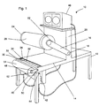
- FIG. 1 is a perspective view showing an embodiment of a printing plate mounting system of the present invention.
- FIG. 2 is a perspective view showing a printing plate mounting system of the present invention having a registration grid plate thereon.
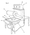
- FIG. 3 is a perspective view showing a printing plate mounting system of the present invention having a flexographic printing plate thereon.
- FIG. 4 is a side view showing a printing plate mounting system of the present invention having a flexographic printing plate thereon.
- FIG. 5 is an end view of a printing plate mounting system of the present invention.
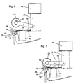
- FIG. 6 is a side view showing a printing plate mounting system of the present invention having a flexographic printing plate thereon showing a step in the operation of the system.
- FIG. 7 is a side view showing a printing plate mounting system of the present invention having a flexographic printing plate thereon showing another step in the operation of the system.
- FIG. 8 is a side view showing a printing plate mounting system of the present invention having a flexographic printing plate thereon showing yet another step in the operation of the system.
- FIG. 9 is a side view showing a printing plate mounting system of the present invention having a flexographic printing plate thereon showing still another step in the operation of the system.
- FIG. 10 is a side view showing the printing plate mounting system of the present invention having a flexographic printing plate thereon showing another step in the operation of the system.
- FIG. 11 is a side view showing the printing plate mounting system of the present invention having a flexographic printing plate thereon showing yet another step in the operation of the system.
- FIG. 12 is another perspective view showing the printing plate mounting system of the present invention.
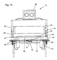
- FIG. 13 is an end view of another embodiment of a mounting device for use in the present invention.
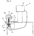
- FIG. 14 is a side view of another embodiment of a mounting device for use in the present invention.
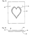
- FIG. 15 is a plan view of a flexograpic printing plate for use with the present invention.
- FIG. 16 is an end view of the flexograpic printing plate in FIG. 15.
- a printing plate mounting system is generally referred to by the numeral 10.
- the mounting device 10 depicted in FIGS. 1-14 includes legs 12, a printing plate support surface 14 connected to the legs 12, a pair of arms 16 removably hingedly connected at one end 18 to an extension 20 of the printing plate support surface 14.
- Rotatably removably connected at the other end 22 of the arms 16 is a plate cylinder 24 onto which a flexographic printing plate 26 (as seen in FIG. 3, for example) having a microdot thereon is to be mounted.
- the plate cylinder 24 will include a sticky-back 28 for affixing the printing plate 26 to the printing plate cylinder 26, but other means of accomplishing this will be apparent to those skilled in the art.
- One end 30 of the printing plate support surface 14 includes a transparent plate 32 which is disposed in a manner such that as the cylinder 24 is positioned adjacent the printing plate support surface 14, a central axis of the plate cylinder 24 will extend generally along a central axis 33 of the transparent plate 32.
- the central axis 33 is preferably marked in visible manner on the transparent plate 32 to aid in the registration of the printing plate 26 as later discussed herein.
- the transparent plate 32 is seated between recessed surfaced 34 and 36 of the printing plate support surface 14.
- the printing plate support surface may include a grid which is useful in registering the printing plate.
- the grid may be either integrally formed or formed as an overlay be laid over the printing plate support surface 14.
- a track 40 Extending beneath and movably connected to piece 36 of the printing plate support surface 14 adjacent the transparent plate 32 is a track 40.
- Reciprocally slidably lockably connected to the track 40 and actuatably positionable are cameras 42 which have their lens 44 predisposed to focus on the central axis 33 of the transparent plate 32 as each moves back and forth along the track 40.
- the cameras 42 are operably connected to a split screen monitor 46 which is, in this case, disposed on the extension 20 for ease of viewing while working, but may be disposed at any desired location.
- the track 40, cameras 42 and monitor screen 46 are of the type known to the art.
- the cameras 42 and monitor screen 46 are, for example, equipped to show 30 X magnification and have a centering circle to show the position and coordinates of the object viewed, i.e., a registration mark or microdot.
- a pair of arms 48 are pivotally mounted at one end 50 to the piece 34. At the arms' 48 other end 52 is a rotatably mounted pressure roller 54.
- the plate 26 may be formed from, for example, a photopolymer of the type from: Dupont Cyrel, B.A.S.F./NAPP Nylo-flex, Hercules pourable polymers, W.R. Grace Flexlite or Supratech Flexceed (trademarks); or a rubber of the type from: Uniroyal, Good-Year, B.F. Goodrich, Moss-type or Graphic-Arts Rubber. Such materials can typically be obtained in sizes up to approximately 150 cm x 300 cm..
- the flexographic printing plate 26 is produced in a conventional manner known to the art and as described in Flexography - Principles and Practices - Published by Flexographic Technical Association - Library of Congress Catalog Card No. 80-69506, Chapter VI, Engraving and Printing Plates, pages 149-183, incorporated herein by reference.
- the photopolymer is exposed to an ultraviolet light on one side for a predetermined period to harden and cure the photopolymer to a predetermined depth of a relief to be formed on the other side for the etching process.
- the other side of the plate is then covered with a photographic negative and exposed to the ultraviolet light to harden the printing surface through to the pre-hardened depth.
- the photographic negative is removed from the printing plate and the printing plate is washed with a polymer solvent to remove the unhardened material thus providing a printing surface 56, as seen in FIGS. 15 and 16.
- the plate 26 may be more fully hardened if desired.
- the photographic negative has been generated using the aid of a computer.
- This has enabled the formation of highly accurate graphic artwork.
- the artwork can be easily positioned at any desired x and y coordinates.
- This positioning ability precipitated the invention of microdots 58, as shown in FIGS. 15 and 16, for example, a pair of small dots formed in the plate 26, which have been widely used in the industry as a registering aid, i.e., a registration mark is created.
- microdots are uniformly formed along an x and/or y coordinate (via creating a small transparent circle in the photographic negative adjacent the art design) in the plate 26 and have been used principally in the registering process by attempting to align these microdots with a common x/y coordinate of another surface to permit the plate 26 to be mounted in register to a plate cylinder.
- Other registering configurations are contemplated in the present invention and are accordingly to be included within the scope of the present invention.
- the plate 26 is placed face down on the printing plate support surface 14 for mounting, as seen in FIG. 4.
- the microdots 58 are first positioned along the central axis 33 of the transparent plate 32 as seen in FIGS. 4 and 6.
- the cameras 42 are actuated along the track 40 to locate the microdots 58 substantially in the centering circle of the screen 46 and are then locked in position as depicted in FIG. 3 and 5.
- the plate cylinder 24 will vary up to several thousandths of an inch in diameter from one end to the other. Consequently, the printing plate 26 will have to be slightly canted to adjust for the variation in diameter size. This can be achieved by orienting the registration marks on opposite sides of the central axis 33, for example, and then adjusting the track 40 and cameras 42 to center the marks prior to fixing the cameras 42 for subsequent registration of other plates.
- the arms 16 are actuated to a point wherein the sticky-back 28 of the plate cylinder 24 is brought into contact with a back surface 60 of the plate 26.
- the arms 28 are then actuated in opposite direction such that the plate cylinder 24 is sufficiently disposed away from the printing plate support surface 14 with the printing plate 26 adhered thereto to permit the plate 26 to be rolled into position on the plate cylinder 24, as seen in FIG. 8.
- the arms 48 are actuated toward the the plate cylinder 24 to a point such that the pressure roller 54 is positioned against a front surface 62 as seen in FIGS. 9-11.
- the plate 26 is then rolled onto the sticky-back plate cylinder 24 in a uniform manner by virtue of the nip between the plate cylinder 24 and pressure roller 54 when one of the plate cylinder 24 and the pressure roller 54 is rotated.
- the arms 48 are then actuated in an opposite direction to remove the pressure roller 54 from the plate cylinder 24 as seen in FIG. 12.
- the plate cylinder 24 with the printing plate 26 thereon can then be removed from the arms 16 for use in a desired application.
- the mounting device 10 is employable for use in mounting varying size plate cylinders.
- the mounting device 10 in this embodiment differs in that it includes support members 64 fixedly connected in a predetermined alignment relationship to the support surface 14, bored surfaces 66, threaded shafts 68 and means 70 for reciprocating the threaded shafts 68.
- One of the shafts 68 extends through one of the bore surfaces 66 and has fixed to one end a bearing member 72 connected thereto which slidably fits between the support members 64.
- a plate cylinder 24 having a shaft 74 is disposed between the support members 64a and 64b such that the shaft 64 bears upon the bearing member 72.
- the shaft 74 is preferably of a diameter slightly less than the distance between support members 64a and 64b to keep the plate cylinder 24 in a predetermined alignment with respect to the transparent plate 32.
- the reciprocating means 70 includes a crank 76 and operably connected arms 78 and threaded wheels 80.
- the wheels 80 are operably connected to the threaded shafts 68 such that when the crank 76 is turned, the wheels 80 rotate to cause the shafts 68 to uniformly move between the support members 64 thus moving the plate cylinder 24 toward or away from the printing plate support surface 14 depending upon the direction in which the crank 76 is turned. It is recognized that other mechanisms may be employed to accomplish this result, such as a hydraulic mechanism.
- this embodiment provides an additional feature of being able to easily mount in register plates of varying sizes onto complimentary sized plate cylinders by virtue the shaft 74 remaining uniformly positioned and centered over the central axis 33 regardless of the plate cylinder 24 size.
Landscapes
- Printing Plates And Materials Therefor (AREA)
Applications Claiming Priority (2)
| Application Number | Priority Date | Filing Date | Title |
|---|---|---|---|
| US08/656,971 US5676058A (en) | 1996-06-06 | 1996-06-06 | Printing plate mounting system and method employing the same |
| US656971 | 1996-06-06 |
Publications (2)
| Publication Number | Publication Date |
|---|---|
| EP0811487A2 true EP0811487A2 (de) | 1997-12-10 |
| EP0811487A3 EP0811487A3 (de) | 1998-05-13 |
Family
ID=24635336
Family Applications (1)
| Application Number | Title | Priority Date | Filing Date |
|---|---|---|---|
| EP97850088A Withdrawn EP0811487A3 (de) | 1996-06-06 | 1997-06-06 | System zum Aufziehen von Druckplatten und Verfahren zu dessen Anwendung |
Country Status (2)
| Country | Link |
|---|---|
| US (1) | US5676058A (de) |
| EP (1) | EP0811487A3 (de) |
Cited By (4)
| Publication number | Priority date | Publication date | Assignee | Title |
|---|---|---|---|---|
| WO2007031842A1 (es) * | 2005-09-12 | 2007-03-22 | Nasini, Alfredo Carlos | Procedimiento para la fabricacion de rodillos para la impresion de materiales laminares, maquina para la realizacion del procedimiento y soporte de impresion para los rodillos de impresion |
| NL2005383C2 (nl) * | 2010-09-22 | 2012-03-26 | Av Flexologic Bv | Inrichting en werkwijze voor het positioneren van een drukplaat op een drager. |
| EP2397327A3 (de) * | 2010-06-18 | 2015-08-12 | Esko-Graphics Imaging GmbH | Nichtdruckende Registrierungsmarkierungen auf einer Druckplatte |
| CN105730002A (zh) * | 2016-04-13 | 2016-07-06 | 龙会伦 | 一种柔版自动贴版装置 |
Families Citing this family (26)
| Publication number | Priority date | Publication date | Assignee | Title |
|---|---|---|---|---|
| IT1293502B1 (it) * | 1997-07-29 | 1999-03-01 | Gabriella Cacchi | Procedimento di montaggio di cliche' su maniche e relativo montaggio delle maniche su rulli di macchine da stampa flessografiche |
| US6117615A (en) * | 1999-07-28 | 2000-09-12 | E. I. Du Pont De Nemours And Company | Method for mounting multiple printing elements onto a cylindrical element |
| US6298783B1 (en) * | 1999-10-29 | 2001-10-09 | Fargo Electronics, Inc. | Printhead alignment device and method of use |
| US6688364B2 (en) | 2001-03-22 | 2004-02-10 | Robert C. Simpson | Sign applique transfer and assembly apparatus |
| DE10345290B4 (de) * | 2003-09-30 | 2013-09-26 | Leuze Electronic Gmbh & Co. Kg | Vorrichtung zur Erfassung von Passermarken in einer Druckmaschine |
| ITBO20040749A1 (it) * | 2004-12-02 | 2005-03-02 | Bieffebi Spa | Macchina per il montaggio a registro di cliche' flessografici con sistema informatico virtuale |
| JP2008528315A (ja) * | 2005-01-21 | 2008-07-31 | エム・アー・エヌ・ローラント・ドルックマシーネン・アクチエンゲゼルシャフト | 印刷装置内の、雌型と雄型とを備えたエンボス・ツール |
| WO2007047619A2 (en) * | 2005-10-17 | 2007-04-26 | Gartner Gerry J | System and method for mounting a plate to an adhesive member |
| US20070125654A1 (en) * | 2005-12-02 | 2007-06-07 | Buckley Paul W | Electroform, methods of making electroforms, and products made from electroforms |
| US20070126144A1 (en) * | 2005-12-02 | 2007-06-07 | Yadong Jin | Polish/texture thermoplastic film and method for making the same |
| US20070126148A1 (en) * | 2005-12-02 | 2007-06-07 | General Electric Company | Microstructured embossing drum and articles made therefrom |
| US20070125652A1 (en) * | 2005-12-02 | 2007-06-07 | Buckley Paul W | Electroform, methods of making electroforms, and products made from electroforms |
| US20070125655A1 (en) * | 2005-12-02 | 2007-06-07 | Buckley Paul W | Electroform, methods of making electroforms, and products made from electroforms |
| US20070125248A1 (en) * | 2005-12-02 | 2007-06-07 | Coyle Dennis J | Embossing drum system with removable outer sleeve and methods of use |
| US20070125653A1 (en) * | 2005-12-02 | 2007-06-07 | Coyle Dennis J | Multilayer electroform, methods of making multilayer electroforms, and products made therefrom |
| US20070125651A1 (en) * | 2005-12-02 | 2007-06-07 | Buckley Paul W | Electroform, methods of making electroforms, and products made from electroforms |
| US8534194B2 (en) * | 2006-10-23 | 2013-09-17 | Bobst Bielefeld Gmbh | Rotary printing press and method for adjusting a cylinder thereof |
| EP2089227A2 (de) * | 2006-10-23 | 2009-08-19 | Fischer & Krecke GmbH | Rotationsdruckmaschine und verfahren zum einstellen einer walze derselben |
| DE602006012688D1 (de) † | 2006-10-23 | 2010-04-15 | Fischer & Krecke Gmbh | Verfahren, Monatagevorrichtung und Steuereinheit zur Justierung einer Walze in einer Druckmaschine |
| JP5306049B2 (ja) * | 2009-05-11 | 2013-10-02 | 株式会社光文堂 | 版貼装置及び版貼装置の版貼方法 |
| GB201106348D0 (en) * | 2011-04-14 | 2011-06-01 | J M Heaford Ltd | Flexographic plate mounting apparatus |
| KR101967015B1 (ko) * | 2011-09-16 | 2019-04-08 | 쓰리엠 이노베이티브 프로퍼티즈 캄파니 | 미세-접촉 인쇄용 스탬프를 스탬핑 롤에 장착하기 위한 방법 및 장치 |
| US20140230674A1 (en) * | 2013-02-20 | 2014-08-21 | Kurt M. Sanger | System for mounting a flexographic printing plate |
| GB2533020B (en) | 2015-08-25 | 2020-12-09 | Jm Heaford Ltd | Apparatus and method for mounting a flexible plate |
| EP4000932A1 (de) * | 2020-11-19 | 2022-05-25 | Bobst Bielefeld GmbH | Verfahren und vorrichtung zum befestigen einer druckplatte auf einem druckzylinder |
| NL2032173B1 (en) * | 2022-06-15 | 2023-12-21 | Av Flexologic Bv | Mounting device for a computer-assisted mounting of a flexible printing plate on a cylindrical carrier, and method of a computer-assisted mounting a flexible printing plate on a cylindrical carrier. |
Family Cites Families (14)
| Publication number | Priority date | Publication date | Assignee | Title |
|---|---|---|---|---|
| US3616055A (en) * | 1969-05-16 | 1971-10-26 | David H Mages | Optical plate mounter |
| US3605622A (en) * | 1969-07-14 | 1971-09-20 | Ibraham E R Zarip | Alighment method for plate and offset duplication processes |
| US4449452A (en) * | 1982-05-28 | 1984-05-22 | Rapid Packaging Services Pty. Ltd. | Rapid plate mounter |
| US4653369A (en) * | 1984-07-09 | 1987-03-31 | Menasha Corporation | Flexographic printing plate mounting method and apparatus |
| US4611539A (en) * | 1985-09-30 | 1986-09-16 | Carl Ireton | Device and method for the precision mounting of flexible printing plates |
| US4705590A (en) * | 1986-11-12 | 1987-11-10 | Edward Vandenberg | Machine for adhesively mounting a printing plate on a plate roll |
| DK171290B1 (da) * | 1987-02-27 | 1996-08-26 | Du Pont | Apparat til montering af en bøjelig kliche på en formatcylinder til en trykmaskine |
| US5065677A (en) * | 1989-12-27 | 1991-11-19 | Leader Engineering Fabrication Inc. | Printing plate mounting and proofing apparatus |
| JP3030573B2 (ja) * | 1991-05-30 | 2000-04-10 | 株式会社小森コーポレーション | 版胴への刷版装着装置 |
| DE4132088C1 (en) * | 1991-09-23 | 1992-10-15 | Johannes Klagenfurt Kaernten At Zimmer | Mfg. precisely fitting, cylindrical printing stencil - fits end rings to stencil cylinder without notches, providing latter only after adhesive hardening |
| DE69312811T2 (de) * | 1992-05-18 | 1998-03-19 | Riso Kagaku Corp | Kartendruckverfahren, Vorrichtung zur Aufrechterhaltung der Position von Originalen und Papier für Kartendruck |
| GB2281250B (en) * | 1993-08-28 | 1997-10-08 | Flexographic Services Limited | A method of mounting a printing plate on a mounting sheet |
| US5488781A (en) * | 1994-12-13 | 1996-02-06 | Av Flexologic B.V. | Positioning apparatus for printing plates |
| CA2252500C (en) * | 1996-04-22 | 2004-07-06 | Leader Engineering-Fabrication, Inc. | Printing plate mounting structure |
-
1996
- 1996-06-06 US US08/656,971 patent/US5676058A/en not_active Expired - Fee Related
-
1997
- 1997-06-06 EP EP97850088A patent/EP0811487A3/de not_active Withdrawn
Cited By (6)
| Publication number | Priority date | Publication date | Assignee | Title |
|---|---|---|---|---|
| WO2007031842A1 (es) * | 2005-09-12 | 2007-03-22 | Nasini, Alfredo Carlos | Procedimiento para la fabricacion de rodillos para la impresion de materiales laminares, maquina para la realizacion del procedimiento y soporte de impresion para los rodillos de impresion |
| EP2397327A3 (de) * | 2010-06-18 | 2015-08-12 | Esko-Graphics Imaging GmbH | Nichtdruckende Registrierungsmarkierungen auf einer Druckplatte |
| NL2005383C2 (nl) * | 2010-09-22 | 2012-03-26 | Av Flexologic Bv | Inrichting en werkwijze voor het positioneren van een drukplaat op een drager. |
| WO2012039603A1 (en) * | 2010-09-22 | 2012-03-29 | Av Flexologic Bv | Method and device for removably positioning a printing plate on a carrier |
| CN105730002A (zh) * | 2016-04-13 | 2016-07-06 | 龙会伦 | 一种柔版自动贴版装置 |
| CN105730002B (zh) * | 2016-04-13 | 2019-02-05 | 上悦(上海)印刷有限公司 | 一种柔版自动贴版装置 |
Also Published As
| Publication number | Publication date |
|---|---|
| US5676058A (en) | 1997-10-14 |
| EP0811487A3 (de) | 1998-05-13 |
Similar Documents
| Publication | Publication Date | Title |
|---|---|---|
| US5676058A (en) | Printing plate mounting system and method employing the same | |
| EP0773105B1 (de) | System zum Aufziehen von Druckplatten, Aufzeichnungsplatte des physischen Registers und Verfahren zu deren Verwendung | |
| US6823793B2 (en) | Method and apparatus for mounting flexographic plate segments | |
| US4380956A (en) | Mounting of flexible printing plates | |
| US5850789A (en) | Method and apparatus for mounting printing plates | |
| AU658899B2 (en) | Direct-to-press imaging system for use in lithopraphic printing | |
| US4449452A (en) | Rapid plate mounter | |
| US6058839A (en) | Computerized cutting method and apparatus for use in printing operations | |
| US7171901B2 (en) | Flexographic printing method | |
| US20120210895A1 (en) | Method for performing print job | |
| CA2268624A1 (en) | Method and apparatus for use in offset printing | |
| JP2756499B2 (ja) | 印刷版及び凸版印刷方法 | |
| US4860650A (en) | Method for attaining longitudinal registry of rolls in printing presses | |
| US7033450B2 (en) | Flexographic printing method | |
| CN101321625B (zh) | 将印版安装至粘接构件的系统和方法 | |
| GB2083411A (en) | Improvements in or relating to the mounting of flexible printing plates | |
| US4846059A (en) | Film registration table for flexible printing plates | |
| US4750248A (en) | Film and plate registration system | |
| US5578364A (en) | Gravure plate assembly | |
| US4846063A (en) | Film and plate registration system for flexographic printing | |
| EP1072958B1 (de) | Verfahren zur Befestigung von mehreren Druckelementen auf einem zylindrischen Element | |
| EP1007362B1 (de) | Verfahren zum montieren von druckplatten auf hülsen und zum montieren der so hergestellten hülsen auf zylinder einer flexographischen maschine | |
| CA1302061C (en) | Film and plate registration system for flexographic printing process | |
| JP2513092Y2 (ja) | 位置決め対象物の精密位置決め機構 | |
| JP3072935B2 (ja) | 見当プリセット方法 |
Legal Events
| Date | Code | Title | Description |
|---|---|---|---|
| PUAI | Public reference made under article 153(3) epc to a published international application that has entered the european phase |
Free format text: ORIGINAL CODE: 0009012 |
|
| AK | Designated contracting states |
Kind code of ref document: A2 Designated state(s): AT CH DE DK ES FR GB IT LI PT SE |
|
| PUAL | Search report despatched |
Free format text: ORIGINAL CODE: 0009013 |
|
| AK | Designated contracting states |
Kind code of ref document: A3 Designated state(s): AT BE CH DE DK ES FI FR GB GR IE IT LI LU MC NL PT SE |
|
| 17P | Request for examination filed |
Effective date: 19981111 |
|
| AKX | Designation fees paid |
Free format text: AT BE CH DE DK ES FI FR GB GR LI |
|
| RBV | Designated contracting states (corrected) |
Designated state(s): AT BE CH DE DK ES FI FR GB GR LI |
|
| RBV | Designated contracting states (corrected) |
Designated state(s): AT CH DE DK ES FR GB IT LI PT SE |
|
| 17Q | First examination report despatched |
Effective date: 19990531 |
|
| RIC1 | Information provided on ipc code assigned before grant |
Free format text: 7B 41F 27/12 A, 7B 41F 33/00 B, 7B 41F 27/00 B, 7G 03F 9/00 B |
|
| GRAG | Despatch of communication of intention to grant |
Free format text: ORIGINAL CODE: EPIDOS AGRA |
|
| RIC1 | Information provided on ipc code assigned before grant |
Free format text: 7B 41F 27/12 A, 7B 41F 33/00 B, 7B 41F 27/00 B, 7G 03F 9/00 B |
|
| STAA | Information on the status of an ep patent application or granted ep patent |
Free format text: STATUS: THE APPLICATION IS DEEMED TO BE WITHDRAWN |
|
| 18D | Application deemed to be withdrawn |
Effective date: 20010102 |