EP0811531B1 - Airbagmodul mit Hupenschalter - Google Patents
Airbagmodul mit Hupenschalter Download PDFInfo
- Publication number
- EP0811531B1 EP0811531B1 EP97108668A EP97108668A EP0811531B1 EP 0811531 B1 EP0811531 B1 EP 0811531B1 EP 97108668 A EP97108668 A EP 97108668A EP 97108668 A EP97108668 A EP 97108668A EP 0811531 B1 EP0811531 B1 EP 0811531B1
- Authority
- EP
- European Patent Office
- Prior art keywords
- airbag
- airbag module
- supporting body
- wall
- supporting
- Prior art date
- Legal status (The legal status is an assumption and is not a legal conclusion. Google has not performed a legal analysis and makes no representation as to the accuracy of the status listed.)
- Expired - Lifetime
Links
- 239000010410 layer Substances 0.000 description 5
- 239000011888 foil Substances 0.000 description 3
- 239000002356 single layer Substances 0.000 description 3
- 239000006260 foam Substances 0.000 description 2
- 239000013013 elastic material Substances 0.000 description 1
- 238000005265 energy consumption Methods 0.000 description 1
- 230000003116 impacting effect Effects 0.000 description 1
- 239000000463 material Substances 0.000 description 1
- 239000002184 metal Substances 0.000 description 1
- 239000002905 metal composite material Substances 0.000 description 1
- 238000012856 packing Methods 0.000 description 1
- 230000000087 stabilizing effect Effects 0.000 description 1
- 229920003002 synthetic resin Polymers 0.000 description 1
- 239000000057 synthetic resin Substances 0.000 description 1
- 210000002105 tongue Anatomy 0.000 description 1
Images
Classifications
-
- B—PERFORMING OPERATIONS; TRANSPORTING
- B60—VEHICLES IN GENERAL
- B60Q—ARRANGEMENT OF SIGNALLING OR LIGHTING DEVICES, THE MOUNTING OR SUPPORTING THEREOF OR CIRCUITS THEREFOR, FOR VEHICLES IN GENERAL
- B60Q5/00—Arrangement or adaptation of acoustic signal devices
- B60Q5/001—Switches therefor
- B60Q5/003—Switches therefor mounted on the steering wheel
-
- B—PERFORMING OPERATIONS; TRANSPORTING
- B60—VEHICLES IN GENERAL
- B60R—VEHICLES, VEHICLE FITTINGS, OR VEHICLE PARTS, NOT OTHERWISE PROVIDED FOR
- B60R21/00—Arrangements or fittings on vehicles for protecting or preventing injuries to occupants or pedestrians in case of accidents or other traffic risks
- B60R21/02—Occupant safety arrangements or fittings, e.g. crash pads
- B60R21/04—Padded linings for the vehicle interior ; Energy absorbing structures associated with padded or non-padded linings
- B60R21/05—Padded linings for the vehicle interior ; Energy absorbing structures associated with padded or non-padded linings associated with the steering wheel, steering hand lever or steering column
-
- B—PERFORMING OPERATIONS; TRANSPORTING
- B60—VEHICLES IN GENERAL
- B60R—VEHICLES, VEHICLE FITTINGS, OR VEHICLE PARTS, NOT OTHERWISE PROVIDED FOR
- B60R21/00—Arrangements or fittings on vehicles for protecting or preventing injuries to occupants or pedestrians in case of accidents or other traffic risks
- B60R21/02—Occupant safety arrangements or fittings, e.g. crash pads
- B60R21/16—Inflatable occupant restraints or confinements designed to inflate upon impact or impending impact, e.g. air bags
- B60R21/20—Arrangements for storing inflatable members in their non-use or deflated condition; Arrangement or mounting of air bag modules or components
- B60R21/215—Arrangements for storing inflatable members in their non-use or deflated condition; Arrangement or mounting of air bag modules or components characterised by the covers for the inflatable member
- B60R21/2165—Arrangements for storing inflatable members in their non-use or deflated condition; Arrangement or mounting of air bag modules or components characterised by the covers for the inflatable member characterised by a tear line for defining a deployment opening
- B60R21/21656—Steering wheel covers or similar cup-shaped covers
- B60R21/21658—Steering wheel covers or similar cup-shaped covers with integrated switches, e.g. horn switches
-
- B—PERFORMING OPERATIONS; TRANSPORTING
- B60—VEHICLES IN GENERAL
- B60R—VEHICLES, VEHICLE FITTINGS, OR VEHICLE PARTS, NOT OTHERWISE PROVIDED FOR
- B60R21/00—Arrangements or fittings on vehicles for protecting or preventing injuries to occupants or pedestrians in case of accidents or other traffic risks
- B60R21/02—Occupant safety arrangements or fittings, e.g. crash pads
- B60R21/16—Inflatable occupant restraints or confinements designed to inflate upon impact or impending impact, e.g. air bags
- B60R21/20—Arrangements for storing inflatable members in their non-use or deflated condition; Arrangement or mounting of air bag modules or components
- B60R21/217—Inflation fluid source retainers, e.g. reaction canisters; Connection of bags, covers, diffusers or inflation fluid sources therewith or together
Definitions
- the invention relates to a steering wheel of a motor vehicle airbag module can be arranged with a horn switch, which is designed as a pressure-sensitive switching film.
- An airbag device with a pressure-sensitive horn switch is known from DE 43 10 625.
- the horn switch is part of a cushion arrangement, consisting of a top layer of a elastic synthetic resin, a stiff insert, which in the Side wall of the pillow is embedded, one made of sheet metal composite switch, the metal sheets have a stabilizing shape and on the stiff Insert are supported.
- the contact blades of the horn switch lie between the elastic cover layer and the package of the folded airbag, which in turn is on the Diffuser of the gas generator rests.
- the amount of the package of the folded airbag can not in series production be produced uniformly. Rather, it must be with one considerable tolerance for the height of this package become.
- the object of the invention is a generic on the steering wheel of a motor vehicle Airbag module can be arranged with a horn switch to create the as a pressure sensitive switching foil is formed and in which the actuation path and Switching force regardless of the packing tolerance of the airbag is constant.
- the thickness of the airbag material is clearly determined and can be closely tolerated in relation to a location the switching path for actuating the horn switch exactly and repeatable within a series.
- the Horn switch can thus easily by a Switching film are formed with a defined pressure and responsive to short shift travel.
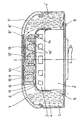
- a gas generator is in a housing 1 of the airbag module 2 attached, a cap-shaped at its top Diffuser 3 carries. Annular around the gas generator 2 and a folded airbag 4 is arranged on the diffuser 3, the one with its edge 5 in a manner known per se on the ground the housing 1 is attached. A single layer 6 of the Airbag 4 forms the bottom and extends over the gas generator 2 and thus across the diffuser 3.
- a cap 7 with an elastic wall 8 covers the airbag module down to the vehicle interior.
- a pressure-sensitive switching film 9 is stored and by means of electrical lines, not shown connected to a voltage source as well as a horn so that closed a contact when pressure on the switching film 9 and current from the voltage source to the Horn flows.
- the one shown in the drawing to the left of the center line Execution are at the bottom of the elastic Wall 8 of the cap 7 supporting ribs 10 attached, the extend close to the boundary of the diffuser 3. Between the ends of the support ribs 10 and the Diffuser 3 is the bottom of the airbag 4 forming single layer 6.
- the upper cover of the diffuser 3 acts thus as a support body 11 on which an external Pressure on the outer side of the elastic wall 8, namely when the horn is actuated, the inner side over the Supporting ribs 10 supports.
- the individual layer 6 of the airbag 4 between the support ribs 10 and the support body 11 falsifies the specified switching path of the horn switch Not.
- the space between the support ribs 10 is with a foam 12 filled so that at one Head impact on the wall 8 in the event of a crash the required Energy consumption is guaranteed.
- a second embodiment of the invention is in the Drawing shown to the right of the center line, matching Parts with the same reference numerals as for the previously described embodiment are provided.
- the bottom of the gas bag 4 ' is direct as a single layer 6' passed under the elastic wall 8 'of the cap 7'.
- a rib body 13 Between the position 6 'and that of the diffuser 3 formed support body 11 is a rib body 13, which is fastened to the supporting body 3 with resilient hooks 14 is.
- the rib body 13 has support ribs 10 'which are supported on the support body 11.
- the gap between the support ribs 10 ' is with a foam 12 'filled, the one together with the support ribs 10' Head impact on the airbag module dampens.
- Such Type can be compared to the type described first then have advantages if the hardness of the support ribs out the elastic material of the wall 8 is not sufficient to the kinetic energy of an impacting body part by absorbing deformation energy.
Landscapes
- Engineering & Computer Science (AREA)
- Mechanical Engineering (AREA)
- Physics & Mathematics (AREA)
- Acoustics & Sound (AREA)
- Air Bags (AREA)
Description
Claims (4)
- Am Lenkrad eines Kraftfahrzeuges anordenbarer Airbagmodul mit einem als druckempfindliche Schaltfolie (9) ausgebildeten Hupenschalter, wobei die Schaltfolie (9) in einer zum Fahrzeuginnenraum weisenden elastischen Wand (8, 8') einer den Airbagmodul abdeckenden Kappe (7) eingelagert ist, die Wand (8, 8') von einem Stützkörper (11) beabstandet ist und ein Luftsack (4, 4') mit nur einer Lage (6, 6') zwischen der Wand (8, 8') und dem Stützkörper (11) liegt, dadurch gekennzeichnet, daß entweder an der Unterseite der elastischen Wand (8) als deren Bestandteil Stützrippen (10) angebracht sind die sich bis nahe an den Stützkörper (11) erstrecken und die eine Lage (6) des Luftsackes (4) zwischen den Stützrippen (10) und dem Stützkörper (11) angeordnet ist, oder daß ein Rippenkörper (13) mit Stützrippen (10') vorgesehen ist, der auf dem Stützkörper (11) aufliegt und die eine Lage (6') des Luftsackes (4') zwischen dem Rippenkörper (13) und der elastischen Wand (8') angeordnet ist.
- Airbagmodul nach Anspruch 1, dadurch gekennzeichnet, daß der Rippenkörper (13) mit dem Stützkörper (11) verbunden ist.
- Airbagmodul nach Anspruch 1 oder 2, dadurch gekennzeichnet, daß der Stützkörper (11) von einem Diffusor (3) eines Gasgenerators (2) gebildet ist.
- Airbagmodul nach zumindest einem der Ansprüche 1 bis 3, dadurch gekennzeichnet, daß der Luftsack (4, 4') ringförmig um den Stützkörper (11) gefaltet angeordnet und mit seinem Rand (5) am Gehäuse (1) des Airbagmoduls befestigt ist sowie mit der einen Lage (6, 6') den Stützkörper (11) überspannt.
Applications Claiming Priority (2)
| Application Number | Priority Date | Filing Date | Title |
|---|---|---|---|
| DE19622863 | 1996-06-07 | ||
| DE19622863A DE19622863A1 (de) | 1996-06-07 | 1996-06-07 | Airbagmodul mit Hupenschalter |
Publications (3)
| Publication Number | Publication Date |
|---|---|
| EP0811531A2 EP0811531A2 (de) | 1997-12-10 |
| EP0811531A3 EP0811531A3 (de) | 2000-01-12 |
| EP0811531B1 true EP0811531B1 (de) | 2003-07-30 |
Family
ID=7796375
Family Applications (1)
| Application Number | Title | Priority Date | Filing Date |
|---|---|---|---|
| EP97108668A Expired - Lifetime EP0811531B1 (de) | 1996-06-07 | 1997-05-30 | Airbagmodul mit Hupenschalter |
Country Status (2)
| Country | Link |
|---|---|
| EP (1) | EP0811531B1 (de) |
| DE (2) | DE19622863A1 (de) |
Families Citing this family (4)
| Publication number | Priority date | Publication date | Assignee | Title |
|---|---|---|---|---|
| DE29813240U1 (de) * | 1998-07-24 | 1998-10-01 | TRW Automotive Safety Systems GmbH, 63743 Aschaffenburg | Airbagmodul mit Hupenfolie |
| DE10020929C5 (de) * | 2000-04-28 | 2006-07-13 | Key Safety Systems, Inc.(n.d.Ges.d.Staates Delaware), Sterling Heights | Airbagmodul |
| DE102023113883A1 (de) * | 2023-05-26 | 2024-11-28 | ZF Automotive Safety Germany GmbH | Hupenmodul, verfahren zur herstellung eines hupenmoduls und lenkrad mit einem hupenmodul |
| DE102023113882A1 (de) * | 2023-05-26 | 2024-11-28 | ZF Automotive Safety Germany GmbH | Hupenmodul und lenkrad mit einem hupenmodul |
Family Cites Families (10)
| Publication number | Priority date | Publication date | Assignee | Title |
|---|---|---|---|---|
| US3525536A (en) * | 1968-10-11 | 1970-08-25 | Eaton Yale & Towne | Vehicle safety apparatus positioned on steering wheel |
| US3819205A (en) * | 1972-09-25 | 1974-06-25 | Gen Motors Corp | Modular occupant restraint system |
| US4903986A (en) * | 1988-11-14 | 1990-02-27 | General Motors Corporation | Modular occupant restraint system |
| DE4034539A1 (de) * | 1989-10-30 | 1991-05-02 | Toyoda Gosei Kk | Lenkrad mit luftsackvorrichtung |
| US5423569A (en) * | 1991-07-08 | 1995-06-13 | United Technologies Automotive, Inc. | Electric signalling in a supplemental passenger restraint system |
| JP3123166B2 (ja) * | 1991-12-17 | 2001-01-09 | タカタ株式会社 | エアバッグ装置のモジュールカバー |
| US5269559A (en) * | 1992-04-29 | 1993-12-14 | Davidson Textron Inc. | Horn actuator incorporating a transducer in a steering wheel |
| US5265905A (en) * | 1993-01-07 | 1993-11-30 | Ford Motor Company | Air bag cover horn blow switch assembly |
| WO1995020233A1 (en) * | 1994-01-21 | 1995-07-27 | Davidson Textron Inc. | A horn actuator incorporating a transducer in a steering wheel |
| DE29606322U1 (de) * | 1996-03-26 | 1996-06-20 | Petri Ag, 63743 Aschaffenburg | Airbagabdeckung mit Hupenfolien |
-
1996
- 1996-06-07 DE DE19622863A patent/DE19622863A1/de not_active Ceased
-
1997
- 1997-05-30 DE DE59710491T patent/DE59710491D1/de not_active Expired - Lifetime
- 1997-05-30 EP EP97108668A patent/EP0811531B1/de not_active Expired - Lifetime
Also Published As
| Publication number | Publication date |
|---|---|
| DE59710491D1 (de) | 2003-09-04 |
| DE19622863A1 (de) | 1997-12-11 |
| EP0811531A2 (de) | 1997-12-10 |
| EP0811531A3 (de) | 2000-01-12 |
Similar Documents
| Publication | Publication Date | Title |
|---|---|---|
| DE69204247T2 (de) | In der Lenkradabdeckung integrierter Hupenschalter mit verstärkender fester Struktur. | |
| DE3011463C2 (de) | ||
| EP1216893B1 (de) | Fahrzeuglenkrad | |
| DE19911082B4 (de) | Vorrichtung für eine aufblasbare Fahrzeuginsassenschutzvorrichtung | |
| DE60010878T2 (de) | Airbag-abdeckung mit fahrerpositionssensor und hupenschalter | |
| DE4034539C2 (de) | ||
| DE4141908A1 (de) | Iniator- oder zuendanordnung fuer eine airbagaufblasvorrichtung | |
| EP0834442A2 (de) | Verschlusselement aus Kunststoff | |
| DE69728455T2 (de) | Luftsackanordnung mit Hupenschaltertasche | |
| DE19539164A1 (de) | Fahrzeugsicherheitsvorrichtung mit aufblasbaren Rückhaltemitteln | |
| DE19617758C1 (de) | Abdeckung für ein Gassackmodul | |
| DE19736488A1 (de) | Fahrzeuginsassenschutzvorrichtung | |
| DE69514626T2 (de) | Entfaltungsdeckel zum Gebrauch in einer Fahrzeuginsassen-Rückhaltevorrichtung | |
| DE60132715T2 (de) | Airbag-modul mit hupenschalter | |
| EP0811531A2 (de) | Airbagmodul mit Hupenschalter | |
| EP2419305B1 (de) | Gassackanordnung für ein fahrzeuginsassen-rückhaltesystem und verfahren zum herstellen einer gassackanordnung | |
| DE19732022A1 (de) | Gassackeinrichtung mit integriertem Hupenschalter | |
| EP1238866B1 (de) | Gassack-Modul | |
| DE60201545T2 (de) | Fahrerseitiges Luftsackmodul | |
| DE19809225A1 (de) | Hupschalter für ein Airbagmodul | |
| DE19633696B4 (de) | Airbagabdeckklappe | |
| EP0968104B1 (de) | Anordnung zur hupbetätigung bei modulintegrierten lenkrädern | |
| DE19809228A1 (de) | Hupschalter für ein Airbagmodul | |
| DE102016213693A1 (de) | Gasgeneratoranordnung für ein Fahrzeuginsassen-Rückhaltesystem | |
| DE10349537A1 (de) | Lenkrad für ein Kraftfahrzeug |
Legal Events
| Date | Code | Title | Description |
|---|---|---|---|
| PUAI | Public reference made under article 153(3) epc to a published international application that has entered the european phase |
Free format text: ORIGINAL CODE: 0009012 |
|
| AK | Designated contracting states |
Kind code of ref document: A2 Designated state(s): DE FR GB IT |
|
| PUAL | Search report despatched |
Free format text: ORIGINAL CODE: 0009013 |
|
| AK | Designated contracting states |
Kind code of ref document: A3 Designated state(s): DE FR GB IT |
|
| 17P | Request for examination filed |
Effective date: 20000603 |
|
| GRAH | Despatch of communication of intention to grant a patent |
Free format text: ORIGINAL CODE: EPIDOS IGRA |
|
| GRAH | Despatch of communication of intention to grant a patent |
Free format text: ORIGINAL CODE: EPIDOS IGRA |
|
| GRAA | (expected) grant |
Free format text: ORIGINAL CODE: 0009210 |
|
| AK | Designated contracting states |
Designated state(s): DE FR GB IT |
|
| REG | Reference to a national code |
Ref country code: GB Ref legal event code: FG4D Free format text: NOT ENGLISH |
|
| REF | Corresponds to: |
Ref document number: 59710491 Country of ref document: DE Date of ref document: 20030904 Kind code of ref document: P |
|
| GBT | Gb: translation of ep patent filed (gb section 77(6)(a)/1977) |
Effective date: 20031023 |
|
| ET | Fr: translation filed | ||
| PLBE | No opposition filed within time limit |
Free format text: ORIGINAL CODE: 0009261 |
|
| STAA | Information on the status of an ep patent application or granted ep patent |
Free format text: STATUS: NO OPPOSITION FILED WITHIN TIME LIMIT |
|
| 26N | No opposition filed |
Effective date: 20040504 |
|
| REG | Reference to a national code |
Ref country code: GB Ref legal event code: 732E Free format text: REGISTERED BETWEEN 20090219 AND 20090225 |
|
| REG | Reference to a national code |
Ref country code: GB Ref legal event code: 732E Free format text: REGISTERED BETWEEN 20090305 AND 20090311 |
|
| REG | Reference to a national code |
Ref country code: GB Ref legal event code: 732E Free format text: REGISTERED BETWEEN 20091029 AND 20091104 |
|
| REG | Reference to a national code |
Ref country code: GB Ref legal event code: 732E Free format text: REGISTERED BETWEEN 20091105 AND 20091111 |
|
| REG | Reference to a national code |
Ref country code: DE Ref legal event code: R081 Ref document number: 59710491 Country of ref document: DE Owner name: GM GLOBAL TECHNOLOGY OPERATIONS LLC (N. D. GES, US Free format text: FORMER OWNER: GM GLOBAL TECHNOLOGY OPERATIONS, INC., DETROIT, MICH., US Effective date: 20110323 Ref country code: DE Ref legal event code: R081 Ref document number: 59710491 Country of ref document: DE Owner name: GM GLOBAL TECHNOLOGY OPERATIONS LLC (N. D. GES, US Free format text: FORMER OWNER: GM GLOBAL TECHNOLOGY OPERATIONS, INC., DETROIT, US Effective date: 20110323 |
|
| PGFP | Annual fee paid to national office [announced via postgrant information from national office to epo] |
Ref country code: FR Payment date: 20110523 Year of fee payment: 15 |
|
| PGFP | Annual fee paid to national office [announced via postgrant information from national office to epo] |
Ref country code: GB Payment date: 20110525 Year of fee payment: 15 |
|
| PGFP | Annual fee paid to national office [announced via postgrant information from national office to epo] |
Ref country code: DE Payment date: 20110525 Year of fee payment: 15 Ref country code: IT Payment date: 20110523 Year of fee payment: 15 |
|
| GBPC | Gb: european patent ceased through non-payment of renewal fee |
Effective date: 20120530 |
|
| PG25 | Lapsed in a contracting state [announced via postgrant information from national office to epo] |
Ref country code: IT Free format text: LAPSE BECAUSE OF NON-PAYMENT OF DUE FEES Effective date: 20120530 |
|
| REG | Reference to a national code |
Ref country code: FR Ref legal event code: ST Effective date: 20130131 |
|
| REG | Reference to a national code |
Ref country code: DE Ref legal event code: R119 Ref document number: 59710491 Country of ref document: DE Effective date: 20121201 |
|
| PG25 | Lapsed in a contracting state [announced via postgrant information from national office to epo] |
Ref country code: GB Free format text: LAPSE BECAUSE OF NON-PAYMENT OF DUE FEES Effective date: 20120530 Ref country code: FR Free format text: LAPSE BECAUSE OF NON-PAYMENT OF DUE FEES Effective date: 20120531 |
|
| PG25 | Lapsed in a contracting state [announced via postgrant information from national office to epo] |
Ref country code: DE Free format text: LAPSE BECAUSE OF NON-PAYMENT OF DUE FEES Effective date: 20121201 |