EP0811736B1 - Armierung von Mauerwerk - Google Patents
Armierung von Mauerwerk Download PDFInfo
- Publication number
- EP0811736B1 EP0811736B1 EP97303835A EP97303835A EP0811736B1 EP 0811736 B1 EP0811736 B1 EP 0811736B1 EP 97303835 A EP97303835 A EP 97303835A EP 97303835 A EP97303835 A EP 97303835A EP 0811736 B1 EP0811736 B1 EP 0811736B1
- Authority
- EP
- European Patent Office
- Prior art keywords
- reinforcement
- central core
- groove
- projections
- masonry
- Prior art date
- Legal status (The legal status is an assumption and is not a legal conclusion. Google has not performed a legal analysis and makes no representation as to the accuracy of the status listed.)
- Expired - Lifetime
Links
- 230000002787 reinforcement Effects 0.000 title claims abstract description 79
- 125000006850 spacer group Chemical group 0.000 claims abstract description 24
- 239000000463 material Substances 0.000 claims abstract description 19
- 238000000034 method Methods 0.000 claims description 13
- 238000003780 insertion Methods 0.000 claims description 6
- 230000037431 insertion Effects 0.000 claims description 6
- 230000003014 reinforcing effect Effects 0.000 claims description 5
- 229910001220 stainless steel Inorganic materials 0.000 claims description 5
- 239000010935 stainless steel Substances 0.000 claims description 3
- 229910000831 Steel Inorganic materials 0.000 description 2
- 238000013461 design Methods 0.000 description 2
- 239000004570 mortar (masonry) Substances 0.000 description 2
- 239000007787 solid Substances 0.000 description 2
- 239000010959 steel Substances 0.000 description 2
- 239000007767 bonding agent Substances 0.000 description 1
- 239000002131 composite material Substances 0.000 description 1
- 230000006835 compression Effects 0.000 description 1
- 238000007906 compression Methods 0.000 description 1
- 238000010276 construction Methods 0.000 description 1
- 230000000694 effects Effects 0.000 description 1
- 239000011347 resin Substances 0.000 description 1
- 229920005989 resin Polymers 0.000 description 1
- 238000010079 rubber tapping Methods 0.000 description 1
- 239000000126 substance Substances 0.000 description 1
- 238000012360 testing method Methods 0.000 description 1
- 230000009974 thixotropic effect Effects 0.000 description 1
- 238000012546 transfer Methods 0.000 description 1
- -1 wedges Substances 0.000 description 1
Images

Classifications
-
- E—FIXED CONSTRUCTIONS
- E04—BUILDING
- E04G—SCAFFOLDING; FORMS; SHUTTERING; BUILDING IMPLEMENTS OR AIDS, OR THEIR USE; HANDLING BUILDING MATERIALS ON THE SITE; REPAIRING, BREAKING-UP OR OTHER WORK ON EXISTING BUILDINGS
- E04G23/00—Working measures on existing buildings
- E04G23/02—Repairing, e.g. filling cracks; Restoring; Altering; Enlarging
- E04G23/0218—Increasing or restoring the load-bearing capacity of building construction elements
Definitions
- the invention relates to a method of reinforcing a masonry structure such as a solid wall, cavity wall, arch, bridge, chimney or viaduct, and to a reinforcement for use in such a method.
- Masonry and like materials are generally strong in compression but weak in tension and are therefore used in structures where there is substantially no tensile loading.
- masonry is appropriate for the construction of buildings where the forces are essentially vertical and compressive. It is necessary however to provide beams in the form of lintels over doors, windows and other openings.
- Buildings and other masonry structures may suffer damage from a variety of structural failures, both above and below ground level, for example lintel failure, subsidence, thermal movement, differential movement, physical damage and design faults. This can cause a loss of support in some areas and result in tensile forces within the masonry. As the masonry is unable to withstand the tensile forces, cracks will form above the unsupported areas.
- the reinforcement usually consists of a bar or reinforcement of steel or similar material strong in tension.
- the rod or bar may be circular or rectangular in cross section and may include ridges or have a roughened surface to help retain it in a bonding material (EP-A-0 494 099).
- the reinforcement is glued or bonded into position with resin cementitious mortars, wedges, plastic bonding agents or similar substances. This allows the tensile qualities of the reinforcement to be transferred to the masonry. This provides tensile restraint of the masonry, and may be used to provide a composite masonry/reinforcement beam which acts to support or transfer loads imposed upon it.
- a hole or groove is cut to accommodate the reinforcement.
- the width of the groove may deviate from the desired dimensions, or may not be uniform.
- a reinforcement for insertion into a slot, groove or hole in a masonry structure, the reinforcement including a central elongate core and a plurality of spacers on the central core for holding the central core away from the edges of the slot, groove or hole, wherein each spacer includes one or more projections extending radially outwards from the central core, the projections being positioned such that when the reinforcement is oriented horizontally its maximum vertical extent varies as it is twisted about its axis.
- the projections may be relatively sharp such that they tend to snag against the edges of the slot, groove or hole, thus keeping the reinforcement firmly in place.
- the spacers may consist of pieces of wire, which may be stainless steel, twisted around the central core such that the ends of the wire form projecting tails.
- the reinforcement may be twisted until it is tightly positioned in any of a number of grooves of varying thicknesses.
- each spacer may include two projections approximately diametrically opposed to one another. When the reinforcement is to be inserted into a relatively narrow horizontal groove, it is positioned such that the projections extend horizontally away from the central core. When the reinforcement is to be inserted in a relatively wide horizontal groove, it is positioned such that the projections extend vertically.
- the reinforcement can be twisted by a varying amount depending on the thickness of the groove, such that the reinforcement is always held firmly within the groove.
- the reinforcement may include spacers having three, four or more projections located around the perimeter of the central core, to ensure that the core always lies away from the edge of a slot, groove or hole.
- the central core may be solid or hollow, of straight or twisted shape, and may have a roughened or ridged surface to increase adhesion between the central core and a bonding material.
- the reinforcement may also be damaged as it is forced into the groove.
- the invention overcomes this problem as it is only the spacers which contact the edges of the groove.
- spacers increase the bonding force in a direction along the length of the reinforcement. They engage the bonding material and make it much more difficult to pull the reinforcement longitudinally out of the bonding material.
- the spacers may be attached to the central core before or after the central core is inserted into the masonry structure.
- More than one reinforcement may be inserted in a single groove.
- the spacers then prevent the central cores touching and allow the bonding material to surround the reinforcement.
- the reinforcement may be surrounded by a flexible sheathing material.
- the reinforcements may be lapped, and in this case the reinforcing bars must be kept apart in order to allow the bonding material to surround the reinforcement.
- the reinforcements may be tensioned after insertion into the slot, groove or hole.
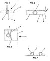
- a reinforcement 1 according to the invention includes a central core 2, the diameter of which varies according to the intended use. Diameters of between 2mm and 6mm are typical.
- a piece of stainless steel wire 3 Around the central core 2 is twisted a piece of stainless steel wire 3. The ends of the wire protrude radially from the reinforcement to form tails 4.
- Figure 2 shows the reinforcement 1 inserted into a relatively narrow groove 5.
- the reinforcement 1 is inserted with the tails 4 in a horizontal direction.
- the groove is filled with bonding material 6 which is preferably thixotropic and hardens irreversibly thus bonding the reinforcement 1 within the structure.
- the width of the stainless steel wire 3 is sufficient to support the central core in the groove such that it does not rest on the bottom or touch the top of the groove 5 even if there are irregularities in the shape or height of the groove. Because the central core is held away from the edges of the groove by the wire 3, the bonding material flows all around the central core and forms a strong bond.
- Figure 3 shows a bar 1 according to the invention in a somewhat wider groove 7.
- the bar 1 is twisted so that the tails 4 are no longer horizontal, but protrude almost vertically to jam against the upper and lower faces of the groove as the reinforcement is pushed into the groove.
- the reinforcement 1 is thus secured in the correct position and is suspended away from the upper and lower faces of the groove allowing the bonding material to flow around and to surround the reinforcement.
- the tails 4 hold the reinforcement firmly in place and prevent it from springing out of the groove as other parts of the reinforcement are being inserted.
- a tail 4 of the wire 3 may be extended to form a tie between two reinforcements for use in the two leaves of a cavity wall. It is often necessary to tie together the two leaves in this way to increase stability.
- Figure 5 shows the extension of the wire 3 to wrap around a further central core, forming a joint between a horizontal and vertical reinforcement.
- Figures 6 and 7 show a reinforcement having a spacer with an extended tail used as a bracket 8.
- the fixing of brackets to masonry structures can be difficult and this method is advantageous because it fixes the bracket securely to the reinforcement, which is held firmly within the masonry structure.
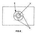
- Figure 8 shows a reinforcement including a spacer having four tails 4. Such spacers are particularly advantageous when the reinforcement is to be inserted in a hole 9 rather than a groove or slot.
- the reinforcements 1 are preferably inserted into a groove by fitting an insertion tool to a protruding tail 4, moving the reinforcement into position at the edge of a groove and tapping lightly with a hammer or similar instrument, moving along the length of the reinforcement.
- the reinforcement may be inserted into the inner leaf of a cavity wall by cutting through the outer leaf and making a groove in the inner leaf.
- An insertion tool is used to move the reinforcement through the cut in the outer leaf and to insert it into the groove in the inner leaf.
- the number of reinforcing bars inserted into one groove may vary according to the requirements of the design and the thickness of the wall.
- the wire loops and tails prevent the central cores 2 of the bars 1 from touching one another and ensure that the bond material flows around the full perimeter of the central core.
Landscapes
- Engineering & Computer Science (AREA)
- Architecture (AREA)
- Chemical & Material Sciences (AREA)
- Chemical Kinetics & Catalysis (AREA)
- Electrochemistry (AREA)
- Mechanical Engineering (AREA)
- Civil Engineering (AREA)
- Structural Engineering (AREA)
- Reinforcement Elements For Buildings (AREA)
- Working Measures On Existing Buildindgs (AREA)
- Moulding By Coating Moulds (AREA)
- Conveying And Assembling Of Building Elements In Situ (AREA)
Claims (15)
- Verfahren zum Verstärken einer Mauerwerks-Struktur, mit einem Schritt zum Schneiden eines Schlitzes, einer Rille oder eines Lochs (5, 7, 9) in der Struktur und Positionieren einer Verstärkung (1) darin, welche einen mittigen länglichen Kern (2) und eine Vielzahl von Abstandshaltern an dem mittigen Kern (2) enthält, um den mittigen Kern von den Rändern des Schlitzes, der Rille oder des Lochs fernzuhalten, wobei jeder Abstandshalter einen oder mehrere Vorsprünge (4) enthält, die sich radial auswärts von dem mittigen Kern (2) erstrecken, und wobei die Vorsprünge derart positioniert werden, dass sich bei horizontaler Ausrichtung der Verstärkung ihre maximale vertikale Ausdehnung verändert, wenn sie um ihre Achse verdreht wird.
- Verfahren nach Anspruch 1, dadurch gekennzeichnet, dass die Vorsprünge (4) so geformt sind, dass sie sich in dem Mauerwerk verhaken oder mit ihm in Eingriff gelangen.
- Verfahren nach Anspruch 1 oder 2, dadurch gekennzeichnet, dass jeder Abstandshalter zwei Vorsprünge (4) enthält, die näherungsweise diametral entgegengesetzt zueinander sind.
- Verfahren nach einem der vorhergehenden Ansprüche, dadurch gekennzeichnet, dass jeder Abstandshalter aus einem Drahtstück (3) besteht, das um den mittigen Kern (2) herum verdreht ist.
- Verfahren nach Anspruch 4, dadurch gekennzeichnet, dass der Draht aus rostfreiem Stahl besteht.
- Verfahren nach einem der vorhergehenden Ansprüche, dadurch gekennzeichnet, dass der mittige Kern (2) maschinell. bearbeitet ist oder eine aufgerauhte Oberfläche hat oder Grate enthält, um die Haftung zwischen dem mittigen Kern (2) und einem Abbindungsmaterial zu verstärken.
- Verfahren nach einem der vorhergehenden Ansprüche, dadurch gekennzeichnet, dass die Verstärkung (1) von einem biegsamen Schaftmaterial umgeben ist.
- Verfahren nach einem der vorhergehenden Ansprüche, dadurch gekennzeichnet, dass die Verstärkung (1) nach dem Einfügen in den Schlitz, die Rille oder das Loch (5, 7, 9) gespannt wird.
- Verstärkung (1) zum Einführen in einen Schlitz, eine Rille oder ein Loch (5, 7, 9) in einer Mauerwerks-Struktur, wobei die Verstärkung einen mittigen länglichen Kern und eine Vielzahl von Abstandshaltern an dem mittigen Kern (2) enthält, um den mittigen Kern von den Rändern des Schlitzes, der Rille oder des Lochs (5, 7, 9) fernzuhalten, wobei jeder Abstandshalter einen oder mehrere Vorsprünge (4) enthält, die sich von dem mittigen Kern radial nach außen erstrecken, wobei die Vorsprünge derart positioniert sind, dass sich bei horizontaler Ausrichtung der Verstärkung (1) ihre maximale vertikale Ausdehnung verändert, wenn sie um ihre Achse verdreht wird.
- Verstärkung (1) nach Anspruch 9, dadurch gekennzeichnet, dass die Vorsprünge (4) so geformt sind, dass sie sich in dem Mauerwerk verhaken oder mit ihm in Eingriff gelangen.
- Verstärkung (1) nach Anspruch 9 oder 10, dadurch gekennzeichnet, dass jeder Abstandshalter zwei Vorsprünge (4) enthält, die näherungsweise diametral gegenüberliegend zueinander sind.
- Verstärkung (1) nach einem der Ansprüche 9 bis 11, dadurch gekennzeichnet, dass jeder Abstandshalter aus einem Drahtstück (3) besteht, das um den mittigen Kern (2) herum verdreht ist.
- Verstärkung (1) nach Anspruch 12, dadurch gekennzeichnet, dass der Draht aus rostfreiem Stahl besteht.
- Verstärkung (1) nach einem der Ansprüche 9 bis 13, dadurch gekennzeichnet, dass der mittige Kern (2) maschinell bearbeitet ist oder an der Oberfläche aufgerauht ist oder Grate enthält, um die Haftung zwischen dem mittigen Kern und einem Abbindungsmaterial zu erhöhen.
- Verstärkung (1) nach einem der Ansprüche 9 bis 14, dadurch gekennzeichnet, dass die Verstärkung (1) von einem biegsamen Schaftmaterial umgeben ist.
Applications Claiming Priority (2)
| Application Number | Priority Date | Filing Date | Title |
|---|---|---|---|
| GBGB9611641.3A GB9611641D0 (en) | 1996-06-04 | 1996-06-04 | Method of positioning retrospective reinforcement in masonry structures |
| GB9611641 | 1996-06-04 |
Publications (2)
| Publication Number | Publication Date |
|---|---|
| EP0811736A1 EP0811736A1 (de) | 1997-12-10 |
| EP0811736B1 true EP0811736B1 (de) | 2003-09-03 |
Family
ID=10794731
Family Applications (1)
| Application Number | Title | Priority Date | Filing Date |
|---|---|---|---|
| EP97303835A Expired - Lifetime EP0811736B1 (de) | 1996-06-04 | 1997-06-04 | Armierung von Mauerwerk |
Country Status (4)
| Country | Link |
|---|---|
| EP (1) | EP0811736B1 (de) |
| AT (1) | ATE248971T1 (de) |
| DE (1) | DE69724514T2 (de) |
| GB (2) | GB9611641D0 (de) |
Families Citing this family (2)
| Publication number | Priority date | Publication date | Assignee | Title |
|---|---|---|---|---|
| ITVR20010034A1 (it) * | 2001-03-16 | 2002-09-16 | Maurizio Piazza | Metodo di produzione di una trave di legno armata e trave armata cosi' ottenuta |
| GB2569186B (en) * | 2017-12-11 | 2020-02-05 | George Edscer William | Method for the reinforcement of masonry structures |
Family Cites Families (9)
| Publication number | Priority date | Publication date | Assignee | Title |
|---|---|---|---|---|
| FR1135748A (fr) * | 1954-11-24 | 1957-05-03 | Chevalet-fixe pour le béton armé | |
| FR1358698A (fr) * | 1963-04-06 | 1964-04-17 | Avi Alpenlaendische Vered | élément d'armature et procédé pour le fabriquer |
| DE1940423A1 (de) * | 1969-06-12 | 1970-12-17 | Aldo Spirito | Draht bzw. Drahtseil zur Herstellung von vorgespanntem,armiertem Beton |
| GB2137273B (en) * | 1983-03-30 | 1986-08-06 | Alan Geoffrey Barnett | Improvements in or relating to wall ties |
| GB8419523D0 (en) * | 1984-07-31 | 1984-09-05 | Ollis W J B | Reinforcements and ties |
| DE3608775C2 (de) * | 1986-03-15 | 1995-03-16 | Int Intec Patent Holding Ets | In vorgebohrte Löcher einzusetzender Injektionsanker |
| EP0351668B1 (de) * | 1988-07-15 | 1992-10-14 | Mächtle GmbH | Fassadendübel |
| GB2249120B (en) * | 1991-01-26 | 1993-04-07 | Executive Insulation | Structural repair process |
| DE69621937T2 (de) * | 1995-08-18 | 2003-02-20 | Protec Industrial Ltd., Maidstone | Verstärkung von mauerwerkstrukturen |
-
1996
- 1996-06-04 GB GBGB9611641.3A patent/GB9611641D0/en active Pending
-
1997
- 1997-06-04 AT AT97303835T patent/ATE248971T1/de not_active IP Right Cessation
- 1997-06-04 DE DE69724514T patent/DE69724514T2/de not_active Expired - Lifetime
- 1997-06-04 GB GB9711488A patent/GB2313872B/en not_active Expired - Lifetime
- 1997-06-04 EP EP97303835A patent/EP0811736B1/de not_active Expired - Lifetime
Also Published As
| Publication number | Publication date |
|---|---|
| DE69724514D1 (de) | 2003-10-09 |
| GB2313872A (en) | 1997-12-10 |
| ATE248971T1 (de) | 2003-09-15 |
| EP0811736A1 (de) | 1997-12-10 |
| DE69724514T2 (de) | 2004-07-01 |
| GB9711488D0 (en) | 1997-07-30 |
| GB9611641D0 (en) | 1996-08-07 |
| GB2313872B (en) | 2000-09-27 |
Similar Documents
| Publication | Publication Date | Title |
|---|---|---|
| US4841703A (en) | Floor with co-operation between wood and concrete | |
| US7171788B2 (en) | Masonry connectors and twist-on hook and method | |
| EP0171250B1 (de) | Verfahren zum Herstellen eines Mauerbindeglieds und durch das Verfahren erzeugtes Bindeglied | |
| US11319706B1 (en) | FRP splice system for joining structural elements | |
| CA2260554A1 (en) | Reinforcement bar support system | |
| US5379562A (en) | Flow-through cap and stirrup for reinforcement bars and method of use thereof | |
| EP3779101B1 (de) | Verfahren zum erdbebenschutz von rahmen und füllwänden in rahmenkonstruktionen | |
| US6449914B1 (en) | Grout sealing apparatus for concrete panels, decks, and support beams and methods for their fabrication | |
| JP3786938B2 (ja) | コンクリート構造物の補強工法 | |
| EP0568548B1 (de) | Bausanierungsverfahren | |
| EP0811736A1 (de) | Armierung von Mauerwerk | |
| KR101815009B1 (ko) | 전도방지용 측면합성블록이 형성된 거더를 이용한 라멘교 시공방법 | |
| US6115979A (en) | Grout sealing apparatus for concrete panels, decks, and support beams and methods for their manufacture | |
| JP2003129676A (ja) | コンクリート躯体の補強方法 | |
| JPS6181979A (ja) | プレキャストpcタンクの施工法 | |
| US20050188648A1 (en) | Unreinforced masonry wall strengthening method and setup | |
| KR100442704B1 (ko) | 철근콘크리트 구조물의 외부 인장재 보강 방법 및 그구조 | |
| JPH07252884A (ja) | プレキャスト部材による架構の構築方法 | |
| JP4385127B2 (ja) | 斜面保護擁壁の施工方法及び擁壁築造ユニット | |
| JP7482587B2 (ja) | プレキャストコンクリート版部材の接合構造およびコンクリート板状構造の構築方法 | |
| KR101883167B1 (ko) | 케이블을 이용한 교량 구조물 내진보강공법 | |
| KR102831236B1 (ko) | 두꺼운 기둥과 보 연결부의 개량형 거푸집 구조 | |
| KR102831237B1 (ko) | 동일 폭의 기둥과 보 연결부의 개량형 거푸집 구조 | |
| JPH07292857A (ja) | 継手用異形鋼管を有するpc部材及びその接続方法 | |
| WO1999009277A1 (en) | Methods of reinforcing existing masonry structures |
Legal Events
| Date | Code | Title | Description |
|---|---|---|---|
| PUAI | Public reference made under article 153(3) epc to a published international application that has entered the european phase |
Free format text: ORIGINAL CODE: 0009012 |
|
| AK | Designated contracting states |
Kind code of ref document: A1 Designated state(s): AT BE DE FR GR IE IT |
|
| AX | Request for extension of the european patent |
Free format text: AL;LT;LV;SI |
|
| 17P | Request for examination filed |
Effective date: 19980523 |
|
| AKX | Designation fees paid |
Free format text: AT BE DE FR GR IE IT |
|
| RBV | Designated contracting states (corrected) |
Designated state(s): AT BE DE FR GR IE IT |
|
| 17Q | First examination report despatched |
Effective date: 20020315 |
|
| GRAH | Despatch of communication of intention to grant a patent |
Free format text: ORIGINAL CODE: EPIDOS IGRA |
|
| GRAS | Grant fee paid |
Free format text: ORIGINAL CODE: EPIDOSNIGR3 |
|
| GRAA | (expected) grant |
Free format text: ORIGINAL CODE: 0009210 |
|
| AK | Designated contracting states |
Kind code of ref document: B1 Designated state(s): AT BE DE FR GR IE IT |
|
| PG25 | Lapsed in a contracting state [announced via postgrant information from national office to epo] |
Ref country code: BE Free format text: LAPSE BECAUSE OF FAILURE TO SUBMIT A TRANSLATION OF THE DESCRIPTION OR TO PAY THE FEE WITHIN THE PRESCRIBED TIME-LIMIT Effective date: 20030903 Ref country code: AT Free format text: LAPSE BECAUSE OF FAILURE TO SUBMIT A TRANSLATION OF THE DESCRIPTION OR TO PAY THE FEE WITHIN THE PRESCRIBED TIME-LIMIT Effective date: 20030903 |
|
| REF | Corresponds to: |
Ref document number: 69724514 Country of ref document: DE Date of ref document: 20031009 Kind code of ref document: P |
|
| REG | Reference to a national code |
Ref country code: IE Ref legal event code: FG4D |
|
| PG25 | Lapsed in a contracting state [announced via postgrant information from national office to epo] |
Ref country code: GR Free format text: LAPSE BECAUSE OF FAILURE TO SUBMIT A TRANSLATION OF THE DESCRIPTION OR TO PAY THE FEE WITHIN THE PRESCRIBED TIME-LIMIT Effective date: 20031203 |
|
| PG25 | Lapsed in a contracting state [announced via postgrant information from national office to epo] |
Ref country code: IE Free format text: LAPSE BECAUSE OF NON-PAYMENT OF DUE FEES Effective date: 20040604 |
|
| ET | Fr: translation filed | ||
| PLBE | No opposition filed within time limit |
Free format text: ORIGINAL CODE: 0009261 |
|
| STAA | Information on the status of an ep patent application or granted ep patent |
Free format text: STATUS: NO OPPOSITION FILED WITHIN TIME LIMIT |
|
| 26N | No opposition filed |
Effective date: 20040604 |
|
| REG | Reference to a national code |
Ref country code: IE Ref legal event code: MM4A |
|
| PG25 | Lapsed in a contracting state [announced via postgrant information from national office to epo] |
Ref country code: IT Free format text: LAPSE BECAUSE OF NON-PAYMENT OF DUE FEES Effective date: 20100604 |
|
| PGRI | Patent reinstated in contracting state [announced from national office to epo] |
Ref country code: IT Effective date: 20110616 |
|
| REG | Reference to a national code |
Ref country code: FR Ref legal event code: PLFP Year of fee payment: 20 |
|
| PGFP | Annual fee paid to national office [announced via postgrant information from national office to epo] |
Ref country code: IT Payment date: 20160427 Year of fee payment: 20 Ref country code: FR Payment date: 20160616 Year of fee payment: 20 |
|
| PGFP | Annual fee paid to national office [announced via postgrant information from national office to epo] |
Ref country code: DE Payment date: 20160621 Year of fee payment: 20 |
|
| REG | Reference to a national code |
Ref country code: DE Ref legal event code: R071 Ref document number: 69724514 Country of ref document: DE |