EP0811781A2 - Dispositif pour amortir et supprimer les bruits de freinage - Google Patents
Dispositif pour amortir et supprimer les bruits de freinage Download PDFInfo
- Publication number
- EP0811781A2 EP0811781A2 EP97108613A EP97108613A EP0811781A2 EP 0811781 A2 EP0811781 A2 EP 0811781A2 EP 97108613 A EP97108613 A EP 97108613A EP 97108613 A EP97108613 A EP 97108613A EP 0811781 A2 EP0811781 A2 EP 0811781A2
- Authority
- EP
- European Patent Office
- Prior art keywords
- component
- damping
- damped
- spring element
- vibration
- Prior art date
- Legal status (The legal status is an assumption and is not a legal conclusion. Google has not performed a legal analysis and makes no representation as to the accuracy of the status listed.)
- Withdrawn
Links
Images


Classifications
-
- F—MECHANICAL ENGINEERING; LIGHTING; HEATING; WEAPONS; BLASTING
- F16—ENGINEERING ELEMENTS AND UNITS; GENERAL MEASURES FOR PRODUCING AND MAINTAINING EFFECTIVE FUNCTIONING OF MACHINES OR INSTALLATIONS; THERMAL INSULATION IN GENERAL
- F16D—COUPLINGS FOR TRANSMITTING ROTATION; CLUTCHES; BRAKES
- F16D65/00—Parts or details
- F16D65/14—Actuating mechanisms for brakes; Means for initiating operation at a predetermined position
- F16D65/16—Actuating mechanisms for brakes; Means for initiating operation at a predetermined position arranged in or on the brake
- F16D65/22—Actuating mechanisms for brakes; Means for initiating operation at a predetermined position arranged in or on the brake adapted for pressing members apart, e.g. for drum brakes
-
- F—MECHANICAL ENGINEERING; LIGHTING; HEATING; WEAPONS; BLASTING
- F16—ENGINEERING ELEMENTS AND UNITS; GENERAL MEASURES FOR PRODUCING AND MAINTAINING EFFECTIVE FUNCTIONING OF MACHINES OR INSTALLATIONS; THERMAL INSULATION IN GENERAL
- F16D—COUPLINGS FOR TRANSMITTING ROTATION; CLUTCHES; BRAKES
- F16D65/00—Parts or details
- F16D65/0006—Noise or vibration control
- F16D65/0018—Dynamic vibration dampers, e.g. mass-spring systems
Definitions
- the invention relates to a device for damping and absorbing brake noise.
- a noise damper is known, an additional mass being pressed resiliently onto the vibrating component.
- a disadvantage of this prior art is that the noise damper is only effective at a certain frequency, so that noises of another frequency remain largely undamped.
- the object of the present invention is therefore to provide a device for damping and absorbing brake noises, which releases brake noises in all operating states and for all brake types reliably and in the long term.
- This object is achieved by at least one vibration-damping component and at least one vibration-damping component interacting with it.
- a functionally necessary component is provided as a vibration-damping component.
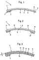
- a device 1 for damping and absorbing brake noise comprises at least one vibration-damping component 2, which is arranged as a damping element 3 on the noise damping device 1.
- the device 1 also comprises at least one vibration-damping component 4 which interacts with the vibration-damping component 2.
- the vibration-damping component 4 is designed as a spring element 5 with a leg 6 and has a defined mass and spring stiffness.
- the damping element 3 is located on one leg end 7 and is pressed elastically by the spring element 5 against the component to be damped.
- the damping element 3 is thus located between the component to be damped and the spring element 5.
- other types of fastening such as welding or soldering are also conceivable.
- FIG. 2 shows a noise insulation device 1, components that correspond to FIG. 1 being provided with the same reference numbers.
- the spring element 5 has a centrally located fastening point 9 with two laterally arranged legs 6 ', 6''.
- the attachment point is adapted to the respective requirements and, in principle, eccentric arrangements are also possible.
- Each leg 6 ', 6'' has at its leg end 7', 7 '' a damping element 3 ', 3'', which acts on the component to be damped due to the spring preload.
- the spring element 5 is curved, as in FIG. 1, and the concave side is preferably turned towards the component to be damped during assembly on a braking device.
- the spring element By adapting to the component to be damped, for producing a specific spring rate or a specific spring travel, however, a variety of shapes are conceivable without departing from the inventive concept. It is in particular possible to design the spring element to be flat or convexly curved. In principle, all materials can be used as the material for the damping element 3, and particularly good results can be achieved with plastic materials and rubber materials such as EPDM.
- Fig. 3 shows a device 1, which differs in particular from Fig. 1 in that a vibration-damping component 4 is provided in the manner of a leaf spring assembly with several layers.
- the number of layers 11, 12, 13, 14 and their thickness d is arbitrary and can be adapted to the prevailing operating conditions and the desired spring action.
- the layers 11, 12, 13, 14 preferably have a different thickness d and are fastened to one another, for example, with the aid of adhesive intermediate layers 15.
- the multilayer structure leads to a damping effect which is integrated into the spring element 5 and supports the damping element 3.
- the internal damping of the spring element 5 makes a separate damping element 3 superfluous.
- the so-called joint damping is influenced by specifically selecting certain types of adhesive or by setting a certain adhesive layer thickness. Otherwise, the spring rate depends on the material and the shape of the layers 11, 12, 13, 14.
- two fundamentally identical devices 1 are arranged on a schematically drawn component 16 of a braking device, for example a brake housing or a brake carrier.
- a braking device for example a brake housing or a brake carrier.
- Each device is fastened to the component 16 by means of fastening points 9, preferably screwed on, and act on the free ends 17 of arms 18 arranged on the component 16 with the damping elements 3 'provided on the leg ends 7'.
- one part of the component 16 becomes large Vibration amplitudes applied.
- FIG. 5 shows a component 19 in the form of a brake cylinder which is arranged elastically on a supporting holding element 20.
- This elasticity is achieved by an intermediate layer 21 arranged between the component 19 and the holding element 20 and a spring element 22 which braces the component 19 with respect to the holding element 20. Vibrations of the holding element 20 lead to an excitation of the component 19 and to damped vibrations relative to the holding element 20. It should be noted that in this device no additional mass is used for vibration damping, but the mass of an essential, functionally necessary component.
- the intermediate layer 21 acts as a vibration-damping component and the component 19 acts as a vibration-damping component.
- FIG. 6 and 7 show a further exemplary embodiment, the same components having the same reference numbers as in FIG. 5.
- the component 19 in the manner of a brake cylinder is in this embodiment using a annular spring element 22 is arranged on the holding element 20 and can execute vibrations relative to the holding element 20.
- the spring element 22 has the shape of a ring 23 which bears against a mounting flange 24 for the brake cylinder and also engages behind it.
- the spring element 22 also has two resilient tongues 25, 26 which point radially inward into an opening and on which the brake cylinder is fastened.
Landscapes
- Engineering & Computer Science (AREA)
- General Engineering & Computer Science (AREA)
- Mechanical Engineering (AREA)
- Braking Arrangements (AREA)
- Vibration Prevention Devices (AREA)
Applications Claiming Priority (2)
| Application Number | Priority Date | Filing Date | Title |
|---|---|---|---|
| DE19622546 | 1996-06-05 | ||
| DE1996122546 DE19622546A1 (de) | 1996-06-05 | 1996-06-05 | Vorrichtung zum Dämpfen und Tilgen von Bremsgeräuschen |
Publications (2)
| Publication Number | Publication Date |
|---|---|
| EP0811781A2 true EP0811781A2 (fr) | 1997-12-10 |
| EP0811781A3 EP0811781A3 (fr) | 1998-01-28 |
Family
ID=7796208
Family Applications (1)
| Application Number | Title | Priority Date | Filing Date |
|---|---|---|---|
| EP97108613A Withdrawn EP0811781A3 (fr) | 1996-06-05 | 1997-05-28 | Dispositif pour amortir et supprimer les bruits de freinage |
Country Status (2)
| Country | Link |
|---|---|
| EP (1) | EP0811781A3 (fr) |
| DE (1) | DE19622546A1 (fr) |
Cited By (6)
| Publication number | Priority date | Publication date | Assignee | Title |
|---|---|---|---|---|
| WO1998021499A1 (fr) * | 1996-11-09 | 1998-05-22 | Automotive Products Plc | Cylindres de frein sur roue |
| WO1999039112A1 (fr) * | 1998-01-28 | 1999-08-05 | Continental Teves Ag & Co. Ohg | Element elastique pour un frein a disque |
| EP1688636A3 (fr) * | 2005-02-02 | 2006-08-16 | ROBERT BOSCH GmbH | Dispositif anti-vibratoire et structure comportant untel dispositif |
| US7604098B2 (en) * | 2005-08-01 | 2009-10-20 | Gm Global Technology Operations, Inc. | Coulomb friction damped disc brake caliper bracket |
| EP2199638A1 (fr) * | 2008-12-19 | 2010-06-23 | Robert Bosch GmbH | Frein à tambour |
| WO2014139739A1 (fr) * | 2013-03-14 | 2014-09-18 | Chassis Brakes International B.V. | Frein à tambour comportant un cylindre de roue avec une surface d'appui réduite sur le plateau et avec interposition d'un élément de guidage entre le cylindre et le plateau |
Families Citing this family (4)
| Publication number | Priority date | Publication date | Assignee | Title |
|---|---|---|---|---|
| DE19925004A1 (de) * | 1999-05-31 | 2000-12-07 | Porsche Ag | Bremssattel für eine Scheibenbremsanlage |
| DE10106177B4 (de) * | 2001-02-10 | 2013-02-21 | Dr. Ing. H.C. F. Porsche Aktiengesellschaft | Scheibenbremse für Fahrzeuge, insbesondere Kraftfahrzeuge |
| DE10306137B4 (de) * | 2003-02-14 | 2008-07-10 | Audi Ag | Bremssattel |
| DE102014001061A1 (de) * | 2014-01-28 | 2015-07-30 | Lucas Automotive Gmbh | Scheibenbremse umfassend eine Schwingungsdämpfungseinrichtung mit einer Zusatzmasse und Bausatz mit einer derartigen Scheibenbremse |
Family Cites Families (17)
| Publication number | Priority date | Publication date | Assignee | Title |
|---|---|---|---|---|
| US1910590A (en) * | 1930-09-17 | 1933-05-23 | Charles Hubert Noel | Vehicle brake |
| DE1117417B (de) * | 1960-03-25 | 1961-11-16 | Daimler Benz Ag | Dynamischer Schwingungsdaempfer, insbesondere fuer Kraftfahrzeuge |
| US3200908A (en) * | 1963-06-05 | 1965-08-17 | Bendix Corp | Fluid motor, backing plate connection |
| DE2250742A1 (de) * | 1972-10-17 | 1974-04-18 | Bendix Gmbh | Teilbelagscheibenbremse |
| DE2631146C2 (de) * | 1976-07-10 | 1984-12-20 | Alfred Teves Gmbh, 6000 Frankfurt | Schwimmsattelführung für eine Teilbelag-Scheibenbremse |
| DE2914629C2 (de) * | 1979-04-11 | 1983-12-29 | M.A.N. Maschinenfabrik Augsburg-Nürnberg AG, 8000 München | Schwingungsgedämpfter Bremsbacken für eine Omnibus-Trommmelbremse |
| US4227594A (en) * | 1979-04-25 | 1980-10-14 | The Bendix Corporation | Backing plate-wheel cylinder retaining clip |
| FR2525713B1 (fr) * | 1982-04-21 | 1986-09-19 | Dba | Dispositif amortisseur pour frein a tambour, plaque support de frein incorporant un tel dispositif et frein a tambour comportant une plaque support equipee d'un tel dispositif |
| DE3736126A1 (de) * | 1987-10-26 | 1989-05-11 | Porsche Ag | Bremsvorrichtung |
| GB8817007D0 (en) * | 1988-07-16 | 1988-08-17 | Bba Group Plc | Drum brake assembly |
| GB2221265A (en) * | 1988-07-30 | 1990-01-31 | Automotive Products Plc | Drum brakes |
| DE3918369A1 (de) * | 1989-01-31 | 1990-08-02 | Teves Gmbh Alfred | Scheibenbremse |
| IT1240022B (it) * | 1990-04-30 | 1993-11-27 | Alfa Lancia Spa | Staffa di supporto per pinze flottanti a smorzamento di vibrazioni |
| DE4020668A1 (de) * | 1990-06-29 | 1992-01-02 | Teves Gmbh Alfred | Geraeuscharmer schwimmsattel fuer teilbelagscheibenbremsen |
| DE4021567A1 (de) * | 1990-07-06 | 1992-01-09 | Teves Gmbh Alfred | Geraeuschdaempfer fuer scheiben- oder trommelbremse |
| DE4036401A1 (de) * | 1990-07-06 | 1992-05-21 | Teves Gmbh Alfred | Geraeuschdaempfer fuer scheibenbremsen |
| RU2001327C1 (ru) * | 1991-06-24 | 1993-10-15 | зев Виктор Владимирович Кн | Амортизирующее устройство |
-
1996
- 1996-06-05 DE DE1996122546 patent/DE19622546A1/de not_active Withdrawn
-
1997
- 1997-05-28 EP EP97108613A patent/EP0811781A3/fr not_active Withdrawn
Cited By (14)
| Publication number | Priority date | Publication date | Assignee | Title |
|---|---|---|---|---|
| GB2323645A (en) * | 1996-11-09 | 1998-09-30 | Automotive Products Plc | Brake wheel cylinders |
| GB2323645B (en) * | 1996-11-09 | 2000-08-09 | Automotive Products Plc | Brake wheel cylinders |
| WO1998021499A1 (fr) * | 1996-11-09 | 1998-05-22 | Automotive Products Plc | Cylindres de frein sur roue |
| DE19803123B4 (de) * | 1998-01-28 | 2015-06-11 | Continental Teves Ag & Co. Ohg | Scheibenbremse mit einem Federelement |
| WO1999039112A1 (fr) * | 1998-01-28 | 1999-08-05 | Continental Teves Ag & Co. Ohg | Element elastique pour un frein a disque |
| EP1688636A3 (fr) * | 2005-02-02 | 2006-08-16 | ROBERT BOSCH GmbH | Dispositif anti-vibratoire et structure comportant untel dispositif |
| US7604098B2 (en) * | 2005-08-01 | 2009-10-20 | Gm Global Technology Operations, Inc. | Coulomb friction damped disc brake caliper bracket |
| EP2199638A1 (fr) * | 2008-12-19 | 2010-06-23 | Robert Bosch GmbH | Frein à tambour |
| FR2940383A1 (fr) * | 2008-12-19 | 2010-06-25 | Bosch Gmbh Robert | Frein a tambour et plateau de frein a tambour a lame de prec ontrainte |
| WO2014139739A1 (fr) * | 2013-03-14 | 2014-09-18 | Chassis Brakes International B.V. | Frein à tambour comportant un cylindre de roue avec une surface d'appui réduite sur le plateau et avec interposition d'un élément de guidage entre le cylindre et le plateau |
| FR3003322A1 (fr) * | 2013-03-14 | 2014-09-19 | Chassis Brakes Int Bv | "frein a tambour comportant un cylindre de roue avec une surface d'appui reduite sur le plateau et avec interposition d'un element de guidage entre le cylindre et le plateau" |
| CN105229328A (zh) * | 2013-03-14 | 2016-01-06 | 泛博制动国际有限公司 | 包括轮缸的具有板上缩减支承表面及置于轮缸与板间的引导元件的鼓式制动器 |
| JP2016507039A (ja) * | 2013-03-14 | 2016-03-07 | シャシー・ブレークス・インターナショナル・ベスローテン・フェンノートシャップ | プレート上に縮小された軸受面を備え、シリンダとプレートとの間に介在するガイド要素を備えるホイール・シリンダを備えるドラム・ブレーキ |
| CN105229328B (zh) * | 2013-03-14 | 2017-12-19 | 泛博制动国际有限公司 | 用于机动车辆的鼓式制动器 |
Also Published As
| Publication number | Publication date |
|---|---|
| DE19622546A1 (de) | 1997-12-11 |
| EP0811781A3 (fr) | 1998-01-28 |
Similar Documents
| Publication | Publication Date | Title |
|---|---|---|
| DE3421804C2 (de) | Hydraulisch gedämpftes Kraftfahrzeugmotorlager | |
| DE3128340C2 (fr) | ||
| EP1113950A1 (fr) | Volant equipe d'un module sac gonflable | |
| EP3768559B1 (fr) | Ensemble formant volant de direction | |
| EP0811781A2 (fr) | Dispositif pour amortir et supprimer les bruits de freinage | |
| DE19653684C2 (de) | Anordnung zur Befestigung einer Airbageinheit am Lenkrad | |
| DE102005009677A1 (de) | Schwingungstilger | |
| DE3443910A1 (de) | Schwingungsdaempfer | |
| EP3645346A1 (fr) | Bague d'amortisseur de vibrations et module à coussin gonflable comprenant une telle bague d'amortisseur de vibrations | |
| EP0230685B1 (fr) | Fixation de l'amortisseur dans une machine à laver | |
| DE69012916T2 (de) | Elastisches Auflager mit eingebautem Phasenverschieber, insbesondere für Kraftfahrzeugmotoren. | |
| WO2000014428A1 (fr) | Amortisseur de chocs et de vibrations, notamment pour suspendre des circuits d'echappement d'automobiles | |
| DE4219820C2 (de) | Schwingungsdämpfer | |
| DE10312977A1 (de) | Federelement | |
| DE10248948B4 (de) | Scheibenbremse, insbesondere für ein Nutzfahrzeug | |
| DE3508098A1 (de) | Bowdenzug | |
| EP0439685A1 (fr) | Support en forme de manchon | |
| DE19632183A1 (de) | Federbein mit Dämpfung zwischen Schraubenfeder und Federteller | |
| DE602006000829T2 (de) | Schwingungsdämpfende Vorrichtung und Struktur mit dieser | |
| DE102007042003A1 (de) | Schwingungstilger für eine Kraftfahrzeugkomponente | |
| DE19740799B4 (de) | Dämpfungselement | |
| DE102022107271B4 (de) | Kraftfahrzeug mit einem Schwingungstilger | |
| DE3516313A1 (de) | Elastisches lagerelement fuer antriebsaggregate in kraftfahrzeugen | |
| EP1167808A2 (fr) | Support en élastomère | |
| DE102006059096B4 (de) | Baugruppe zur fahrzeugseitigen Befestigung eines Gurtschlosses |
Legal Events
| Date | Code | Title | Description |
|---|---|---|---|
| PUAI | Public reference made under article 153(3) epc to a published international application that has entered the european phase |
Free format text: ORIGINAL CODE: 0009012 |
|
| AK | Designated contracting states |
Kind code of ref document: A2 Designated state(s): DE ES FR GB IT |
|
| PUAL | Search report despatched |
Free format text: ORIGINAL CODE: 0009013 |
|
| AK | Designated contracting states |
Kind code of ref document: A3 Designated state(s): DE ES FR GB IT |
|
| 17P | Request for examination filed |
Effective date: 19980728 |
|
| RAP1 | Party data changed (applicant data changed or rights of an application transferred) |
Owner name: CONTINENTAL TEVES AG & CO. OHG |
|
| 17Q | First examination report despatched |
Effective date: 20001113 |
|
| STAA | Information on the status of an ep patent application or granted ep patent |
Free format text: STATUS: THE APPLICATION IS DEEMED TO BE WITHDRAWN |
|
| 18D | Application deemed to be withdrawn |
Effective date: 20010324 |