EP0811784A2 - Aktiver Schwingungsdämpfer - Google Patents
Aktiver Schwingungsdämpfer Download PDFInfo
- Publication number
- EP0811784A2 EP0811784A2 EP97107426A EP97107426A EP0811784A2 EP 0811784 A2 EP0811784 A2 EP 0811784A2 EP 97107426 A EP97107426 A EP 97107426A EP 97107426 A EP97107426 A EP 97107426A EP 0811784 A2 EP0811784 A2 EP 0811784A2
- Authority
- EP
- European Patent Office
- Prior art keywords
- component
- vibration
- vibration reducer
- actuator
- reducer according
- Prior art date
- Legal status (The legal status is an assumption and is not a legal conclusion. Google has not performed a legal analysis and makes no representation as to the accuracy of the status listed.)
- Granted
Links
- 239000003638 chemical reducing agent Substances 0.000 claims abstract description 33
- 230000005540 biological transmission Effects 0.000 claims abstract description 5
- 230000001419 dependent effect Effects 0.000 claims abstract description 5
- 230000005284 excitation Effects 0.000 abstract description 26
- 238000010276 construction Methods 0.000 abstract description 5
- 230000001629 suppression Effects 0.000 abstract description 3
- 230000000694 effects Effects 0.000 description 3
- 238000005265 energy consumption Methods 0.000 description 2
- 230000000737 periodic effect Effects 0.000 description 2
- 230000006978 adaptation Effects 0.000 description 1
- 238000010586 diagram Methods 0.000 description 1
- 239000003814 drug Substances 0.000 description 1
- 229940079593 drug Drugs 0.000 description 1
- 230000008029 eradication Effects 0.000 description 1
- 238000009413 insulation Methods 0.000 description 1
- 238000002955 isolation Methods 0.000 description 1
- 230000010355 oscillation Effects 0.000 description 1
- 230000001105 regulatory effect Effects 0.000 description 1
- 230000000007 visual effect Effects 0.000 description 1
Images

Classifications
-
- F—MECHANICAL ENGINEERING; LIGHTING; HEATING; WEAPONS; BLASTING
- F16—ENGINEERING ELEMENTS AND UNITS; GENERAL MEASURES FOR PRODUCING AND MAINTAINING EFFECTIVE FUNCTIONING OF MACHINES OR INSTALLATIONS; THERMAL INSULATION IN GENERAL
- F16F—SPRINGS; SHOCK-ABSORBERS; MEANS FOR DAMPING VIBRATION
- F16F7/00—Vibration-dampers; Shock-absorbers
- F16F7/10—Vibration-dampers; Shock-absorbers using inertia effect
- F16F7/1005—Vibration-dampers; Shock-absorbers using inertia effect characterised by active control of the mass
- F16F7/1011—Vibration-dampers; Shock-absorbers using inertia effect characterised by active control of the mass by electromagnetic means
-
- F—MECHANICAL ENGINEERING; LIGHTING; HEATING; WEAPONS; BLASTING
- F16—ENGINEERING ELEMENTS AND UNITS; GENERAL MEASURES FOR PRODUCING AND MAINTAINING EFFECTIVE FUNCTIONING OF MACHINES OR INSTALLATIONS; THERMAL INSULATION IN GENERAL
- F16F—SPRINGS; SHOCK-ABSORBERS; MEANS FOR DAMPING VIBRATION
- F16F15/00—Suppression of vibrations in systems; Means or arrangements for avoiding or reducing out-of-balance forces, e.g. due to motion
- F16F15/02—Suppression of vibrations of non-rotating, e.g. reciprocating systems; Suppression of vibrations of rotating systems by use of members not moving with the rotating systems
- F16F15/03—Suppression of vibrations of non-rotating, e.g. reciprocating systems; Suppression of vibrations of rotating systems by use of members not moving with the rotating systems using magnetic or electromagnetic means
Definitions
- the invention relates to an active vibration reducer for reducing the vibration transmission from a dynamically loaded component to a supporting structure supporting it.
- Vibration reducers of this type can be used wherever periodic excitation is to be isolated or erased, in particular also in helicopters, in order to keep the dynamic loads acting on the rotor / gear system away from the helicopter cell.
- US Pat. No. 3,322,379, CA 781 817 or DE 29 07 926 disclose passive vibration isolators with a spring pendulum that is mechanically or hydraulically excited by the vibrating component. which is so coordinated that there is a local cancellation of the dynamic force components at the cell-side attachment point, so that in the anti-resonance case practically no more vibrations are transmitted from the rotor transmission system to the helicopter cell.
- vibration isolators have a system-dependent invariant anti-resonance frequency and an extremely narrow-band insulation effect and have a very large construction volume and weight, which is a serious disadvantage, particularly in view of the strict weight restrictions and restricted space, especially in helicopter construction.
- EP 519 786 B1 discloses an active vibration reducer with a double-acting hydraulic force actuator arranged between the helicopter gearbox and cell, which is servo-valve-controlled in accordance with the excitation vibration of the helicopter gearbox and generates opposing alternating forces to the dynamic loads acting on it.
- a vibration reducer requires a structurally complex, powerful power generator and is unsuitable for many applications due to its high external energy requirement, which is in the order of magnitude of the dynamic force components acting on it.
- the object of the invention is to provide an active vibration reducer of the type mentioned, which has a structurally simple, weight-saving design and guarantees a highly effective vibration reduction with a low external energy consumption.
- the arrangement of a spring pendulum excited by the dynamic component loads in conjunction with an actuator which additionally excites the spring pendulum in accordance with a force which excites vibrations significantly reduces the pendulum mass required to reduce visual oscillation and thereby the construction volume and weight of the vibration reducer, and at the same time the required actuator force and thus the external energy consumption to a fraction the excitation forces acting on the component side are reduced, with the special feature that the vibration reducer according to the invention not only has a singular anti-resonance frequency due to the combined intrinsic and external excitation of the spring pendulum, but already has a pronounced anti-resonance effect in a relatively broadband frequency range and moreover has no problem, namely solely by Change in the force amplitude of the actuator can be set to a variable anti-resonance frequency within wide limits.
- the effective relationship between the force amplitude of the actuator and the anti-resonance frequency is used in the manner specified in claim 2 for a continuous, automatic adaptation of the vibration reducer to frequency-variable, dynamic component loads. This ensures a high degree of vibration suppression in the entire operation area of the helicopter, especially in modern helicopter rotor systems that are operated in an extended speed range.
- Sensor for the force amplitude control of the actuator is sufficient, as preferred according to claim 3, a simple piezo element.
- a resilient support of the component on the support structure can even produce multiple, discrete anti-resonance points, which is particularly important for helicopters where, in addition to the first blade number harmonics, higher harmonic rotor excitations are also effective is.
- the spring pendulum according to claim 5 expediently consists of a linearly freely suspended pendulum mass between the component and the support structure, and the reaction force of the actuator is preferably supported on the support structure according to claim 6.
- the reaction force of the actuator according to claim 7 is in a particularly preferred manner resiliently offset on the support structure or the component, whereby a more refined adjustment of the frequency spacing of the anti-resonance points is possible.
- the pendulum mass and the actuator are formed by an electrically controlled magnet coil arrangement and thereby easily adjustable to a power amplitude and frequency with regard to external force Assembly summarized, the magnetic coil arrangement according to claim 9 is preferably double-acting in view of an improved performance.
- the vibration reducer 2 shown in FIG. 1 is arranged between a component 4 which is loaded periodically in the direction of arrow A, for example the main gear of a helicopter rotor system, and a support structure 6, for example the helicopter cell, and contains the main components in the direction A of the dynamic loads free-swinging spring pendulum 8 in combination with an electrically controllable actuator 10 which excites the spring pendulum 8 and which are housed in a common housing 12 which connects the component-side fastening point 14 essentially rigidly to the cell-side fastening point 16 of the vibration reducer 2.
- the spring pendulum-actuator combination 8, 10 consists of a double-acting magnet coil arrangement 18, the magnet coil 20 of which forms the pendulum mass of the spring pendulum 8, which is freely oscillating linearly via spring elements 22, 24, while the armature 26 of the magnet coil arrangement 18 is firmly connected to the housing 12.
- the periodic excitation force at the fastening point 14 on the component side leads to harmonic natural vibrations of the spring pendulum 8 consisting of the magnet coil 20 and the springs 22, 24.
- precisely controlled dynamic alternating forces are generated by the phase-conforming, electrical external force excitation of the magnet coil 20, which amplify the coil inertia force and thus the component-side force Keep excitation forces away from cell-side attachment point 16 by eradication or isolation.
- the transmission behavior of the system is dependent on the design parameters, in particular the spring characteristics of the spring elements 22, 24, the mass of the magnet coil 20, the size of the excitation forces acting on the component side, the mass of the support structure 6 and the vibrating component 4 and the amplitude of the magnetic alternating force.
- Curve a corresponds to the natural vibration behavior of the vibration reducer 2 without magnetic force excitation of the spring pendulum 8.
- a singular excitation frequency of approximately 23 Hz theoretically an anti-resonance drug results, which, however, cannot be used technically due to the selected mass ratios.
- the influence of the magnetic force excitation on the system behavior can be seen from the curves b, c and d, staggered according to the increasing magnetic force amplitude. It can be seen that the vibration reducer 2 now has a pronounced anti-resonance behavior, the position of the anti-resonance point depending on the force amplitude of the magnetic force actuator 10.
- the anti-resonance effect is not limited to a singular excitation frequency, but extends over a wide frequency range in which the curves b, c and d run clearly below the magnetic force-free comparison curve a and thus a significant vibration reduction is present.
- the anti-resonance point of the vibration reducer 2 can be shifted to a desired frequency by changing the force ratio F M / F R.
- the anti-resonance point in the underlying calculation example moves from approx. 24 Hz (curve b) to approx. 27 Hz (curve d) if the force ratio F M / F R is increased from 0.1 to 0.3.
- the anti-resonance frequency is generally set to the first rotor number excitation, that is to say in the case of a four-blade rotor, to 4 ⁇ .
- the tuning equation above possible to automatically adjust the anti-resonance point of the vibration reducer 2 to the speed variations of the rotor.
- the vibration reducer 2 is assigned a control stage 28 including a sensor 30, for example in the form of a piezo element, which also measures the frequency of the rotor-side excitation force F R in addition to the amplitude.
- the excitation current for the two coil halves 20.1 and 20.2 is varied using the tuning equation or using a data map in such a way that the anti-resonance point of the vibration reducer 2 adapts to the rotor excitation frequency.
- the housing 112 is designed to be spring-elastic (at 32) in the direction of the dynamic component loads and the Armature 126 of the magnetic force actuator 110 is also resiliently supported on the housing 112, namely via a plate spring element 34.
- the magnetic force excitation is in turn regulated by a control unit 128 either in the sense of a constant force ratio F M / F R or for variable rotor speeds and thus excitation frequencies in the sense of an excitation frequency-dependent magnetic force amplitude on the basis of a tuning equation modified taking into account the resilient housing support.
- a control unit 128 either in the sense of a constant force ratio F M / F R or for variable rotor speeds and thus excitation frequencies in the sense of an excitation frequency-dependent magnetic force amplitude on the basis of a tuning equation modified taking into account the resilient housing support.
- the construction and mode of operation of the vibration reducer 102 is the same as in the first exemplary embodiment.
Landscapes
- Engineering & Computer Science (AREA)
- General Engineering & Computer Science (AREA)
- Physics & Mathematics (AREA)
- Electromagnetism (AREA)
- Mechanical Engineering (AREA)
- Acoustics & Sound (AREA)
- Aviation & Aerospace Engineering (AREA)
- Vibration Prevention Devices (AREA)
Abstract
Description
- Die Erfindung bezieht sich auf einen aktiven Schwingungsminderer zum Reduzieren der Schwingungsübertragung von einem dynamisch belasteten Bauteil an eine dieses abstützende Tragstruktur.
- Derartige Schwingungsminderer können überall dort eingesetzt werden, wo eine periodische Erregung isoliert oder getilgt werden soll, insbesondere auch bei Hubschraubern, um die vom Rotor-Getriebe-System einwirkenden dynamischen Belastungen von der Hubschrauberzelle fernzuhalten.
- Aus der US 3 322 379, der CA 781 817 oder der DE 29 07 926 sind zu diesem Zweck passive Schwingungsisolatoren mit einem vom schwingenden Bauteil mechanisch oder hydraulisch erregten Federpendel bekannt, welches so abgestimmt ist, daß lokal eine Aufhebung der dynamischen Kraftanteile am zellenseitigen Befestigungspunkt erfolgt, so daß im Antiresonanzfall praktisch keine Schwingungen mehr vom Rotor-Getriebesystem auf die Hubschrauberzelle übertragen werden. Derartige Schwingungsisolatoren haben jedoch eine systembedingt invariante Antiresonanzfrequenz und eine äußerst schmalbandige Isolationswirkung und besitzen ein sehr großes Bauvolumen und Eigengewicht, was gerade im Hinblick auf die strikten Gewichtsbeschränkungen und beengten Platzverhältnisse insbesondere im Hubschrauberbau ein gravierender Nachteil ist.
- Ferner ist aus der EP 519 786 B1 ein aktiver Schwingungsminderer mit einem zwischen Hubschraubergetriebe und -zelle angeordneten, doppeltwirkenden hydraulischen Kraftaktuator bekannt, der nach Maßgabe der Erregerschwingung des Hubschraubergetriebes servoventilgesteuert ist und den einwirkenden dynamischen Belastungen entgegengerichtete Wechselkräfte erzeugt. Ein solcher Schwingungsminderer aber benötigt einen baulich aufwendigen, leistungsstarken Kraftgenerator und ist wegen seines hohen Fremdenergiebedarfs, der in der Größenordnung der einwirkenden dynamischen Kraftanteile liegt, für viele Auwendungsfälle ungeeignet.
- Aufgabe der Erfindung ist es, einen aktiven Schwingungsminderer der eingangs genannten Art zu schaffen, der eine konstruktiv einfache, gewichtssparende Bauweise besitzt und eine hochwirksame Schwingungsreduktion mit einem geringen Fremdenergieverbrauch garantiert.
- Diese Aufgabe wird erfindungsgemäß durch den im Patentanspruch 1 angegebenen Schwingungsminderer gelöst.
- Erfindungsgemäß werden durch die Anordnung eines von den dynamischen Bauteilbelastungen erregten Federpendels in Verbindung mit einem das Federpendel zusätzlich schwingungskonform fremdkrafterregenden Aktuator die zur Sehwingungsminderung erforderliche Pendelmasse und dadurch das Bauvolumen und -gewicht des Schwingungsminderers deutlich verringert und zugleich die benötigte Aktuatorkraft und somit der Fremdenergieverbrauch auf einen Bruchteil der bauteilseitig einwirkenden Erregerfräfte reduziert, mit der Besonderheit, daß der erfindungsgemäße Schwingungsminderer aufgrund der kombinierten Eigen- und Fremderregung des Federpendels nicht nur eine singuläre Antiresonanzfrequenz besitzt, sondern in einem relativ breitbandigen Frequenzbereich bereits eine ausgeprägte Antiresonanzwirkung aufweist und sich darüber hinaus problemlos, nämlich allein durch Änderung der Kraftamplitude des Aktuators, auf eine in weiten Grenzen variable Antiresonanzfrequenz einstellen läßt.
- In weiterer vorteilhafter Ausgestaltung der Erfindung wird der Wirkzusammenhang zwischen der Kraftamplitude des Aktuators und der Antiresonanzfrequenz auf die in Anspruch 2 angegebenen Weise für eine kontinuierliche, selbsttätige Anpassung des Schwingungsminderers an frequenzvariable, dynamische Bauteilbelastungen ausgenutzt. Hierdurch wird vor allem bei modernen Hubschrauber-Rotorsystemen, die in einem erweiterten Drehzahlbereich betrieben werden ein hoher Vibrationsunterdrückungsgrad im gesamten Operationsbereich des Hubschraubers sichergestellt. Als Sensor für die Kraftamplitudensteuerung des Aktuators genügt dabei, wie nach Anspruch 3 bevorzugt, ein einfaches Piezoelement.
- In weiterer, besonders bevorzugter Ausgestaltung der Erfindung lassen sich durch eine federnde Abstützung des Bauteils an der Tragstruktur gemäß Anspruch 4 sogar mehrere, diskrete Antiresonanzstellen erzeugen, was vor allem bei Hubschraubern, wo zusätzlich zur ersten blattzahlharmonischen auch höherharmonische Rotorerregungen wirksam sind, ein ganz wesentlicher Vorteil ist.
- Im Hinblick auf eine konstruktiv einfache, platzsparende Gestaltung besteht das Federpendel gemäß Anspruch 5 zweckmäßigerweise aus einer linear zwischen Bauteil und Tragstruktur frei federnd gelagerten Pendelmasse, und die Reaktionskraft des Aktuators wird nach Anspruch 6 vorzugsweise an der Tragstruktur abgestützt.
- Unter dem Gesichtspunkt mehrerer Antiresonanzfrequenzen wird die Reaktionskraft des Aktuators nach Anspruch 7 in besonders bevorzugter Weise federnd an der Tragstruktur oder dem Bauteil abgesetzt, wodurch eine verfeinerte Einstellung des Frequenzabstandes der Antiresonanzstellen möglich ist.
- In weiterer, besonders bau- und funktionsgünstiger Weise werden gemäß Anspruch 8 die Pendelmasse und der Aktuator durch eine elektrisch gesteuerte Magnetspulenanordnung gebildet und dadurch zu einer kompakten hinsichtlich Fremdkraftamplitude und -frequenz einfach regulierbaren Baueinheit zusammengefaßt, wobei die Magnetspulenanordnung gemäß Anspruch 9 im Hinblick auf ein verbessertes Leistungsverhalten vorzugsweise doppelt wirkend ausgebildet ist.
- Die Erfindung wird nunmehr anhand zweier Ausführungsbeispiele in Verbindung mit den Zeichnungen näher erläutert. Es zeigen in stark schematisierter Darstellung:
- Fig. 1
- einen Schnitt eines aktiven Schwingungsminderers mit im wesentlichen starrer Verbindung zwischen bauteilseitigem und tragstrukturseitigem Befestigungspunkt sowie variabler Akuatorkraftsteuerung;
- Fig. 2
- Frequenzgänge der tragstrukturseitigen Auslenkungsamplituden des Schwingungsminderers gemäß Fig. 1, errechnet anhand von Beispielsdaten für unterschiedlich hohe Aktuatorkäfte; und
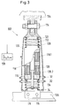
- Fig. 3
- eine weitere Ausführungsform des aktiven Schwingungsminderers mit federnder Bauteil- und Aktuatorabstützung an der Tragstruktur.
- Der in Fig. 1 gezeigte Schwingungsminderer 2 ist zwischen einem in Pfeilrichtung A periodisch belasteten Bauteil 4, etwa dem Hauptgetriebe eines Hubschrauber-Rotorsystems, und einer Tragstruktur 6, also z.B. der Hubschrauberzelle, angeordnet und enthält als Hauptbestandteile ein in Richtung A der dynamischen Belastungen freischwingendes Federpendel 8 in Kombination mit einem das Federpendel 8 fremdkrafterregenden, elektrisch steuerbaren Aktuator 10, die in einem gemeinsamen Gehäuse 12 untergebracht sind, welches den bauteilseitigen Befestigungspunkt 14 im wesentlichen starr mit dem zellenseitigen Befestigungspunkt 16 des Schwingungsminderers 2 verbindet.
- Die Federpendel-Aktuator-Kombination 8, 10 besteht bei dem gezeigten Ausführungsbeispiel aus einer doppelt wirkenden Magnetspulenanordnung 18, deren Magnetspule 20 die linear über Federelemente 22, 24 frei schwingungsfähig am Gehäuse 12 gelagerte Pendelmasse des Federpendels 8 bildet, während der Anker 26 der Magnetspulenordnung 18 fest mit dem Gehäuse 12 verbunden ist.
- Die periodische Erregerkraft am bauteilseitigen Befestigungspunkt 14 führt zu harmonischen Eigenschwingungen des aus der Magnetspule 20 und den Federn 22, 24 bestehenden Federpendels 8. Zusätzlich werden durch phasenkonforme, elektrische Fremdkrafterregung der Magnetspule 20 genau gesteuerte dynamische Wechselkräfte erzeugt, die die Spulenträgheitskraft verstärken und so die bauteilseitigen Erregerkräfte auf dem Wege einer Tilgung oder Isolation vom zellenseitigen Befestigungspunkt 16 fernhalten. Das Übertragungsverhalten des Systems ist abhängig von den Auslegungsparametern, insbesondere der Federcharakteristik der Federelemente 22, 24, der Masse der Magnetspule 20, der Größe der bauteilseitig einwirkenden Erregerkräfte, der Masse der Tragstruktur 6 und des schwingenden Bauteils 4 sowie der Amplitude der magnetischen Wechselkraft. Durch entsprechende Wahl der Auslegungsparameter wird mit einer, bezogen auf die bauteilseitige Erregerkraft, kleinen Pendel-(Spulen-)Masse ein hoher Vibrationsunterdrückungsgrad über einen breiten Frequenzbereich erhalten, wie dies nachfolgend im einzelnen anhand der Fig. 2 erläutert wird, die die Übertragungsfunktion der Auslenkungsamplitude am zellenseitigen Befestigungspunkt 16 für verschieden große Magnetkraftamplituden im Frequenzdiagramm auf der Grundlage eines hubschraubertypischen Datensatzes mit einer Spulenmasse mS = 3,5 kg und einer bauteilseitigen Erregerkraft FR = 500 N zeigt.
- Die Kurve a entspricht dem Eigenschwingungsverhalten des Schwingungsminderers 2 ohne Magnetkrafterregung des Federpendels 8. Dabei ergibt sich bei einer singulären Erregerfrequenz von annähernd 23 Hz zwar rein theoretisch eine Antiresonarz, die jedoch wegen der gewählten Massenverhältnisse technisch nicht nutzbar ist. Der Einfluß der Magnetkrafterregung auf das Systemverhalten ist, gestaffelt nach zunehmend größerer Magnetkraftamplitude, aus den Kurven b, c und d ersichtlich. Man erkennt, daß der Schwingungsminderer 2 nunmehr ein ausgeprägtes Antiresonanzverhalten aufweist, wobei die Lage der Antiresonanzstelle von der Kraftamplitude des Magnetkraftaktuators 10 abhängt. Ferner ist ersichtlich, daß die Antiresonanzwirkung nicht auf eine singuläre Erregerfrequenz beschränkt ist sondern sich über einen breiten Frequenzbereich erstreckt, in welchem die Kurven b, c und d deutlich unterhalb der magnetkraftfreien Vergleichskurve a verlaufen und somit eine signifikante Schwingungsreduktion vorhanden ist.
- Zwischen der Magnetkraftamplitude FM, und der Antiresonanzfrequenz ωA, besteht folgende Beziehung

- Hierin bedeuten
- FM [N]
- = Magnetkraft
- FR [N]
- = bauteilseitige Erregerkraft
- k22, k24 [N/mm]
- = Federkonstanten der Federn 22, 24
- ωA [Hz]
- = Antiresonanzfrequenz
- mS [kg]
- = Masse der Magnetspule 20
- Auf der Basis dieser Abstimmgleichung läßt sich die Antiresonanzstelle des Schwingungsminderers 2 durch Änderung des Kraftverhältnisses FM/FR auf eine gewünsche Frequenz verschieben. So wandert die Antiresonanzstelle bei dem zugrundeliegenden Berechnungsbeispiel von ca. 24 Hz (Kurve b) auf ca. 27 Hz (Kurve d), wenn das Kraftverhältnis FM/FR von 0,1 auf 0,3 erhöht wird.
- Bei Rotorsystemen wird die Antiresonanzfrequenz im allgemeinen auf die erste blattzahlharmonische Rotorerregung, also bei einem Vierblattrotor auf 4 Ω eingestellt. Für moderne Hubschrauber, die mit einer variablen Rotordrehzahl arbeiten, ist es ferner auf der Basis der obigen Abstimmgleichung möglich, die Antiresonanzstelle des Schwingungsminderers 2 automatisch an die Drehzahlvariationen des Rotors anzupassen.
- Zu diesem Zweck ist dem Schwingungsminderer 2 gemäß Fig. 1 eine Steuerstufe 28 einschließlich eines Sensors 30, etwa in Form eines Piezoelementes, zugeordnet, welches zusätzlich zur Amplitude auch die Frequenz der rotorseitigen Erregerkraft FR mißt. In der Steuerstufe 28 wird der Erregerstrom für die beiden Spulenhälften 20.1 und 20.2 mit Hilfe der Abstimmgleichung oder anhand eines Datenkennfeldes so variiert, daß sich die Antiresonanzstelle des Schwingungsminderers 2 an die Rotorerregerfrequenz anpaßt.
- Der Schwingungsminderer gemäß Fig. 3, bei dem die dem ersten Ausführungsbeispiel entsprechenden Bauelemente durch ein um 100 erhöhtes Bezugszeichen gekennzeichnet sind, unterscheidet sich von diesem in erster Linie dadurch, daß das Gehäuse 112 in Richtung der dynamischen Bauteilbelastungen federelastisch (bei 32) ausgebildet und der Anker 126 des Magnetkraftaktuators 110 ebenfalls elastisch, nämlich über ein Tellerfederelement 34, am Gehäuse 112 abgestützt ist. Hierdurch wird die Anzahl der Freiheitsgrade des Systems erhöht, so daß sich die Übertragungsfunktion der Auslenkungsamplituden noch weiter variieren läßt und es durch entsprechende Wahl der Auslegungsparameter sogar möglich ist, ohne Änderung des Magnet-/Erregeerkraftverhältnisses, FM/FR, mehrere diskrete Antiresonanzstellen in einem vorgewählten, gegenseitigen Frequenzabstand zu erzielen, also etwa zusätzlich zu der Antiresonanz bei der ersten, blattzahlharmonischen Rotorerregung (4 Ω) eine weitere Antiresonanzstelle bei der zweiten Blattzahlharmonischen (8 Ω). Durch eine derartige mehrfrequente Auslegung des Schwingungsminderers 102 wird eine hochgradige Reduzierung von hubschrauberspezifischen Vibrationen gewährleistet. Auch bei diesem Ausführungsbeispiel wird die Magnetkrafterregung wiederum durch eine Steuereinheit 128 entweder im Sinne eines konstanten Kraftverhältnisses FM/FR oder aber für variable Rotordrehzahlen und damit Erregerfrequenzen im Sinne einer erregerfrequenzabhängigen Magnetkraftamplitude auf der Basis einer unter Berücksichtigung der federnden Gehäuseabstützung modifizierten Abstimmgleichung reguliert. Im übrigen ist die Bau- und Funktionsweise des Schwingungsminderers 102 die gleiche wie beim ersten Ausführungsbeispiel.
Claims (9)
- Aktiver Schwingungsminderer zum Reduzieren der Schwingungsübertragung von einem dynamisch belasteten Bauteil (4; 104) an eine dieses abstützende Tragstruktur (6; 106), bestehend aus- einem durch die dynamischen Belastungen erregten, frei schwingend zwischen Bauteil und Tragstruktur gelagerten Federpendel (8; 108) und- einem schwingungskonform zum Federpendel aktivierten und dieses mit einer von der Frequenz und Höhe der dynamischen Belastungen (FR) abhängigen Kraftamplitude (FM) in Schwingungsrichtung beaufschlagenden Aktuator (10; 110).
- Schwingungsminderer nach Anspruch 1,
mit einem die dynamischen Bauteilbelastungen (FR) aufnehmenden Seilsor (30) und einer die Kraftamplitude (FM) des Aktuators (10) in Abhängigkeit von der dynamischen Belastungsamplitude und -frequenz des Bauteils (4) veränderlich einstellenden Steuerstufe (28). - Schwingungsminderer nach Anspruch 2,
wobei als Sensor (30) ein auf die dynamischen Bauteilbelastungen (FR) ansprechendes Piezoelement vorgesehen ist. - Schwingungsminderer nach einem der vorhergehenden Ansprüche,
mit einer federnden Abstützung (32) des Bauteils (104) an der Tragstruktur (106). - Schwingungsminderer nach einem der vorhergehenden Ansprüche,
mit einer linear zwischen Bauteil (4; 104) und Tragstruktur (6; 106) frei federnd gelagerten Pendelmasse (20; 120). - Schwingungsminderer nach einem der vorhergehenden Ansprüche,
wobei die Reaktionskraft des Aktuators (10;110) an der Tragstruktur (6; 106) abgestützt ist. - Schwingungsminderer nach einem der vorhergehenden Ansprüche,
wobei der Aktuator (110) federnd (bei 34) an der Tragstruktur (106) oder den, Bauteil (104) abgestützt ist. - Schwingungsminderer nach einem der vorhergehenden Ansprüche,
mit einer elektrisch gesteuerten Magnetspulenanordnung (18; 118), deren Magnetspule (20; 120) als Pendelmasse vorgesehen und deren Anker (26; 126) am Bauteil (4; 104) oder der Tragstruktur (6; 106) abgestützt ist. - Schwingungsminderer nach Anspruch 8,
mit einer doppelt wirkenden Magnetspulenanordnung (18; 118).
Applications Claiming Priority (2)
| Application Number | Priority Date | Filing Date | Title |
|---|---|---|---|
| DE19621700 | 1996-05-30 | ||
| DE19621700A DE19621700C2 (de) | 1996-05-30 | 1996-05-30 | Aktiver Schwingungsminderer |
Publications (3)
| Publication Number | Publication Date |
|---|---|
| EP0811784A2 true EP0811784A2 (de) | 1997-12-10 |
| EP0811784A3 EP0811784A3 (de) | 1999-09-22 |
| EP0811784B1 EP0811784B1 (de) | 2002-09-18 |
Family
ID=7795680
Family Applications (1)
| Application Number | Title | Priority Date | Filing Date |
|---|---|---|---|
| EP97107426A Expired - Lifetime EP0811784B1 (de) | 1996-05-30 | 1997-05-06 | Aktiver Schwingungsdämpfer |
Country Status (2)
| Country | Link |
|---|---|
| EP (1) | EP0811784B1 (de) |
| DE (2) | DE19621700C2 (de) |
Cited By (7)
| Publication number | Priority date | Publication date | Assignee | Title |
|---|---|---|---|---|
| EP1013962A3 (de) * | 1998-12-23 | 2003-01-15 | Carl Freudenberg KG | Aktiver Schwingungstilger |
| EP1201959A3 (de) * | 2000-10-26 | 2003-08-20 | Robert Bosch Gmbh | Vorrichtung zum Dämpfen der Schwingung eines schwingfähig gelagerten Aggregats |
| DE10214325A1 (de) * | 2002-03-28 | 2003-10-16 | Zf Lemfoerder Metallwaren Ag | Verfahren zum Betreiben eines Hydrolagers und hierfür ausgebildetes Lager |
| FR2860564A1 (fr) * | 2003-10-01 | 2005-04-08 | Hutchinson | Systeme d'amortissement de vibrations |
| EP1932693A4 (de) * | 2005-10-07 | 2009-09-16 | Toyota Motor Co Ltd | Elektromagnetische stossdämpfung für fahrzeug |
| US20180156306A1 (en) * | 2016-12-02 | 2018-06-07 | National Research Council Of Canada | Compact vibration reducing human support |
| EP3750801A1 (de) * | 2019-06-13 | 2020-12-16 | LEONARDO S.p.A. | Rotor für ein schwebefähiges flugzeug |
Families Citing this family (18)
| Publication number | Priority date | Publication date | Assignee | Title |
|---|---|---|---|---|
| FR2765647B1 (fr) * | 1997-07-07 | 2002-01-11 | Jacques Clausin | Reducteur de vibrations monoaxe accorde a bande large et de grande legerete |
| DE10043128C2 (de) | 2000-08-31 | 2003-05-08 | Univ Hannover | Tilgervorrichtung zur Absorption einer unerwünschten Erregung |
| FR2825769B1 (fr) * | 2001-06-06 | 2004-08-27 | Vibrachoc Sa | Dispositif d'amortissement de vibrations |
| DE10321436B8 (de) * | 2003-05-09 | 2005-04-14 | Universität des Saarlandes | Vorrichtung zur Erzeugung von Kräften |
| KR20090076903A (ko) | 2006-10-12 | 2009-07-13 | 벨 헬리콥터 텍스트론 인크. | 진동 완화 강성 장착 파일런 |
| JP5278202B2 (ja) * | 2009-07-02 | 2013-09-04 | 日産自動車株式会社 | 振動低減装置 |
| EP2558649B1 (de) | 2010-04-16 | 2014-11-19 | Ammann Schweiz AG | Anordnung zur bereitstellung einer pulsierenden druckkraft |
| US9457635B2 (en) * | 2010-09-23 | 2016-10-04 | Renton Coil Spring Company | Magnetic damper |
| FR2968053B1 (fr) * | 2010-11-26 | 2013-08-23 | Hutchinson | Dispositif de controle vibratoire actif, vehicule comportant un tel dispositif et chape active pour un tel dispositif. |
| FR2969236B1 (fr) * | 2010-12-16 | 2012-12-28 | Renault Sa | Bielle de liaison entre un groupe moto propulseur de vehicule automobile et un element structurel du vehicule automobile |
| DE102014110753A1 (de) | 2014-07-29 | 2016-02-04 | Airbus Defence and Space GmbH | Kraftgenerator mit durch elektronisches Bauelement gebildeter Inertialmasse sowie Ansteuerschaltung hierfür |
| CN105370780A (zh) * | 2015-10-30 | 2016-03-02 | 合肥工业大学 | 一种可以进行能量收集的减振器 |
| CN105909725B (zh) * | 2016-04-14 | 2018-02-02 | 华中科技大学 | 一种三自由度微振动抑制平台及其控制方法 |
| WO2019241882A1 (en) | 2018-06-19 | 2019-12-26 | Mark Elias | Apparatus and method for suppressing oscillations |
| US11420248B2 (en) | 2018-12-12 | 2022-08-23 | The Boeing Company | Impact-compensating bucking bar |
| CN110259241B (zh) * | 2019-06-19 | 2020-12-04 | 同济大学 | 自适应变刚度半主动变阻尼的智能调谐质量阻尼器 |
| US11150047B2 (en) * | 2019-07-25 | 2021-10-19 | The Boeing Company | Firearm incorporating recoil reduction |
| CN110886810B (zh) * | 2019-11-22 | 2021-07-30 | 武汉理工大学 | 轴系横向振动电磁式主动控制装置 |
Family Cites Families (7)
| Publication number | Priority date | Publication date | Assignee | Title |
|---|---|---|---|---|
| US4610420A (en) * | 1984-02-16 | 1986-09-09 | Nissan Motor Company, Limited | Apparatus for mounting power unit |
| JPS63306183A (ja) * | 1987-06-03 | 1988-12-14 | 株式会社日立製作所 | 振動防止装置 |
| DE3902603C2 (de) * | 1989-01-28 | 1994-01-27 | Continental Ag | Elastische Lagerung, insbesondere Kraftfahrzeug-Motorlager |
| SE466796B (sv) * | 1990-08-10 | 1992-04-06 | Saab Scania Ab | Fjaedersystem med foerbaettrad resonansdaempning och ett foerfarande foer reglering av fjaedringssystemet |
| FR2678032B1 (fr) * | 1991-06-18 | 1993-10-01 | Aerospatiale Ste Nationale Indle | Dispositif de liaison elastique entre deux pieces, et aeronef a voilure tournante comportant ledit dispositif. |
| DE19517630C2 (de) * | 1995-05-13 | 1997-10-09 | Metzeler Gimetall Ag | Aktiver Schwingungstilger |
| DE19532039A1 (de) * | 1995-08-31 | 1997-03-06 | Porsche Ag | Vorrichtung zum Bedämpfen von Karosserieschwingungen |
-
1996
- 1996-05-30 DE DE19621700A patent/DE19621700C2/de not_active Expired - Fee Related
-
1997
- 1997-05-06 EP EP97107426A patent/EP0811784B1/de not_active Expired - Lifetime
- 1997-05-06 DE DE59708233T patent/DE59708233D1/de not_active Expired - Lifetime
Cited By (11)
| Publication number | Priority date | Publication date | Assignee | Title |
|---|---|---|---|---|
| EP1013962A3 (de) * | 1998-12-23 | 2003-01-15 | Carl Freudenberg KG | Aktiver Schwingungstilger |
| EP1201959A3 (de) * | 2000-10-26 | 2003-08-20 | Robert Bosch Gmbh | Vorrichtung zum Dämpfen der Schwingung eines schwingfähig gelagerten Aggregats |
| DE10214325A1 (de) * | 2002-03-28 | 2003-10-16 | Zf Lemfoerder Metallwaren Ag | Verfahren zum Betreiben eines Hydrolagers und hierfür ausgebildetes Lager |
| FR2860564A1 (fr) * | 2003-10-01 | 2005-04-08 | Hutchinson | Systeme d'amortissement de vibrations |
| EP1932693A4 (de) * | 2005-10-07 | 2009-09-16 | Toyota Motor Co Ltd | Elektromagnetische stossdämpfung für fahrzeug |
| US8127900B2 (en) | 2005-10-07 | 2012-03-06 | Toyota Jidosha Kabushiki Kaisha | Electromagnetic shock absorber for vehicle |
| US20180156306A1 (en) * | 2016-12-02 | 2018-06-07 | National Research Council Of Canada | Compact vibration reducing human support |
| US10774898B2 (en) * | 2016-12-02 | 2020-09-15 | National Research Council Of Canada | Compact vibration reducing human support |
| EP3750801A1 (de) * | 2019-06-13 | 2020-12-16 | LEONARDO S.p.A. | Rotor für ein schwebefähiges flugzeug |
| WO2020250063A1 (en) * | 2019-06-13 | 2020-12-17 | Leonardo S.P.A. | Rotor for a hover-capable aircraft |
| US11866159B2 (en) | 2019-06-13 | 2024-01-09 | Leonardo S.P.A. | Rotor for a hover-capable aircraft |
Also Published As
| Publication number | Publication date |
|---|---|
| DE19621700A1 (de) | 1997-12-04 |
| EP0811784B1 (de) | 2002-09-18 |
| DE19621700C2 (de) | 2001-09-27 |
| EP0811784A3 (de) | 1999-09-22 |
| DE59708233D1 (de) | 2002-10-24 |
Similar Documents
| Publication | Publication Date | Title |
|---|---|---|
| DE19621700C2 (de) | Aktiver Schwingungsminderer | |
| EP0580272B1 (de) | Schwingungsdämpfer | |
| EP0924960B1 (de) | Aufhängung für Schallwiedergabeanordnungen nach dem Biegewellenprinzip | |
| DE69231190T2 (de) | Aktives panel mit hoher übertragungsdämpfung | |
| DE10116166C2 (de) | Akustisch aktive Scheibe | |
| EP3227579B1 (de) | Adaptiver pendeltilger mit vertikaler federvorrichtung | |
| DE69937858T2 (de) | Verfahren und Vorrichtung zur Messung von Vibrationswellen | |
| DE3137697A1 (de) | Elektromagnetischer foerderer | |
| DE60028654T2 (de) | Resonante Vorrichtung wie Schläger oder Klopfer | |
| EP1927782A1 (de) | Aktiver Tilger | |
| DE3540431A1 (de) | Vorrichtung zur minderung von vibrationen | |
| DE102011101271A1 (de) | Turmschwingungstilger und Turm mit einem Turmschwingungstilger | |
| DE10145145A1 (de) | Anordnung zur Schwingungsdämpfung | |
| DE112016000199T5 (de) | Stromerzeuger | |
| EP0054723B1 (de) | Akustischer Oberflächenwellenresonator | |
| EP3576974B1 (de) | Bedieneinheit für ein gerät, insbesondere für eine fahrzeugkomponente | |
| DE3902605A1 (de) | Elastische lagerung, insbesondere kraftfahrzeug-motorlager | |
| EP2993372A1 (de) | Kraftgenerator mit durch elektronisches bauelement gebildeter inertialmasse sowie ansteuerschaltung hierfür | |
| EP2598770A1 (de) | Schwingungsabsorber zur dämpfung mechanischer schwingungen | |
| DE102011076555A1 (de) | Mikromechanisches Bauelement mit einer Dämpfungseinrichtung | |
| EP0886079A2 (de) | Verfahren und Vorrichtung zur Dämpfung von Schwingungen mit einem Schwingungstilger | |
| EP0464598B1 (de) | Elastisches Motorlager | |
| DE102007052494A1 (de) | Piezoelektrische Antriebsvorrichtung | |
| DE1953028U (de) | Schwingungstilger zur daempfung mechanischer schwingungen eines bauteiles oder gehaeuses, vorzugsweise eines transformatorgehaeuses. | |
| EP0122873A2 (de) | Elastisches Lagerungselement zur schwingungsisolierenden und körperschallisolierenden Aufstellung von Aggregaten |
Legal Events
| Date | Code | Title | Description |
|---|---|---|---|
| PUAI | Public reference made under article 153(3) epc to a published international application that has entered the european phase |
Free format text: ORIGINAL CODE: 0009012 |
|
| AK | Designated contracting states |
Kind code of ref document: A2 Designated state(s): DE FR GB IT |
|
| 17P | Request for examination filed |
Effective date: 19971219 |
|
| PUAL | Search report despatched |
Free format text: ORIGINAL CODE: 0009013 |
|
| AK | Designated contracting states |
Kind code of ref document: A3 Designated state(s): DE FR GB IT |
|
| RAP1 | Party data changed (applicant data changed or rights of an application transferred) |
Owner name: EUROCOPTER DEUTSCHLAND GMBH |
|
| 17Q | First examination report despatched |
Effective date: 20010322 |
|
| GRAG | Despatch of communication of intention to grant |
Free format text: ORIGINAL CODE: EPIDOS AGRA |
|
| GRAG | Despatch of communication of intention to grant |
Free format text: ORIGINAL CODE: EPIDOS AGRA |
|
| GRAH | Despatch of communication of intention to grant a patent |
Free format text: ORIGINAL CODE: EPIDOS IGRA |
|
| GRAH | Despatch of communication of intention to grant a patent |
Free format text: ORIGINAL CODE: EPIDOS IGRA |
|
| GRAA | (expected) grant |
Free format text: ORIGINAL CODE: 0009210 |
|
| AK | Designated contracting states |
Kind code of ref document: B1 Designated state(s): DE FR GB IT |
|
| REG | Reference to a national code |
Ref country code: GB Ref legal event code: FG4D Free format text: NOT ENGLISH |
|
| REF | Corresponds to: |
Ref document number: 59708233 Country of ref document: DE Date of ref document: 20021024 |
|
| GBT | Gb: translation of ep patent filed (gb section 77(6)(a)/1977) |
Effective date: 20030107 |
|
| ET | Fr: translation filed | ||
| PLBE | No opposition filed within time limit |
Free format text: ORIGINAL CODE: 0009261 |
|
| STAA | Information on the status of an ep patent application or granted ep patent |
Free format text: STATUS: NO OPPOSITION FILED WITHIN TIME LIMIT |
|
| 26N | No opposition filed |
Effective date: 20030619 |
|
| PGFP | Annual fee paid to national office [announced via postgrant information from national office to epo] |
Ref country code: FR Payment date: 20040512 Year of fee payment: 8 |
|
| PG25 | Lapsed in a contracting state [announced via postgrant information from national office to epo] |
Ref country code: FR Free format text: LAPSE BECAUSE OF NON-PAYMENT OF DUE FEES Effective date: 20060131 |
|
| REG | Reference to a national code |
Ref country code: FR Ref legal event code: ST Effective date: 20060131 |
|
| PGFP | Annual fee paid to national office [announced via postgrant information from national office to epo] |
Ref country code: GB Payment date: 20110503 Year of fee payment: 15 |
|
| PGFP | Annual fee paid to national office [announced via postgrant information from national office to epo] |
Ref country code: DE Payment date: 20110505 Year of fee payment: 15 Ref country code: IT Payment date: 20110430 Year of fee payment: 15 |
|
| GBPC | Gb: european patent ceased through non-payment of renewal fee |
Effective date: 20120506 |
|
| PG25 | Lapsed in a contracting state [announced via postgrant information from national office to epo] |
Ref country code: IT Free format text: LAPSE BECAUSE OF NON-PAYMENT OF DUE FEES Effective date: 20120506 |
|
| REG | Reference to a national code |
Ref country code: DE Ref legal event code: R119 Ref document number: 59708233 Country of ref document: DE Effective date: 20121201 |
|
| PG25 | Lapsed in a contracting state [announced via postgrant information from national office to epo] |
Ref country code: GB Free format text: LAPSE BECAUSE OF NON-PAYMENT OF DUE FEES Effective date: 20120506 |
|
| PG25 | Lapsed in a contracting state [announced via postgrant information from national office to epo] |
Ref country code: DE Free format text: LAPSE BECAUSE OF NON-PAYMENT OF DUE FEES Effective date: 20121201 |