EP0811785A2 - Manchon à amortissement hydraulique - Google Patents
Manchon à amortissement hydraulique Download PDFInfo
- Publication number
- EP0811785A2 EP0811785A2 EP97102613A EP97102613A EP0811785A2 EP 0811785 A2 EP0811785 A2 EP 0811785A2 EP 97102613 A EP97102613 A EP 97102613A EP 97102613 A EP97102613 A EP 97102613A EP 0811785 A2 EP0811785 A2 EP 0811785A2
- Authority
- EP
- European Patent Office
- Prior art keywords
- rubber spring
- sleeve rubber
- support body
- compensation chamber
- chamber
- Prior art date
- Legal status (The legal status is an assumption and is not a legal conclusion. Google has not performed a legal analysis and makes no representation as to the accuracy of the status listed.)
- Granted
Links
Images



Classifications
-
- F—MECHANICAL ENGINEERING; LIGHTING; HEATING; WEAPONS; BLASTING
- F16—ENGINEERING ELEMENTS AND UNITS; GENERAL MEASURES FOR PRODUCING AND MAINTAINING EFFECTIVE FUNCTIONING OF MACHINES OR INSTALLATIONS; THERMAL INSULATION IN GENERAL
- F16F—SPRINGS; SHOCK-ABSORBERS; MEANS FOR DAMPING VIBRATION
- F16F13/00—Units comprising springs of the non-fluid type as well as vibration-dampers, shock-absorbers, or fluid springs
- F16F13/04—Units comprising springs of the non-fluid type as well as vibration-dampers, shock-absorbers, or fluid springs comprising both a plastics spring and a damper, e.g. a friction damper
- F16F13/06—Units comprising springs of the non-fluid type as well as vibration-dampers, shock-absorbers, or fluid springs comprising both a plastics spring and a damper, e.g. a friction damper the damper being a fluid damper, e.g. the plastics spring not forming a part of the wall of the fluid chamber of the damper
- F16F13/08—Units comprising springs of the non-fluid type as well as vibration-dampers, shock-absorbers, or fluid springs comprising both a plastics spring and a damper, e.g. a friction damper the damper being a fluid damper, e.g. the plastics spring not forming a part of the wall of the fluid chamber of the damper the plastics spring forming at least a part of the wall of the fluid chamber of the damper
- F16F13/14—Units of the bushing type, i.e. loaded predominantly radially
Definitions
- the invention relates to a hydraulically damping sleeve rubber spring with an inner support body which is surrounded by an outer support body at a radial distance, wherein a spring body made of elastomeric material is arranged in the gap formed by the distance, the outer support body and the spring body delimiting at least one working chamber which is connected to at least one first compensation chamber in a liquid-conducting manner by at least one damping channel.
- Such a sleeve rubber spring is known from DE 38 20 805 A1.
- the sleeve rubber spring is provided for mounting an engine of a motor vehicle on a motor vehicle body.
- the spring body is arranged between the inner support body and the outer support body, the spring body having a cavity above the load introduction onto the inner support body, and in the direction of the load introduction the working chamber and the compensation chamber, which are connected to one another by the damping channel.
- the damping channel is a component of a partition wall which separates the working chamber from the first compensation chamber, a recess being provided within the partition wall and inside the recess for insulation of higher frequency, small-amplitude vibrations a vibration plate is arranged to reciprocate in the direction of the vibrations introduced.
- the previously known sleeve rubber spring consists of a large number of individual parts, which is unsatisfactory from an economic and production point of view.
- the invention has for its object to develop a sleeve rubber spring of the type mentioned in such a way that there is a significantly simplified structure and better performance properties with respect to the isolation / damping of vibrations and that the bearing causes a reduction in the dynamic spring rate in at least two frequency ranges.
- the sleeve rubber spring should be easy to adapt to the particular circumstances of the application by simple design changes.
- the first compensation chamber viewed in cross section, is delimited by the outer support body and a rubber-elastic expansion wall and that at least one second compensation chamber is arranged in the first compensation chamber and is connected to the working chamber by a connecting channel.
- the advantage here is that the sleeve rubber spring has a simple structure with few parts and is therefore simple and inexpensive to manufacture in terms of production technology and economy.
- the entire sleeve rubber spring consists of only two parts to be assembled with one another, the second part being formed by the inner support body and the spring body connected to the inner support body, the unit consisting of the spring body and the inner support body with the outer support body that forms the first part.
- the inner support body When low-frequency, large-amplitude vibrations are introduced into the sleeve rubber spring, the inner support body, relative to the outer support body, is displaced radially in such a way that a part of the liquid contained in the work chamber is conveyed through the damping channel into the first compensation chamber by reducing the volume of the work chamber. The volume of liquid displaced from the working chamber is received in the first compensation chamber and, when the two support bodies return to their starting position, are released into the working chamber again.
- the sleeve rubber spring can be matched to low-frequency, large-amplitude vibrations by varying the length and / or the cross section of the damping channel.
- the dynamic spring rate in the event of liquid displacements is reduced from the working chamber through the damping channel into the first compensation chamber.
- the dynamic spring rate is reduced a second time in a comparatively higher-frequency range by the vibration excitation of the liquid components within the second compensation chamber.
- the third drop in dynamic spring rate at a frequency that is even higher is, as the frequencies in the range of the first and second reduction, takes place through the excitation of liquid components in the two subchambers of the first compensation chamber.
- the second compensation chamber can have a substantially kidney-shaped cross-section and extend in the circumferential direction of the sleeve rubber spring and can be delimited on all sides by membrane-like boundary walls made of rubber-elastic material, the boundary walls being associated with the outer support body and the inflatable wall adjacent to each other at a radial distance.
- the radial distance with which the boundary walls are assigned to the outer support body and the inflatable wall is dimensioned such that when low-frequency, large-amplitude vibrations are introduced, the second compensation chamber is inflated.
- the second compensation chamber can be inflated, for example, until the boundary walls are supported in the radial direction on the outside on the outer support body and in the radial direction on the inside on the inflatable wall of the first compensation chamber.
- the boundary walls can, for example, be provided with reinforcement, wherein the reinforcement can be arranged on the side of the boundary walls facing the first compensation chamber, within the boundary walls or within the second compensation chamber.
- the second compensation chamber is preferably pocket-shaped in the axial direction and extends parallel to the longitudinal axis of the sleeve rubber spring into the first compensation chamber.
- the extension of the second compensation chamber in the axial direction can be the particular circumstances of the application can be easily adjusted. If, for example, the largest possible volume of the second compensation chamber is desired and its extent in the circumferential direction must not exceed a comparatively small extent, there is the possibility that the second compensation chamber extends in the axial direction over almost the entire axial width of the sleeve rubber spring.
- the boundary walls of the second compensation chamber are completely enclosed by the damping liquid which is located in the first compensation chamber.
- the spring body, the inflatable wall and the boundary wall can be integrally merged and made of the same material.
- the handling of the individual parts for mounting the sleeve rubber spring is particularly easy.
- a separate sealing of the parts made of elastomeric material against each other is unnecessary.
- a secure seal of the working chamber and the two compensation chambers in the direction of the environment is guaranteed even during a long period of use.
- three second compensation chambers can be arranged evenly distributed in the circumferential direction within the first compensation chamber.
- the second compensation chambers are preferably formed with boundary walls of expanding elasticity that differ from one another and / or have volumes that differ from one another.
- the somewhat more complicated design of the sleeve rubber spring is contrasted by further improved usage properties with regard to the optimal adaptation of the usage properties to the respective application. Due to the increased number of second compensation chambers, in addition to the at least two reductions dynamic spring rate, which are required anyway, further reductions in the dynamic spring rate can be achieved in other frequency ranges.
- the first compensation chamber can consist of at least two partial chambers which are connected in a liquid-conducting manner by means of a throttle opening.
- the throttle opening preferably extends within the first compensation chamber in the circumferential direction, the damping channel preferably opening into the partial chamber of the first compensation chamber in which at least one second compensation chamber is arranged. Due to the liquid displacement between the two subchambers of the first compensation chamber through the throttle opening, a further, d. H. third reduction of the dynamic spring rate causes.
- the throttle opening can, for example, be limited only in the region of the throttle opening by the inner peripheral surface of the outer support body and the partial thickening of the inflatable wall. Depending on the opening cross-section of the throttle opening and / or its length, the damping behavior of the sleeve rubber spring can be influenced.
- the compensation chamber has an essentially trapezoidal cross section. Due to the trapezoidal cross section of the working chamber, the first compensation chamber has a comparative view in the circumferential direction of the sleeve rubber spring large expansion, so that, if necessary, a plurality of second compensation chambers can be provided and / or a plurality of sub-chambers which are connected to one another by throttle openings.
- the inner support body can be completely enclosed on the circumferential side by the spring body.
- the advantage here is that no additional rust protection measures are required for the inner support body.
- the sheathing of the inner support body by the spring body results in an excellent connection between the two parts.
- the inner support body preferably has an essentially trapezoidal cross section, such that the support webs of the spring body touch the peripheral surface of the inner support body at an angle of 45 to 90 °.
- the angle is preferably 60 to 80 °. It should be ensured that the angle is always less than 90 °.
- the inner support body On the side facing away from the working chamber, the inner support body can have a stop buffer formed in one piece with the spring body. This prevents harmful tensile stresses occurring within the support webs in the event of extreme deflection movements of the inner support body in relation to the outer support body.
- the two support webs, the inner one arranged between them Support body as well as the stop buffer arranged on the side of the inner support body facing away from the support webs as a whole are roof-shaped.
- the low-part construction of the sleeve rubber spring is not adversely affected by the stop buffer, since it is connected in one piece to the spring body and thereby also in one piece with the inflatable wall of the first compensation chamber and the boundary walls of the second compensation chamber.
- the inner support body can have an open anti-rotation device at least on the face side in the axial direction. Preference is given to using anti-rotation devices on both sides in the axial direction.
- the anti-rotation devices are preferably designed as blind holes and serve to ensure that the correct mounting is ensured when the inner support body is attached to a suitable counterpart.
- the anti-rotation devices are preferably arranged in radial projections which extend radially in the direction of the working chamber, a recess extending parallel to the longitudinal axis of the sleeve rubber spring being provided in the axial direction between the radial projections.
- the advantage here is that through the recess in the inner support body and because the recess is filled with elastomeric material of the spring body, the radial flexibility of the inner support body relative to the outer support body is increased transversely to the main direction of the vibrations introduced.
- the anti-rotation devices provided have only a negligible influence on the usage properties of the sleeve rubber spring, although the anti-rotation devices result in a significant simplification in the assembly of the sleeve rubber spring.
- the axial / radial stiffness in the secondary directions can be increased if this is necessary for an application.
- the spring body and a window tube made of tough, preferably metallic material form a unit and are connected to one another by vulcanization.
- the window tube which is almost completely enclosed by the elastomeric material of the spring body, brings about a reliable seal with respect to the surroundings of the sleeve rubber spring in that the unit with elastic pretension is arranged within the outer support body.
- the outer support body is flanged in the area of one of its two end faces in such a way that the flanged first part forms a stop for the second part to be inserted.
- the second part consists of the inner support body encased on the circumferential side by the elastomeric material of the spring body and the window tube, which is likewise enclosed by the elastomeric material of the spring body, and the expansion walls of the first compensation chamber and the boundary walls of the second compensation chamber, which are formed in one piece with the spring body.
- the second part is introduced into the first part, which is formed by the outer support body, in a fluid bath filled with damping liquid, the second end face of the outer support body is flanged, so that the two parts that make up the sleeve rubber spring are captive and liquid-tight are interconnected.
- the assembly of the two parts under fluid ensures that no air cushion forms within the sleeve rubber spring.
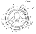
- a sleeve rubber spring 1 which is designed as a single-chamber bearing, and consists of only two parts to be assembled together.
- One of the parts is formed by the outer support body 3, while the other part is formed by a unit 22, which consists of the spring body 5, inflatable wall 9, the boundary walls 12 and the stop buffer 6 and the window tube 21.
- the spring body 5, the inflatable wall 9, the boundary walls 12 and the stop buffer 16 consist of a matching elastomeric material and are integrally formed into one another.
- the outer support body 3 and the spring body 5 delimit a working chamber 6 filled with damping liquid, which is connected in a liquid-conducting manner by at least one damping channel 7 to at least one first equalizing chamber 8, which is also filled with damping liquid and essentially takes up volume without pressure.
- the first compensation chamber 8 extends along the inner circumferential surface of the outer support body 3 and is delimited on the outside by the outer support body 3 in the radial direction and on the inside by the rubber-elastic expansion wall 9.
- a second compensation chamber 10 is arranged within the first compensation chamber 8 and is connected to the working chamber 6 through the connecting channel 11.
- Fig. 1 the different lengths of damping channel 7 and connecting channel 11 is shown schematically.
- the damping channel 7 has a significantly greater length and a significantly larger passage cross section than the connecting channel 11.
- the first equalization chamber 8 consists of two subchambers 8.1, 8.2, the damping channel 7 having a length that is three-quarters in circumference the sleeve rubber spring corresponds and its mouths open on the one hand into the working chamber 6 and on the other hand into the second sub-chamber 8.2.
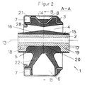
- FIG. 2 shows a longitudinal section through the sleeve rubber spring from FIG. 1 along the line AA.
- the damping channel 7 is shown, which extends around the circumferential direction
- Sleeve rubber spring 1 extends, opens into the working chamber 6 and is limited by the outer support body 3 and the window tube 21.
- the design of the inner support body 2 is clearly visible.
- the inner support body 2 is completely enclosed on the outer peripheral side by the elastomeric material of the spring body and has a stop buffer 16 on the side facing away from the working chamber 6, in order to limit extreme relative displacements of the inner support body 2 with respect to the outer support body 3.
- the inner support body 2 consists of a metallic material and, in the region of its two end faces, has anti-rotation locks 17 in the axial direction, which are designed as blind holes.
- the anti-rotation devices 17 are arranged within radial projections 18, 19, which extend in the direction of the working chamber 6, the recess 20 of the inner support body 2 extending in the axial direction between the radial projections 18, 19. This configuration results in a greater flexibility of the sleeve rubber spring in the direction perpendicular to the plane of the drawing.
- the second compensation chamber 10 arranged in the first compensation chamber 8 has a substantially kidney-shaped cross section and extends in the circumferential direction of the sleeve rubber spring 1.
- the second compensation chamber 10 is delimited on all sides by membrane-like, expandable boundary walls 12 made of rubber-elastic material.
- the second compensation chamber 10 is arranged within the first compensation chamber 8 filled with damping liquid in such a way that its boundary walls 12 are arranged in the radial direction at a distance from the outer support body 3 and the inflatable wall 9 of the first compensation chamber 8.
- the first compensation chamber 8 is formed by two subchambers 8.1, 8.2, which are connected to one another by a throttle opening 14 that extends in the circumferential direction.
- the inner support body 2 has a trapezoidal cross-section, the contact surfaces, each with an imaginary plane 23, 24, which cut through the center of the support webs 5.1, 5.2, limit an angle ⁇ , which in this exemplary embodiment is 65 °.
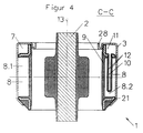
- FIG. 4 shows the section C-C from FIG. 1.
- the second compensation chamber 10 extends parallel to the longitudinal axis 13 of the sleeve rubber spring 1, is pocket-shaped, the ratio of the axial depth of the first compensation chamber 8 to the axial depth of the second compensation chamber 10 should be at most two. In this example, the ratio is 1.2.
- the outer support body 3 is provided radially on the inside with an end stop 28 which extends in the circumferential direction and can be brought into contact with the inner support body 2 in the radial direction in order to limit extreme deflection movements of the inner support body 2 in relation to the outer support body 3.
- the boundary walls 12 can be provided with profiles on the sides facing one another or on the sides facing away from one another, in order to avoid impact noises and / or undesirable overstretching of the elastomeric material when the boundary walls come into contact with one another or with the adjacent inflatable wall and the outer supporting body.
- FIG. 5 shows a diagram in which the dynamic spring rate is plotted against the frequency for the sleeve rubber spring 1 shown in FIGS. 1 to 4.
- the dynamic spring rate can be reduced in three frequency ranges.
- the first frequency range 25 around 4 Hz
- the dynamic spring rate is reduced by the liquid being displaced from the working chamber 6 through the damping channel 7 into the second sub-chamber 8.2 of the first compensation chamber 8.
- the second reduction 26 takes place in the range of 25 Hz in that liquid components in the second Compensation chamber 10 are excited to vibrate.
- the third reduction 27 of the dynamic spring rate takes place in the range around 50 Hz and is achieved in that the liquid column oscillates between the two subchambers 8.1, 8.2 in the throttle opening 14.
- 6 and 7 show further exemplary embodiments of the second compensation chamber 10.
- the boundary walls are separated from one another on the sides facing one another by a first molded part 29.
- the molded part 29 can, for example, consist of a tough, hard polymeric material and prevents the boundary walls 12 from touching the stop if a vacuum occurs within the second compensation chamber 10.
- FIG. 7 shows a second molded part 30 which encloses the boundary walls 12 of the second compensation chamber 10 on the outside like a clamp. This prevents overpressure-related overstretching of the material from which the boundary walls 12 consist leads to damage to the sleeve rubber spring 1. Furthermore, the spring characteristic of the sleeve rubber spring 1 can additionally be adapted to the respective circumstances of the application by means of the second molded part 30.
- the sleeve rubber spring 1 is designed as a single-chamber bearing in FIGS. 1 to 4.
- a sleeve rubber spring 1 is shown, which is designed as a two-chamber bearing.
- the first compensation chamber 8 forms the second chamber in addition to the first working chamber 6 and is delimited by the outer support body 3 and the spring body 5.
- a penetration 31 is provided between the support webs 5.1, 5.2 in the radial direction below the inner support body 2 and extends parallel to the longitudinal axis 13 of the sleeve rubber spring 1.
- the damping channel 7 extends almost over the entire circumference of the sleeve rubber spring 1 from the working chamber 6 into the first compensation chamber 8.
- FIG. 9 shows the section E-E from FIG. 8.
- Both the connecting channel 11 and the damping channel 7 extend almost over the entire circumference of the sleeve rubber spring 1, wherein to form the damping channel 7, the window tube 21 in the region of one of the end boundaries of the sleeve rubber spring 1 has a radially outwardly open, substantially U-shaped groove limited.
- the connecting channel 11 is provided on the end face of the sleeve rubber spring 1 opposite in the axial direction.
- FIGS. 1 to 4 and 8 and 9 The sleeve rubber spring according to the invention from FIGS. 1 to 4 and 8 and 9 are each shown in the production-related, statically unloaded state.
Landscapes
- Engineering & Computer Science (AREA)
- General Engineering & Computer Science (AREA)
- Mechanical Engineering (AREA)
- Combined Devices Of Dampers And Springs (AREA)
Applications Claiming Priority (2)
| Application Number | Priority Date | Filing Date | Title |
|---|---|---|---|
| DE19622248 | 1996-06-04 | ||
| DE19622248A DE19622248C2 (de) | 1996-06-04 | 1996-06-04 | Hydraulisch dämpfende Hülsengummifeder |
Publications (3)
| Publication Number | Publication Date |
|---|---|
| EP0811785A2 true EP0811785A2 (fr) | 1997-12-10 |
| EP0811785A3 EP0811785A3 (fr) | 2000-01-05 |
| EP0811785B1 EP0811785B1 (fr) | 2001-10-17 |
Family
ID=7796019
Family Applications (1)
| Application Number | Title | Priority Date | Filing Date |
|---|---|---|---|
| EP97102613A Expired - Lifetime EP0811785B1 (fr) | 1996-06-04 | 1997-02-19 | Manchon à amortissement hydraulique |
Country Status (5)
| Country | Link |
|---|---|
| US (1) | US6015141A (fr) |
| EP (1) | EP0811785B1 (fr) |
| JP (1) | JP2909046B2 (fr) |
| BR (1) | BR9703443A (fr) |
| DE (2) | DE19622248C2 (fr) |
Cited By (1)
| Publication number | Priority date | Publication date | Assignee | Title |
|---|---|---|---|---|
| EP0945640A3 (fr) * | 1998-03-23 | 2002-02-13 | Tokai Rubber Industries, Ltd. | Isolateur de vibration |
Families Citing this family (10)
| Publication number | Priority date | Publication date | Assignee | Title |
|---|---|---|---|---|
| JP3446668B2 (ja) * | 1998-07-29 | 2003-09-16 | 東海ゴム工業株式会社 | 液体封入式防振装置 |
| JP4018256B2 (ja) * | 1998-09-04 | 2007-12-05 | 山下ゴム株式会社 | 円筒型液封防振装置 |
| FR2814521B1 (fr) * | 2000-09-26 | 2003-06-06 | C F Gomma Barre Thomas | Articulation hydroelastique a comportement dynamique haute frequence |
| US7044455B2 (en) * | 2001-04-27 | 2006-05-16 | Tokai Rubber Industries, Ltd. | Fluid-filled vibration damping device |
| DE10163555A1 (de) | 2001-12-21 | 2003-07-10 | Contitech Vibration Control | Motorlager |
| ITTO20020128A1 (it) * | 2002-02-15 | 2003-08-18 | Gomma C F Spa | Supporto idroelastico, particolarmente per un motore a combustione interna. |
| WO2005015050A2 (fr) * | 2003-08-06 | 2005-02-17 | Freudenberg-Nok General Partnership | Montage du support du groupe propulseur |
| DE102005003052A1 (de) | 2005-01-22 | 2006-08-03 | Carl Freudenberg Kg | Hydrobuchse |
| EP2436946B1 (fr) | 2010-09-29 | 2013-08-21 | Carl Freudenberg KG | Elément de chauffage pour composants à oscillation |
| DE102013209990A1 (de) * | 2013-05-29 | 2014-12-04 | Zf Friedrichshafen Ag | Hydraulisch dämpfendes Gummilager |
Family Cites Families (18)
| Publication number | Priority date | Publication date | Assignee | Title |
|---|---|---|---|---|
| US4826145A (en) * | 1987-01-23 | 1989-05-02 | Dunlop Limited A British Company | Resilient torsion bearing |
| JP2790452B2 (ja) * | 1987-06-19 | 1998-08-27 | 株式会社ブリヂストン | 防振装置 |
| JPS6465344A (en) * | 1987-08-25 | 1989-03-10 | Bridgestone Corp | Vibration isolating device |
| JPH0799186B2 (ja) * | 1987-12-28 | 1995-10-25 | 日産自動車株式会社 | 内外筒型流体封入式パワーユニットマウント |
| JP2793598B2 (ja) * | 1988-08-02 | 1998-09-03 | 株式会社ブリヂストン | 防振装置 |
| FR2650356B1 (fr) * | 1989-07-31 | 1994-05-27 | Hutchinson | Perfectionnements apportes aux man chons antivibratoires hydrauliques |
| FR2655111B1 (fr) * | 1989-11-24 | 1994-05-13 | Hutchinson | Perfectionnements apportes aux manchons antivibratoires hydrauliques. |
| FR2656907B1 (fr) * | 1990-01-09 | 1994-07-01 | Hutchinson | Perfectionnements apportes aux manchons antivibratoires hydrauliques. |
| FR2659712B1 (fr) * | 1990-03-16 | 1992-07-17 | Hutchinson | Perfectionnements apportes aux manchons antivibratoires hydrauliques. |
| DE4015528A1 (de) * | 1990-05-15 | 1991-11-21 | Freudenberg Carl Fa | Gummilager fuer einen kolbenmotor |
| US5397113A (en) * | 1991-02-22 | 1995-03-14 | Bridgestone Corporation | Vibration isolation apparatus |
| DE4137977C2 (de) * | 1991-11-19 | 1995-06-14 | Freudenberg Carl Fa | Mehrkammer-Hydrobuchse |
| DE4242080C1 (de) * | 1992-12-14 | 1994-03-10 | Freudenberg Carl Fa | Buchsenlager |
| DE4222486C2 (de) * | 1992-07-09 | 1994-06-01 | Freudenberg Carl Fa | Hydraulisch dämpfendes Gummilager |
| DE4228842C1 (de) * | 1992-08-29 | 1994-05-05 | Freudenberg Carl Fa | Hydraulisch dämpfendes Gummilager |
| US5286011A (en) * | 1992-12-04 | 1994-02-15 | The Goodyear Tire & Rubber Company | Bush type hydraulically damped mounting device |
| JPH07317832A (ja) * | 1994-05-26 | 1995-12-08 | Nissan Motor Co Ltd | 防振支持装置及びパワーユニット支持装置 |
| GB9414565D0 (en) * | 1994-07-19 | 1994-09-07 | Avon Clevite Ltd | Hydrautically damped mounting device |
-
1996
- 1996-06-04 DE DE19622248A patent/DE19622248C2/de not_active Expired - Fee Related
-
1997
- 1997-02-19 DE DE59704925T patent/DE59704925D1/de not_active Expired - Fee Related
- 1997-02-19 EP EP97102613A patent/EP0811785B1/fr not_active Expired - Lifetime
- 1997-06-03 JP JP9145263A patent/JP2909046B2/ja not_active Expired - Fee Related
- 1997-06-04 BR BR9703443A patent/BR9703443A/pt not_active Application Discontinuation
- 1997-06-04 US US08/868,787 patent/US6015141A/en not_active Expired - Fee Related
Cited By (1)
| Publication number | Priority date | Publication date | Assignee | Title |
|---|---|---|---|---|
| EP0945640A3 (fr) * | 1998-03-23 | 2002-02-13 | Tokai Rubber Industries, Ltd. | Isolateur de vibration |
Also Published As
| Publication number | Publication date |
|---|---|
| DE19622248C2 (de) | 1999-02-18 |
| US6015141A (en) | 2000-01-18 |
| DE59704925D1 (de) | 2001-11-22 |
| EP0811785A3 (fr) | 2000-01-05 |
| DE19622248A1 (de) | 1997-12-11 |
| JP2909046B2 (ja) | 1999-06-23 |
| JPH1061714A (ja) | 1998-03-06 |
| EP0811785B1 (fr) | 2001-10-17 |
| BR9703443A (pt) | 1998-09-01 |
Similar Documents
| Publication | Publication Date | Title |
|---|---|---|
| DE2802896C2 (de) | Gummilager mit hydraulischer Dämpfung | |
| DE3937232C2 (fr) | ||
| DE19624886C2 (de) | Flüssigkeitsdämpfungsvorrichtung mit unterschiedlich großen Federsteifigkeitswerten in zwei zueinander senkrechten Richtungen | |
| EP0625646B1 (fr) | Palier d'arbre cardan | |
| EP0617211B1 (fr) | Manchon élastique à amortissement hydraulique | |
| DE19502732C2 (de) | Mit Flüssigkeit gefüllte Elastomer-Lagerbüchse | |
| DE3927715C2 (de) | Elastische Aufhängung mit einer Fluidfüllung | |
| EP0436780B1 (fr) | Support de moteur à amortissement hydraulique | |
| EP0150824B1 (fr) | Support de moteur à deux chambres d'amortissement hydraulique | |
| EP0388520A2 (fr) | Manchon de caoutchouc | |
| EP0332901B1 (fr) | Manchon élastique à amortissement hydraulique | |
| EP0199240B1 (fr) | Elément de support à amortissement hydraulique pouvant être précontraint | |
| EP0811785A2 (fr) | Manchon à amortissement hydraulique | |
| EP0503687B1 (fr) | Ressort du type à manchon en caoutchouc | |
| DE3841949C2 (de) | Zylindrische, elastische Aufhängung mit einer Fluidfüllung | |
| EP0161554A2 (fr) | Support élastique en caoutchouc à amortissement hydraulique intégré | |
| DE3903583A1 (de) | Puffer mit einer fluidfuellung | |
| DE3841054A1 (de) | Fluidgefuellte elastische buchse zum daempfen oder isolieren einer vibrationsbelastung | |
| DE2929084C2 (de) | Schwingungsdämpfendes Lager | |
| DE4114879A1 (de) | Federratenumschaltbares motorlager | |
| EP1055839B1 (fr) | Support amorti hydrauliquement | |
| DE69710987T2 (de) | Flüssigkeitsgefüllte, zylindrische Schwingungsdämpfungsvorrichtung mit verschiedenen Flüssigkeitsresonanzfrequenzen | |
| EP1181465B1 (fr) | Support elastique a comportement d'amortissement graduel | |
| DE69003293T2 (de) | Elastische, hydraulisch gedämpfte Buchse mit radialer Elastizität und Entkoppelung der Steifigkeiten. | |
| DE102013209990A1 (de) | Hydraulisch dämpfendes Gummilager |
Legal Events
| Date | Code | Title | Description |
|---|---|---|---|
| PUAI | Public reference made under article 153(3) epc to a published international application that has entered the european phase |
Free format text: ORIGINAL CODE: 0009012 |
|
| AK | Designated contracting states |
Kind code of ref document: A2 Designated state(s): DE FR GB IT |
|
| PUAL | Search report despatched |
Free format text: ORIGINAL CODE: 0009013 |
|
| AK | Designated contracting states |
Kind code of ref document: A3 Designated state(s): DE FR GB IT |
|
| 17P | Request for examination filed |
Effective date: 19991217 |
|
| GRAG | Despatch of communication of intention to grant |
Free format text: ORIGINAL CODE: EPIDOS AGRA |
|
| GRAG | Despatch of communication of intention to grant |
Free format text: ORIGINAL CODE: EPIDOS AGRA |
|
| GRAG | Despatch of communication of intention to grant |
Free format text: ORIGINAL CODE: EPIDOS AGRA |
|
| GRAH | Despatch of communication of intention to grant a patent |
Free format text: ORIGINAL CODE: EPIDOS IGRA |
|
| 17Q | First examination report despatched |
Effective date: 20010315 |
|
| GRAH | Despatch of communication of intention to grant a patent |
Free format text: ORIGINAL CODE: EPIDOS IGRA |
|
| GRAA | (expected) grant |
Free format text: ORIGINAL CODE: 0009210 |
|
| AK | Designated contracting states |
Kind code of ref document: B1 Designated state(s): DE FR GB IT |
|
| REF | Corresponds to: |
Ref document number: 59704925 Country of ref document: DE Date of ref document: 20011122 |
|
| REG | Reference to a national code |
Ref country code: GB Ref legal event code: IF02 |
|
| GBT | Gb: translation of ep patent filed (gb section 77(6)(a)/1977) |
Effective date: 20011228 |
|
| RAP2 | Party data changed (patent owner data changed or rights of a patent transferred) |
Owner name: CARL FREUDENBERG KG |
|
| ET | Fr: translation filed | ||
| PLBE | No opposition filed within time limit |
Free format text: ORIGINAL CODE: 0009261 |
|
| STAA | Information on the status of an ep patent application or granted ep patent |
Free format text: STATUS: NO OPPOSITION FILED WITHIN TIME LIMIT |
|
| 26N | No opposition filed | ||
| PGFP | Annual fee paid to national office [announced via postgrant information from national office to epo] |
Ref country code: GB Payment date: 20050124 Year of fee payment: 9 |
|
| PGFP | Annual fee paid to national office [announced via postgrant information from national office to epo] |
Ref country code: FR Payment date: 20050217 Year of fee payment: 9 |
|
| PG25 | Lapsed in a contracting state [announced via postgrant information from national office to epo] |
Ref country code: GB Free format text: LAPSE BECAUSE OF NON-PAYMENT OF DUE FEES Effective date: 20060219 |
|
| PGFP | Annual fee paid to national office [announced via postgrant information from national office to epo] |
Ref country code: IT Payment date: 20060228 Year of fee payment: 10 |
|
| GBPC | Gb: european patent ceased through non-payment of renewal fee |
Effective date: 20060219 |
|
| REG | Reference to a national code |
Ref country code: FR Ref legal event code: ST Effective date: 20061031 |
|
| PG25 | Lapsed in a contracting state [announced via postgrant information from national office to epo] |
Ref country code: FR Free format text: LAPSE BECAUSE OF NON-PAYMENT OF DUE FEES Effective date: 20060228 |
|
| PGFP | Annual fee paid to national office [announced via postgrant information from national office to epo] |
Ref country code: DE Payment date: 20090227 Year of fee payment: 13 |
|
| PG25 | Lapsed in a contracting state [announced via postgrant information from national office to epo] |
Ref country code: IT Free format text: LAPSE BECAUSE OF NON-PAYMENT OF DUE FEES Effective date: 20070219 |
|
| PG25 | Lapsed in a contracting state [announced via postgrant information from national office to epo] |
Ref country code: DE Free format text: LAPSE BECAUSE OF NON-PAYMENT OF DUE FEES Effective date: 20100901 |