EP0811797A1 - Sicherheitsschnellkupplung für die lösbare Verbindung von Rohrleitungen - Google Patents
Sicherheitsschnellkupplung für die lösbare Verbindung von Rohrleitungen Download PDFInfo
- Publication number
- EP0811797A1 EP0811797A1 EP97420082A EP97420082A EP0811797A1 EP 0811797 A1 EP0811797 A1 EP 0811797A1 EP 97420082 A EP97420082 A EP 97420082A EP 97420082 A EP97420082 A EP 97420082A EP 0811797 A1 EP0811797 A1 EP 0811797A1
- Authority
- EP
- European Patent Office
- Prior art keywords
- claws
- annular
- male
- female
- depression
- Prior art date
- Legal status (The legal status is an assumption and is not a legal conclusion. Google has not performed a legal analysis and makes no representation as to the accuracy of the status listed.)
- Granted
Links
- 238000010168 coupling process Methods 0.000 title claims description 11
- 238000005859 coupling reaction Methods 0.000 title claims description 11
- 230000008878 coupling Effects 0.000 title claims description 10
- 210000000078 claw Anatomy 0.000 claims abstract description 40
- 230000006837 decompression Effects 0.000 claims abstract description 7
- 238000006073 displacement reaction Methods 0.000 claims description 4
- 230000000694 effects Effects 0.000 claims description 4
- 230000003100 immobilizing effect Effects 0.000 claims 1
- 239000012530 fluid Substances 0.000 description 3
- 230000014759 maintenance of location Effects 0.000 description 2
- 235000008612 Gnetum gnemon Nutrition 0.000 description 1
- 240000000018 Gnetum gnemon Species 0.000 description 1
- 230000007423 decrease Effects 0.000 description 1
- 230000000717 retained effect Effects 0.000 description 1
- 238000007789 sealing Methods 0.000 description 1
- 210000002105 tongue Anatomy 0.000 description 1
Images



Classifications
-
- F—MECHANICAL ENGINEERING; LIGHTING; HEATING; WEAPONS; BLASTING
- F16—ENGINEERING ELEMENTS AND UNITS; GENERAL MEASURES FOR PRODUCING AND MAINTAINING EFFECTIVE FUNCTIONING OF MACHINES OR INSTALLATIONS; THERMAL INSULATION IN GENERAL
- F16L—PIPES; JOINTS OR FITTINGS FOR PIPES; SUPPORTS FOR PIPES, CABLES OR PROTECTIVE TUBING; MEANS FOR THERMAL INSULATION IN GENERAL
- F16L37/00—Couplings of the quick-acting type
- F16L37/08—Couplings of the quick-acting type in which the connection between abutting or axially overlapping ends is maintained by locking members
- F16L37/084—Couplings of the quick-acting type in which the connection between abutting or axially overlapping ends is maintained by locking members combined with automatic locking
- F16L37/098—Couplings of the quick-acting type in which the connection between abutting or axially overlapping ends is maintained by locking members combined with automatic locking by means of flexible hooks
- F16L37/0985—Couplings of the quick-acting type in which the connection between abutting or axially overlapping ends is maintained by locking members combined with automatic locking by means of flexible hooks the flexible hook extending radially inwardly from an outer part and engaging a bead, recess or the like on an inner part
-
- F—MECHANICAL ENGINEERING; LIGHTING; HEATING; WEAPONS; BLASTING
- F16—ENGINEERING ELEMENTS AND UNITS; GENERAL MEASURES FOR PRODUCING AND MAINTAINING EFFECTIVE FUNCTIONING OF MACHINES OR INSTALLATIONS; THERMAL INSULATION IN GENERAL
- F16L—PIPES; JOINTS OR FITTINGS FOR PIPES; SUPPORTS FOR PIPES, CABLES OR PROTECTIVE TUBING; MEANS FOR THERMAL INSULATION IN GENERAL
- F16L37/00—Couplings of the quick-acting type
- F16L37/28—Couplings of the quick-acting type with fluid cut-off means
- F16L37/38—Couplings of the quick-acting type with fluid cut-off means with fluid cut-off means in only one of two pipe-end fittings
- F16L37/40—Couplings of the quick-acting type with fluid cut-off means with fluid cut-off means in only one of two pipe-end fittings with a lift valve being opened automatically when the coupling is applied
- F16L37/42—Couplings of the quick-acting type with fluid cut-off means with fluid cut-off means in only one of two pipe-end fittings with a lift valve being opened automatically when the coupling is applied the valve having an axial bore communicating with lateral apertures
Definitions
- the present invention relates to quick couplings used for the removable junction of pipes, of the kind comprising two male and female elements suitable for fitting and locking one inside the other by causing automatic opening.
- a loaded valve mounted in the female element connected to the source of the pressurized fluid passing through the device.
- the safety connector according to the aforementioned application included two annular members in the form of rings, provided with longitudinal claws and engaged one inside the other between the body of the female element and an operating sheath with axial displacement. .
- the claws of the annular member or locking ring were arranged to come to engage elastically in an annular depression of the male element in order to immobilize the latter in the coupled position, while those of the safety ring came , following a first operation of the aforementioned sheath, cooperate with the same depression of the male element to block the latter in an intermediate decompression position, the complete release of the male element occurring only after a second maneuver exerted on the scabbard.
- the present invention intends to fill, by proposing a quick safety coupling of the type with claw locking which is arranged to operate in the manner of the so-called "double trigger" fittings in combination with male elements.
- the fitting end of which has a substantially straight wall locking collar.
- the female element of the connector comprises, as in the case of the aforementioned European document, two annular members or claw rings which are engaged one inside the other to be controlled by a sheath responsible for maneuver.
- the claws of the inner locking ring have at their free end a profiled protuberance, disposed laterally relative to the terminal head of said end, and are engaged in the same openings in the body of the element.
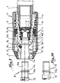
- the body of the female element A of the device shown in FIG. 1 consists of the assembly of two tubular parts, namely a main part 1 and a rear part 2, this assembly being effected by elastic snap-fitting of oblique tongues 1 a ( see Figure 3) behind an annular shoulder 2a of the workpiece 2. the latter holds in place the assembly formed by the tubular valve 3, the seat or seal 4 thereof, the valve holder 5 and the return spring 6; it will be noted that the valve holder 5 ensures the retention of the O-ring 7 intended to seal the fitting of the male element B of the device.
- the body 1-2 thus formed is surrounded by an operating sleeve formed by a sleeve 8 and an anterior sleeve 9.
- the sleeve 9 is integral with longitudinal extensions 9 a which end in a turned heel 9 b outwardly so as to snap into a corresponding window 8 a made for this purpose in the sleeve 8.
- each of the claws 10 a comprises a profiled head 10 b which is laterally secured to a locking protuberance 10 c , the profile of which appears clearly in FIGS. 1 and 2 and whose role will be explained below.
- Each end 10 b -10 c is engaged in a lumen 1 b of the part 1.
- a second ring 11 On the ring 10 slides a second ring 11 itself provided with two longitudinal claws 11 a , the free end of each of them being introduced into one of the two aforementioned slots 1 b .
- a spring 12 bearing against the rear stops 1 c of the part 1, tends to push the ring 11 to the left and to engage the claws more deeply in the slots 1 b , this movement however being limited by the stop of two teeth 11 b (of which only one appears in FIG. 3) of said ring 11 against the end of a flat 1 d made for this purpose on the periphery of the main part 1 of the body 1-2.
- the cylindrical body 13 of the male element B has an axial fitting end fitting 13 a on which the annular axial locking depression 13 b is practiced , which is bordered by a flange 13c whose wall is turned in the direction of said depression is provided right.
- the connecting member 13 For the coupling, the user inserts the connecting member 13 has in the axial bore 1e of the workpiece 1. As shown in Figure 4, the tip 13 has regrowth (clockwise) the valve 3 which opens against its spring 6, the seal 7 ensuring the tightness of the connection. It will be noted that the flange 13 c raises the protuberances 10 c which pass apart substantially radially.
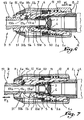
- the spring 6 of the valve 3 aided by the pressure of the fluid which fills the pipe associated with the male element B, tends to push the latter axially to the left (arrow F 2 in FIG. 7), so that the flange 13 c exerts traction on the heads 10 b of the claws 10 a , and that the two heads 10 b are trapped by the axial opening of the socket 9.
- the end piece 13 a and the body 13 therefore move towards the exterior (from right to left in Figure 7). Under these conditions, the valve 3 can close under the effect of its spring 6 and the pressurized fluid contained in the downstream pipe connected to the body 13 of the male element B escapes outside the device, the seal toroid 7 no longer ensuring its sealing function.
- the operator acts once again on the operating sleeve 8-9 by moving it from right to left (arrow F 3 in FIG. 8). Under these conditions, the opening of the socket 9 releases the head 10 b from the claws 10 a which can open (FIG. 9) under the effect of a tensile force exerted by the user on the male element B ( arrow F 4 ), leaving passage to the flange 13 c , it being observed that the aforementioned spacing movement is authorized by the protrusions 10 c which open by themselves as a result of their bearing against the oblique anterior edge 1 f lights 1 b acting like a ramp.
- the quick-coupling device with claws according to the present invention exhibits the safety of conventional double-trigger devices in spite of the straight profile of the wall of the flange 13 c which faces the annular locking depression 13 b .
- the invention is capable of being advantageously implemented in combination with quick couplings, the male element of which comprises a flange provided, on the side of the annular locking depression, with a wall which, without be oriented strictly orthogonal to the axis of the body of said element, constitutes an obstacle for the ends of the claws and defines a projecting part forming a support for the traction exerted by the heads thereof.
- Figure 10 illustrates such a male element 13 'whose annular depression 13' b is established to a semi-circular profile.
Landscapes
- Engineering & Computer Science (AREA)
- General Engineering & Computer Science (AREA)
- Mechanical Engineering (AREA)
- Quick-Acting Or Multi-Walled Pipe Joints (AREA)
Applications Claiming Priority (2)
| Application Number | Priority Date | Filing Date | Title |
|---|---|---|---|
| FR9607116A FR2749371B1 (fr) | 1996-06-03 | 1996-06-03 | Raccord rapide de securite pour la jonction amovible des canalisations |
| FR9607116 | 1996-06-03 |
Publications (2)
| Publication Number | Publication Date |
|---|---|
| EP0811797A1 true EP0811797A1 (de) | 1997-12-10 |
| EP0811797B1 EP0811797B1 (de) | 2000-09-06 |
Family
ID=9492850
Family Applications (1)
| Application Number | Title | Priority Date | Filing Date |
|---|---|---|---|
| EP97420082A Expired - Lifetime EP0811797B1 (de) | 1996-06-03 | 1997-06-02 | Sicherheitsschnellkupplung für die lösbare Verbindung von Rohrleitungen |
Country Status (5)
| Country | Link |
|---|---|
| EP (1) | EP0811797B1 (de) |
| DE (1) | DE69703003T2 (de) |
| DK (1) | DK0811797T3 (de) |
| ES (1) | ES2150748T3 (de) |
| FR (1) | FR2749371B1 (de) |
Cited By (4)
| Publication number | Priority date | Publication date | Assignee | Title |
|---|---|---|---|---|
| WO2010002523A1 (en) | 2008-07-03 | 2010-01-07 | Baxter International Inc | Port assembly for use with needleless connector |
| US9951821B1 (en) | 2017-01-11 | 2018-04-24 | Crossford International, Llc | Drive shaft coupling |
| CN109915678A (zh) * | 2019-04-12 | 2019-06-21 | 雷泽奇 | 一种快速夹紧螺纹气嘴的通气接头 |
| JP2024164877A (ja) * | 2023-05-16 | 2024-11-28 | 株式会社タツノ | 充填ノズル |
Families Citing this family (2)
| Publication number | Priority date | Publication date | Assignee | Title |
|---|---|---|---|---|
| US8062280B2 (en) | 2008-08-19 | 2011-11-22 | Baxter Healthcare S.A. | Port assembly for use with needleless connector |
| US8394080B2 (en) | 2009-05-14 | 2013-03-12 | Baxter International Inc. | Needleless connector with slider |
Citations (4)
| Publication number | Priority date | Publication date | Assignee | Title |
|---|---|---|---|---|
| US3873062A (en) * | 1973-11-30 | 1975-03-25 | Jerry Lynn Johnson | Air hose quick coupler |
| US4681350A (en) * | 1985-04-02 | 1987-07-21 | G.F. S.R.L. | Quick coupling connection for hoses |
| EP0340518A1 (de) * | 1988-05-04 | 1989-11-08 | UNIFLEX UTILTIME S.p.A. | Schnellkupplungsverbindung zum lösbaren Anschliessen von Schläuchen und Flüssigkeitsleitungen |
| EP0511436A1 (de) * | 1991-04-29 | 1992-11-04 | Kabushiki Kaisha Harmo Sogo Kenkyujo | Rohrverbindung |
-
1996
- 1996-06-03 FR FR9607116A patent/FR2749371B1/fr not_active Expired - Fee Related
-
1997
- 1997-06-02 EP EP97420082A patent/EP0811797B1/de not_active Expired - Lifetime
- 1997-06-02 DE DE69703003T patent/DE69703003T2/de not_active Expired - Lifetime
- 1997-06-02 DK DK97420082T patent/DK0811797T3/da active
- 1997-06-02 ES ES97420082T patent/ES2150748T3/es not_active Expired - Lifetime
Patent Citations (4)
| Publication number | Priority date | Publication date | Assignee | Title |
|---|---|---|---|---|
| US3873062A (en) * | 1973-11-30 | 1975-03-25 | Jerry Lynn Johnson | Air hose quick coupler |
| US4681350A (en) * | 1985-04-02 | 1987-07-21 | G.F. S.R.L. | Quick coupling connection for hoses |
| EP0340518A1 (de) * | 1988-05-04 | 1989-11-08 | UNIFLEX UTILTIME S.p.A. | Schnellkupplungsverbindung zum lösbaren Anschliessen von Schläuchen und Flüssigkeitsleitungen |
| EP0511436A1 (de) * | 1991-04-29 | 1992-11-04 | Kabushiki Kaisha Harmo Sogo Kenkyujo | Rohrverbindung |
Cited By (6)
| Publication number | Priority date | Publication date | Assignee | Title |
|---|---|---|---|---|
| WO2010002523A1 (en) | 2008-07-03 | 2010-01-07 | Baxter International Inc | Port assembly for use with needleless connector |
| US9951821B1 (en) | 2017-01-11 | 2018-04-24 | Crossford International, Llc | Drive shaft coupling |
| US11242888B2 (en) | 2017-01-11 | 2022-02-08 | Crossford International, Llc | Drive shaft coupling |
| CN109915678A (zh) * | 2019-04-12 | 2019-06-21 | 雷泽奇 | 一种快速夹紧螺纹气嘴的通气接头 |
| CN109915678B (zh) * | 2019-04-12 | 2023-11-21 | 雷泽奇 | 一种快速夹紧螺纹气嘴的通气接头 |
| JP2024164877A (ja) * | 2023-05-16 | 2024-11-28 | 株式会社タツノ | 充填ノズル |
Also Published As
| Publication number | Publication date |
|---|---|
| DE69703003T2 (de) | 2001-04-12 |
| DE69703003D1 (de) | 2000-10-12 |
| FR2749371B1 (fr) | 1998-08-14 |
| DK0811797T3 (da) | 2000-11-13 |
| FR2749371A1 (fr) | 1997-12-05 |
| EP0811797B1 (de) | 2000-09-06 |
| ES2150748T3 (es) | 2000-12-01 |
Similar Documents
| Publication | Publication Date | Title |
|---|---|---|
| EP0722063B1 (de) | Sicherheitsschnellkupplung für lösbare Verbindung von Rohrleitungen | |
| EP0023189B1 (de) | Schnellkupplungsvorrichtungen zum Verbinden von Rohrleitungen | |
| EP1064489B1 (de) | Steck-kupplung für rohre | |
| EP1557599B1 (de) | Schnellkupplung und Verfahren zum Lösen der ineinander gesteckten Teile der Schnellkupplung | |
| EP1934511B1 (de) | Sicherheits-schnellanschluss-kupplung für das zusammenbauen von zwei rohren | |
| EP0665401B1 (de) | Schnellverbindung | |
| FR2930904A1 (fr) | Assemblage de raccord rapide et outil de degagement | |
| FR2786848A1 (fr) | Coupleur a billes | |
| FR2713305A1 (fr) | Dispositif de raccord rapide pour tubulures d'échangeur de chaleur. | |
| EP0740101B1 (de) | Schnellkupplung mit einem selbständig belasteten Ventil | |
| EP0488844A1 (de) | Anschlussvorrichtung, insbesondere zur Verbindung eines Schlauches mit einem Automobilwärmeaustauscher | |
| EP1308662B1 (de) | Lösbare Schnellkupplung für mindestens eine Rohrleitung | |
| FR2795156A1 (fr) | Raccord encliquetable pour conduit de fluide, en particulier pour un circuit d'alimentation en carburant du moteur d'un vehicule automobile | |
| EP0811797B1 (de) | Sicherheitsschnellkupplung für die lösbare Verbindung von Rohrleitungen | |
| EP1427960B1 (de) | Verbindungsvorrichtung mit sicherer befestigung | |
| EP1146275A1 (de) | Lösbare Verbindungsvorrichtung für Rohre | |
| EP3628908B1 (de) | Flüssigkeitsanschlussvorrichtung für einen flüssigkeitskreislauf eines kraftfahrzeugs | |
| FR2511115A1 (fr) | Perfectionnements aux raccords rapides pour la jonction amovible des canalisations | |
| EP0742403B1 (de) | Fluiddichtkupplung | |
| FR2545908A1 (fr) | Raccord rapide de securite pour la jonction amovible des canalisations | |
| EP0327441B1 (de) | Wärmetauscher | |
| FR2728952A1 (fr) | Embout, dispositif et ensemble de liaison de conduites, notamment de conduites de gaz | |
| FR2610694A1 (fr) | Raccord rapide pour tuyaux et ou accessoires de tuyauteries | |
| FR2549197A1 (fr) | Raccord pour tuyaux equipe d'un collier de serrage verrouillable | |
| FR2501824A1 (fr) | Perfectionnements aux raccords rapides pour la jonction amovible des canalisations |
Legal Events
| Date | Code | Title | Description |
|---|---|---|---|
| PUAI | Public reference made under article 153(3) epc to a published international application that has entered the european phase |
Free format text: ORIGINAL CODE: 0009012 |
|
| AK | Designated contracting states |
Kind code of ref document: A1 Designated state(s): BE CH DE DK ES FR GB IT LI NL SE |
|
| 17P | Request for examination filed |
Effective date: 19980110 |
|
| AKX | Designation fees paid |
Free format text: BE CH DE DK ES FR GB IT LI NL SE |
|
| RBV | Designated contracting states (corrected) |
Designated state(s): BE CH DE DK ES FR GB IT LI NL SE |
|
| GRAG | Despatch of communication of intention to grant |
Free format text: ORIGINAL CODE: EPIDOS AGRA |
|
| GRAG | Despatch of communication of intention to grant |
Free format text: ORIGINAL CODE: EPIDOS AGRA |
|
| GRAH | Despatch of communication of intention to grant a patent |
Free format text: ORIGINAL CODE: EPIDOS IGRA |
|
| 17Q | First examination report despatched |
Effective date: 20000210 |
|
| GRAH | Despatch of communication of intention to grant a patent |
Free format text: ORIGINAL CODE: EPIDOS IGRA |
|
| GRAA | (expected) grant |
Free format text: ORIGINAL CODE: 0009210 |
|
| AK | Designated contracting states |
Kind code of ref document: B1 Designated state(s): BE CH DE DK ES FR GB IT LI NL SE |
|
| REG | Reference to a national code |
Ref country code: CH Ref legal event code: EP |
|
| GBT | Gb: translation of ep patent filed (gb section 77(6)(a)/1977) |
Effective date: 20000906 |
|
| REF | Corresponds to: |
Ref document number: 69703003 Country of ref document: DE Date of ref document: 20001012 |
|
| REG | Reference to a national code |
Ref country code: DK Ref legal event code: T3 |
|
| ITF | It: translation for a ep patent filed | ||
| REG | Reference to a national code |
Ref country code: ES Ref legal event code: FG2A Ref document number: 2150748 Country of ref document: ES Kind code of ref document: T3 |
|
| PLBE | No opposition filed within time limit |
Free format text: ORIGINAL CODE: 0009261 |
|
| STAA | Information on the status of an ep patent application or granted ep patent |
Free format text: STATUS: NO OPPOSITION FILED WITHIN TIME LIMIT |
|
| 26N | No opposition filed | ||
| REG | Reference to a national code |
Ref country code: GB Ref legal event code: IF02 |
|
| REG | Reference to a national code |
Ref country code: FR Ref legal event code: PLFP Year of fee payment: 19 |
|
| PGFP | Annual fee paid to national office [announced via postgrant information from national office to epo] |
Ref country code: ES Payment date: 20150626 Year of fee payment: 19 Ref country code: CH Payment date: 20150629 Year of fee payment: 19 Ref country code: GB Payment date: 20150629 Year of fee payment: 19 Ref country code: SE Payment date: 20150629 Year of fee payment: 19 Ref country code: DE Payment date: 20150629 Year of fee payment: 19 Ref country code: DK Payment date: 20150625 Year of fee payment: 19 |
|
| PGFP | Annual fee paid to national office [announced via postgrant information from national office to epo] |
Ref country code: NL Payment date: 20150626 Year of fee payment: 19 Ref country code: FR Payment date: 20150617 Year of fee payment: 19 |
|
| PGFP | Annual fee paid to national office [announced via postgrant information from national office to epo] |
Ref country code: BE Payment date: 20150629 Year of fee payment: 19 |
|
| PGFP | Annual fee paid to national office [announced via postgrant information from national office to epo] |
Ref country code: IT Payment date: 20150625 Year of fee payment: 19 |
|
| PG25 | Lapsed in a contracting state [announced via postgrant information from national office to epo] |
Ref country code: BE Free format text: LAPSE BECAUSE OF NON-PAYMENT OF DUE FEES Effective date: 20160630 |
|
| REG | Reference to a national code |
Ref country code: DE Ref legal event code: R119 Ref document number: 69703003 Country of ref document: DE |
|
| REG | Reference to a national code |
Ref country code: DK Ref legal event code: EBP Effective date: 20160630 |
|
| REG | Reference to a national code |
Ref country code: CH Ref legal event code: PL Ref country code: SE Ref legal event code: EUG |
|
| REG | Reference to a national code |
Ref country code: NL Ref legal event code: MM Effective date: 20160701 |
|
| PG25 | Lapsed in a contracting state [announced via postgrant information from national office to epo] |
Ref country code: SE Free format text: LAPSE BECAUSE OF NON-PAYMENT OF DUE FEES Effective date: 20160603 |
|
| GBPC | Gb: european patent ceased through non-payment of renewal fee |
Effective date: 20160602 |
|
| REG | Reference to a national code |
Ref country code: FR Ref legal event code: ST Effective date: 20170228 |
|
| PG25 | Lapsed in a contracting state [announced via postgrant information from national office to epo] |
Ref country code: DE Free format text: LAPSE BECAUSE OF NON-PAYMENT OF DUE FEES Effective date: 20170103 Ref country code: CH Free format text: LAPSE BECAUSE OF NON-PAYMENT OF DUE FEES Effective date: 20160630 Ref country code: FR Free format text: LAPSE BECAUSE OF NON-PAYMENT OF DUE FEES Effective date: 20160630 Ref country code: LI Free format text: LAPSE BECAUSE OF NON-PAYMENT OF DUE FEES Effective date: 20160630 |
|
| PG25 | Lapsed in a contracting state [announced via postgrant information from national office to epo] |
Ref country code: NL Free format text: LAPSE BECAUSE OF NON-PAYMENT OF DUE FEES Effective date: 20160701 Ref country code: GB Free format text: LAPSE BECAUSE OF NON-PAYMENT OF DUE FEES Effective date: 20160602 |
|
| PG25 | Lapsed in a contracting state [announced via postgrant information from national office to epo] |
Ref country code: IT Free format text: LAPSE BECAUSE OF NON-PAYMENT OF DUE FEES Effective date: 20160602 |
|
| PG25 | Lapsed in a contracting state [announced via postgrant information from national office to epo] |
Ref country code: DK Free format text: LAPSE BECAUSE OF NON-PAYMENT OF DUE FEES Effective date: 20160630 |
|
| REG | Reference to a national code |
Ref country code: ES Ref legal event code: FD2A Effective date: 20180507 |
|
| PG25 | Lapsed in a contracting state [announced via postgrant information from national office to epo] |
Ref country code: ES Free format text: LAPSE BECAUSE OF NON-PAYMENT OF DUE FEES Effective date: 20160603 |