EP0812027A2 - Verfahren zur Kalibrierung von Satellitennutzlasten mit Hybrid-Matrizen - Google Patents
Verfahren zur Kalibrierung von Satellitennutzlasten mit Hybrid-Matrizen Download PDFInfo
- Publication number
- EP0812027A2 EP0812027A2 EP97108935A EP97108935A EP0812027A2 EP 0812027 A2 EP0812027 A2 EP 0812027A2 EP 97108935 A EP97108935 A EP 97108935A EP 97108935 A EP97108935 A EP 97108935A EP 0812027 A2 EP0812027 A2 EP 0812027A2
- Authority
- EP
- European Patent Office
- Prior art keywords
- calibration
- output
- beam forming
- forming network
- power
- Prior art date
- Legal status (The legal status is an assumption and is not a legal conclusion. Google has not performed a legal analysis and makes no representation as to the accuracy of the status listed.)
- Granted
Links
Images


Classifications
-
- H—ELECTRICITY
- H01—ELECTRIC ELEMENTS
- H01Q—ANTENNAS, i.e. RADIO AERIALS
- H01Q3/00—Arrangements for changing or varying the orientation or the shape of the directional pattern of the waves radiated from an antenna or antenna system
- H01Q3/26—Arrangements for changing or varying the orientation or the shape of the directional pattern of the waves radiated from an antenna or antenna system varying the relative phase or relative amplitude of energisation between two or more active radiating elements; varying the distribution of energy across a radiating aperture
- H01Q3/267—Phased-array testing or checking devices
Definitions
- the invention is related to satellite communications payloads and, in particular, to a system and method for the calibration of satellite communications payloads.
- Satellite communication systems permit the establishment of circuits or communication channels in wide service areas and effectively allow the use of a small number of circuits by a large number of earth bound stations. Typical of such satellite communication systems are described by Roederer in U.S. Patent No. 5,115,248, Zacharatos et al. in U.S. Patent 4,907,004 and Egami et al. in U.S. Patent 4,618,831.
- a conventional prior art satellite communications payload system is shown in Figure 1.
- the payload system has a beam forming network 10 of conventional design which produces multiple outputs in response to one or more inputs. Each input is mapped to selected output ports with an appropriate gain and phase shift therebetween. Each output port of the beam forming network 10 is connected to the input of an associated amplifier 12.
- the outputs of selected groups of amplifier 12 are connected to the inputs of associated hybrid matrices 14-1 through 14-N.
- each hybrid matrix 14-1 through 14-N has four inputs and the associated group of amplifiers has four amplifiers 12, one connected to each of the four inputs.
- each hybrid matrix has four outputs, each of which is connected to a feed radiating element 18.
- the feed radiating elements 18 are placed at the focal point of a beam focusing device, such as a parabolic reflector 20.
- the invention is a communication payload system including a calibration system for measuring and maintaining the amplitude and phase transfer functions of the system within calibration.
- the payload system has a beam forming network having at least one input port and a plurality of output ports. Each input port is mapped to one or more selected output ports.
- the beam forming network provides an appropriate amplitude distribution and phase shift between the input ports and the output ports.
- An amplifier is connected to each output port of the beam forming network.
- the system includes at least one hybrid matrix having each of its inputs connected to a respective one of the amplifiers.
- a calibration RF absorbing load is connected to one of the outputs of each of the hybrid matrices. The calibration RF absorbing load functions as a calibration sample output port producing a calibration sample corresponding to the power output of the hybrid matrix.
- a calibration circuit provides power inputs to the beam forming network to generate signals at selected output ports of a beam forming network and generates corrections thereto in response to the calibration samples measured at the calibration sample output ports and a calibration pick-up antenna responsive to the power radiated by feed radiating elements.
- the calibration corrections are applied to the beam forming network to maintain the calibration of the communication payload system.
- the object of the invention is to provide a calibration system for a communication payload system.
- Another object of the invention is to provide extra outputs for the hybrid matrices that can be used for calibration.
- Another object of the invention is to increase the number of amplifiers for additional output power and increased payload effective isotropic radiated power (EIRP) without increasing the power output of the individual amplifiers.
- EIRP effective isotropic radiated power
- Another object of the invention is that the communication payload system be adaptable to any payload containing multiple beams, multiple amplifier and hybrid matrices that require calibration.
- Still another object of the invention is the use of normally loaded output ports of the hybrid matrices to provide a sample of the power in the hybrid matrix for the calibration of the payload system.
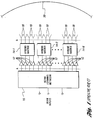
- the details of the system for calibration of satellite communications payloads is shown in Figure 2.
- the beam input or inputs are received by a beam forming network 30 as previously described with reference to Figure 1.
- the beam forming network 30 produces multiple outputs at its output ports identified as A in Figure 2 in response to each input. Each input maps to several of the output ports with appropriate attenuation and phase shift therebetween.
- Each output port of the beam forming network 30 is connected to the input of an associated amplifier 32.
- the outputs of selected groups of amplifiers 32 are connected to the inputs of associated hybrid matrices 34-1 through 34-N. As in the embodiment discussed relative to Figure 1, each hybrid matrix 34-1 through 34-N has four inputs and the associated group of amplifiers has four amplifiers 32, one connected to each of the four inputs, respectively.
- Each hybrid matrix 34 has four outputs as shown, but unlike the embodiment shown in Figure 1, only three of its outputs are connected to feed radiating elements 36. As taught by the prior art, each hybrid matrix may have more than the four inputs and more than the four outputs illustrated in the embodiment of Figure 2.
- the unused outputs from the hybrid matrix 34-1 through 34-N are terminated with an RF absorbing load as taught by Roederer in U.S. Patent No. 5,155,248 with reference to Figures 10B, 14B and 18B.
- the RF absorbing loads 38-1 through 38-N are modified to function as calibration output ports so that calibration samples of the power received by the RF absorbing loads 38-1 through 38-N are generated.
- These calibration samples of the power output from the unused outputs of the hybrid matrices 34-1 through 34-N and the output of a calibration pick-up antenna 44 are received by a calibration system 40 which measures the amplitude and phase transfer characteristics of the payload system both before and after the hybrid matrices 34.
- the measurement of the amplitude and phase transfer characteristics before the hybrid matrices is accomplished by applying power at a single beam forming network output port and measuring the power at the calibration output port.
- An estimate of the error in the phase transfer characteristics from the single beam forming network output port to the calibration output port is obtained by subtracting the measured value from a predetermined reference value.
- This predetermined reference value may be the value obtained from a preceding measurement or a theoretical value. This process is repeated for each output port of the beam forming network.
- the beam forming network 30 may be activated by the calibration system 40 to produce power at its output ports that result in power being applied to only one of the feed radiating elements which is detected by the calibration pick-up antenna 44.
- the signal detected by the calibration pick-up antenna is compared with predetermined values to determine the phase transfer function of the payload system to the feed radiating elements 36. This process is likewise repeated for each feed radiating element. The combination of the two measured phase transfer functions determines the transfer function of the payload.
- the calibration system 40 periodically activates the beam forming network 30 to power selected output ports and generates corrections applied to the beam forming network in response to the values generated at the calibration output ports 38 and the calibration pick-up antenna to maintain the calibration of the payload system.
- the calibration of the payload system may be automatically performed at routine intervals or may be initiated by a ground based station
- the feed radiating elements 36 are located at or near the focal point of a parabolic-shaped reflector 42 which focuses the energy radiated by the feed radiating elements 36 in one or more beams as is known in the art.
- the calibration process is initiated by activating the beam forming network 30 to apply power to a single output port as described in block 46. This application of power to a single output port will produce an output at a predetermined calibration output port.
- the calibration system will then measure the value of the power at the calibration output port (block 48) then compute an error between the measured value and a reference value, block 50.
- the reference value may be a theoretically derived value, or the value from a preceding measurement.
- the steps recited in blocks 46 through 50 are repeated for each output port of the beam forming network as indicated in block 52.
- the calibration system 40 will then activate the beam forming network 30 to apply power to the output ports preselected to produce an output at one of the feed radiating elements 36, block 54.
- the calibration system will then measure the value of the power radiated by the feed radiating element 36 using the calibration pick-up antenna 44, as indicated by block 56.
- the processes of blocks 56 and 58 are repeated until the power radiated by each feed radiating element 36 is measured as indicated by block 58.
- the calibration system will calculate corrections to the beam forming network and apply these corrections to the beam forming network to maintain the calibration of the payload system (block 60).
- FIG. 4 An alternate embodiment of the calibration output port for generating a calibration signal from the hybrid matrices 14 is illustrated in Figure 4.
- a sampling coupler 62 is connected to the lead between the hybrid matrix 14 and the feed radiating element 18.
- the calibration sample generated by the sampling coupler 62 is input to the calibration system 40 the same as the calibration sample produced by the RF absorbing load 38 discussed relative to Figure 2.
- the calibration process may be performed either in the absence of other signals input to the beam forming network or in the presence of other signals input into the beam forming network, the latter by coding or other means distinguishing the calibration signals from the other signals.
- the key parts of the invention are the use of a hybrid matrix system having more input ports than outputs ports to increase the total amount of power out without increasing the power out of the individual amplifiers and the use of the unused outputs of the hybrid matrices normally connected to a feed radiating element or an RF absorbing load to produce a sample of the power in the hybrid matrix to periodically calibrate the payload system.
Landscapes
- Radio Relay Systems (AREA)
- Variable-Direction Aerials And Aerial Arrays (AREA)
- Monitoring And Testing Of Transmission In General (AREA)
Applications Claiming Priority (2)
| Application Number | Priority Date | Filing Date | Title |
|---|---|---|---|
| US656974 | 1996-06-06 | ||
| US08/656,974 US5784030A (en) | 1996-06-06 | 1996-06-06 | Calibration method for satellite communications payloads using hybrid matrices |
Publications (3)
| Publication Number | Publication Date |
|---|---|
| EP0812027A2 true EP0812027A2 (de) | 1997-12-10 |
| EP0812027A3 EP0812027A3 (de) | 2000-01-12 |
| EP0812027B1 EP0812027B1 (de) | 2005-05-25 |
Family
ID=24635342
Family Applications (1)
| Application Number | Title | Priority Date | Filing Date |
|---|---|---|---|
| EP97108935A Expired - Lifetime EP0812027B1 (de) | 1996-06-06 | 1997-06-03 | Verfahren zur Kalibrierung von Satellitennutzlasten mit Hybrid-Matrizen |
Country Status (4)
| Country | Link |
|---|---|
| US (1) | US5784030A (de) |
| EP (1) | EP0812027B1 (de) |
| JP (1) | JP3004946B2 (de) |
| DE (1) | DE69733331T2 (de) |
Cited By (11)
| Publication number | Priority date | Publication date | Assignee | Title |
|---|---|---|---|---|
| US6046697A (en) * | 1997-09-05 | 2000-04-04 | Northern Telecom Limited | Phase control of transmission antennas |
| EP1126544A3 (de) * | 2000-02-16 | 2003-11-19 | The Boeing Company | System zur Kalibrierung und Charakterisierung eines Antennensystems und Verfahren zur Charakterisierung einer Gruppe von Antennenelementen |
| WO2004023600A1 (de) * | 2002-08-19 | 2004-03-18 | Kathrein-Werke Kg | Kalibriereinrichtung fur ein antennen-array und verfahren zur dessen kalibrierung |
| EP1583174A3 (de) * | 2004-03-30 | 2006-02-15 | Fujitsu Limited | Verfahren und Vorrichtung zur Phasenkalibrierung |
| US7132979B2 (en) | 2002-08-19 | 2006-11-07 | Kathrein-Werke Kg | Calibration apparatus for a switchable antenna array, and an associated operating method |
| WO2009027725A1 (en) * | 2007-08-31 | 2009-03-05 | Bae Systems Plc | Antenna calibration |
| US7787819B2 (en) | 2006-08-25 | 2010-08-31 | Space Systems / Loral, Inc. | Ground-based beamforming for satellite communications systems |
| US7990312B2 (en) | 2007-08-31 | 2011-08-02 | Bae Systems Plc | Antenna calibration |
| US8004456B2 (en) | 2007-08-31 | 2011-08-23 | Bae Systems Plc | Antenna calibration |
| WO2015065912A1 (en) * | 2013-11-04 | 2015-05-07 | Radio Frequency Systems, Inc. | Methods and systems for calibrating lte antenna systems |
| US10361762B2 (en) | 2017-12-06 | 2019-07-23 | Space Systems/Loral, Llc | Calibration of satellite beamforming channels |
Families Citing this family (14)
| Publication number | Priority date | Publication date | Assignee | Title |
|---|---|---|---|---|
| US6104935A (en) * | 1997-05-05 | 2000-08-15 | Nortel Networks Corporation | Down link beam forming architecture for heavily overlapped beam configuration |
| US5936592A (en) * | 1998-06-05 | 1999-08-10 | Ramanujam; Parthasarathy | Reconfigurable multiple beam satellite reflector antenna with an array feed |
| US6571081B1 (en) * | 1999-05-04 | 2003-05-27 | Hughes Electronics Corporation | Hybridized space/ground beam forming |
| US20070152869A1 (en) * | 2005-12-30 | 2007-07-05 | Woodington Walter G | Multichannel processing of signals in a radar system |
| CA2576778C (en) * | 2006-02-07 | 2014-09-02 | Xinping Huang | Self-calibrating multi-port circuit and method |
| AU2008291898B2 (en) * | 2007-08-31 | 2013-09-05 | Bae Systems Plc | Antenna calibration |
| JP4952681B2 (ja) * | 2008-08-07 | 2012-06-13 | 三菱電機株式会社 | アンテナ装置 |
| US9293820B2 (en) | 2013-03-13 | 2016-03-22 | The Boeing Company | Compensating for a non-ideal surface of a reflector in a satellite communication system |
| US9319000B2 (en) | 2013-07-31 | 2016-04-19 | The Boeing Company | Method and apparatus for improving leakage performance of a multi-port amplifier |
| US9848370B1 (en) * | 2015-03-16 | 2017-12-19 | Rkf Engineering Solutions Llc | Satellite beamforming |
| US10624051B2 (en) | 2015-07-02 | 2020-04-14 | The Boeing Company | System for measuring multi-port amplifier errors |
| US10320349B1 (en) | 2017-12-06 | 2019-06-11 | Space Systems/Loral, Llc | Multiport amplifier input network with compensation for output network gain and phase frequency response imbalance |
| US10284308B1 (en) | 2017-12-06 | 2019-05-07 | Space Systems/Loral, Llc | Satellite system calibration in active operational channels |
| US11005581B1 (en) * | 2020-02-07 | 2021-05-11 | Facebook, Inc. | Calibration of an antenna array that uses low-resolution phase shifters |
Family Cites Families (11)
| Publication number | Priority date | Publication date | Assignee | Title |
|---|---|---|---|---|
| NL286190A (de) * | 1961-12-01 | |||
| US4532518A (en) * | 1982-09-07 | 1985-07-30 | Sperry Corporation | Method and apparatus for accurately setting phase shifters to commanded values |
| JPS6178213A (ja) * | 1984-09-25 | 1986-04-21 | Nippon Telegr & Teleph Corp <Ntt> | 電力増幅装置 |
| US5412414A (en) * | 1988-04-08 | 1995-05-02 | Martin Marietta Corporation | Self monitoring/calibrating phased array radar and an interchangeable, adjustable transmit/receive sub-assembly |
| US4907004A (en) * | 1988-05-23 | 1990-03-06 | Spar Aerospace Limited | Power versatile satellite transmitter |
| DE3934155C2 (de) * | 1988-10-13 | 1999-10-07 | Mitsubishi Electric Corp | Verfahren zum Messen einer Amplitude und einer Phase jedes Antennenelementes einer phasengesteuerten Antennenanordnung sowie Antennenanordnung zum Durchführen des Verfahrens |
| US4926186A (en) * | 1989-03-20 | 1990-05-15 | Allied-Signal Inc. | FFT-based aperture monitor for scanning phased arrays |
| FR2652452B1 (fr) * | 1989-09-26 | 1992-03-20 | Europ Agence Spatiale | Dispositif d'alimentation d'une antenne a faisceaux multiples. |
| US5122806A (en) * | 1990-05-31 | 1992-06-16 | Hughes Aircraft Company | Method for finding defective active array modules using an FFT over phase states |
| US5625624A (en) * | 1993-10-21 | 1997-04-29 | Hughes Aircraft Company | High data rate satellite communication system |
| MX9605934A (es) * | 1994-06-03 | 1997-12-31 | Ericsson Telefon Ab L M | Calibracion de una disposicion de antena. |
-
1996
- 1996-06-06 US US08/656,974 patent/US5784030A/en not_active Expired - Lifetime
-
1997
- 1997-06-03 DE DE69733331T patent/DE69733331T2/de not_active Expired - Lifetime
- 1997-06-03 EP EP97108935A patent/EP0812027B1/de not_active Expired - Lifetime
- 1997-06-06 JP JP9149467A patent/JP3004946B2/ja not_active Expired - Lifetime
Cited By (16)
| Publication number | Priority date | Publication date | Assignee | Title |
|---|---|---|---|---|
| US6046697A (en) * | 1997-09-05 | 2000-04-04 | Northern Telecom Limited | Phase control of transmission antennas |
| EP1126544A3 (de) * | 2000-02-16 | 2003-11-19 | The Boeing Company | System zur Kalibrierung und Charakterisierung eines Antennensystems und Verfahren zur Charakterisierung einer Gruppe von Antennenelementen |
| WO2004023600A1 (de) * | 2002-08-19 | 2004-03-18 | Kathrein-Werke Kg | Kalibriereinrichtung fur ein antennen-array und verfahren zur dessen kalibrierung |
| US7068218B2 (en) | 2002-08-19 | 2006-06-27 | Kathrein-Werke Kg | Calibration device for an antenna array, antenna array and methods for antenna array operation |
| US7132979B2 (en) | 2002-08-19 | 2006-11-07 | Kathrein-Werke Kg | Calibration apparatus for a switchable antenna array, and an associated operating method |
| EP1583174A3 (de) * | 2004-03-30 | 2006-02-15 | Fujitsu Limited | Verfahren und Vorrichtung zur Phasenkalibrierung |
| US7106249B2 (en) | 2004-03-30 | 2006-09-12 | Fujitsu Limited | Phase calibration method and apparatus |
| US7787819B2 (en) | 2006-08-25 | 2010-08-31 | Space Systems / Loral, Inc. | Ground-based beamforming for satellite communications systems |
| US8270899B2 (en) | 2006-08-25 | 2012-09-18 | Space Systems/Loral, Inc. | Ground-based beamforming for satellite communications systems |
| WO2009027725A1 (en) * | 2007-08-31 | 2009-03-05 | Bae Systems Plc | Antenna calibration |
| US7990312B2 (en) | 2007-08-31 | 2011-08-02 | Bae Systems Plc | Antenna calibration |
| US8004456B2 (en) | 2007-08-31 | 2011-08-23 | Bae Systems Plc | Antenna calibration |
| US8004457B2 (en) | 2007-08-31 | 2011-08-23 | Bae Systems Plc | Antenna calibration |
| WO2015065912A1 (en) * | 2013-11-04 | 2015-05-07 | Radio Frequency Systems, Inc. | Methods and systems for calibrating lte antenna systems |
| US9300408B2 (en) | 2013-11-04 | 2016-03-29 | Alcatel-Lucent Shanghai Bell Co., Ltd | Methods and systems for calibrating LTE antenna systems |
| US10361762B2 (en) | 2017-12-06 | 2019-07-23 | Space Systems/Loral, Llc | Calibration of satellite beamforming channels |
Also Published As
| Publication number | Publication date |
|---|---|
| EP0812027B1 (de) | 2005-05-25 |
| DE69733331D1 (de) | 2005-06-30 |
| DE69733331T2 (de) | 2006-02-02 |
| JP3004946B2 (ja) | 2000-01-31 |
| US5784030A (en) | 1998-07-21 |
| JPH1093325A (ja) | 1998-04-10 |
| EP0812027A3 (de) | 2000-01-12 |
Similar Documents
| Publication | Publication Date | Title |
|---|---|---|
| US5784030A (en) | Calibration method for satellite communications payloads using hybrid matrices | |
| US5682165A (en) | Active array self calibration | |
| Ricardi et al. | Some characteristics of a communication satellite multiple-beam antenna | |
| US6339399B1 (en) | Antenna array calibration | |
| EP0981836B1 (de) | Verfahren und vorrichtung zur antennenkalibrierung | |
| Fukao et al. | The MU radar with an active phased array system: 1. Antenna and power amplifiers | |
| CN104597433B (zh) | 一种相控阵天线多波束自动校准装置及其自动校准方法 | |
| EP2223429B1 (de) | Multiportverstärker für kommunikationssatelliten | |
| US6233433B1 (en) | Apparatus and method of testing multi-beam satellite repeater in-orbit from a single ground station using a sampling and combining matrix | |
| EP0901183A2 (de) | Phasensteuerung in Übertragungsantennen | |
| WO1999054960A9 (en) | Phased array antenna calibration system and method using array clusters | |
| EP1178562A1 (de) | Kalibrierung einer Gruppenantenne | |
| CA2043135C (en) | Plural frequency matrix multiplexer | |
| EP1126544B1 (de) | System und Verfahren zur Kalibrierung eines Antennensystems | |
| US5771019A (en) | Method and system for determining the location of a sense antenna associated with a phased array communication system | |
| US7786948B2 (en) | Array antenna with embedded subapertures | |
| EP0930734A1 (de) | Verfahren und Apparat zur Bestimmung der Kennwerte von Komponenten eines Kommunikationskanals unter Last | |
| US6728650B2 (en) | High power amplifier operating point determination apparatus and method for satellite communications system | |
| JP3619162B2 (ja) | 可変利得電力増幅器に利得制御信号を与える方法 | |
| US20030064683A1 (en) | On board testing unit for multi-beam satellite and method of testing a satellite | |
| SE513340C2 (sv) | Kalibreringsmetod för fasstyrd gruppantenn | |
| EP2073381A1 (de) | Multiportverstärker für Kommunikationssatelliten | |
| US10624051B2 (en) | System for measuring multi-port amplifier errors | |
| JP2003124865A (ja) | 衛星搭載アンテナパターン測定システム、衛星搭載アンテナパターン測定システムにおける地球局及びマルチビーム通信衛星 | |
| SE509782C2 (sv) | Förfarande och anordning vid antennkalibrering samt användning av dessa i ett radiokommunikationssystem |
Legal Events
| Date | Code | Title | Description |
|---|---|---|---|
| PUAI | Public reference made under article 153(3) epc to a published international application that has entered the european phase |
Free format text: ORIGINAL CODE: 0009012 |
|
| AK | Designated contracting states |
Kind code of ref document: A2 Designated state(s): DE FR GB |
|
| RAP1 | Party data changed (applicant data changed or rights of an application transferred) |
Owner name: HUGHES ELECTRONICS CORPORATION |
|
| PUAL | Search report despatched |
Free format text: ORIGINAL CODE: 0009013 |
|
| AK | Designated contracting states |
Kind code of ref document: A3 Designated state(s): AT BE CH DE DK ES FI FR GB GR IE IT LI LU MC NL PT SE |
|
| 17P | Request for examination filed |
Effective date: 20000706 |
|
| AKX | Designation fees paid |
Free format text: DE FR GB |
|
| 17Q | First examination report despatched |
Effective date: 20040602 |
|
| GRAP | Despatch of communication of intention to grant a patent |
Free format text: ORIGINAL CODE: EPIDOSNIGR1 |
|
| GRAS | Grant fee paid |
Free format text: ORIGINAL CODE: EPIDOSNIGR3 |
|
| GRAA | (expected) grant |
Free format text: ORIGINAL CODE: 0009210 |
|
| AK | Designated contracting states |
Kind code of ref document: B1 Designated state(s): DE FR GB |
|
| REG | Reference to a national code |
Ref country code: GB Ref legal event code: FG4D |
|
| REF | Corresponds to: |
Ref document number: 69733331 Country of ref document: DE Date of ref document: 20050630 Kind code of ref document: P |
|
| PLBE | No opposition filed within time limit |
Free format text: ORIGINAL CODE: 0009261 |
|
| STAA | Information on the status of an ep patent application or granted ep patent |
Free format text: STATUS: NO OPPOSITION FILED WITHIN TIME LIMIT |
|
| ET | Fr: translation filed | ||
| 26N | No opposition filed |
Effective date: 20060228 |
|
| REG | Reference to a national code |
Ref country code: FR Ref legal event code: PLFP Year of fee payment: 20 |
|
| PGFP | Annual fee paid to national office [announced via postgrant information from national office to epo] |
Ref country code: GB Payment date: 20160627 Year of fee payment: 20 |
|
| PGFP | Annual fee paid to national office [announced via postgrant information from national office to epo] |
Ref country code: FR Payment date: 20160628 Year of fee payment: 20 |
|
| PGFP | Annual fee paid to national office [announced via postgrant information from national office to epo] |
Ref country code: DE Payment date: 20160628 Year of fee payment: 20 |
|
| REG | Reference to a national code |
Ref country code: DE Ref legal event code: R071 Ref document number: 69733331 Country of ref document: DE |
|
| REG | Reference to a national code |
Ref country code: GB Ref legal event code: PE20 Expiry date: 20170602 |
|
| PG25 | Lapsed in a contracting state [announced via postgrant information from national office to epo] |
Ref country code: GB Free format text: LAPSE BECAUSE OF EXPIRATION OF PROTECTION Effective date: 20170602 |