EP0812051A1 - Widerstandsvorrichtung, insbesondere zur Stromversorgung eines Elektromotors - Google Patents
Widerstandsvorrichtung, insbesondere zur Stromversorgung eines Elektromotors Download PDFInfo
- Publication number
- EP0812051A1 EP0812051A1 EP97401252A EP97401252A EP0812051A1 EP 0812051 A1 EP0812051 A1 EP 0812051A1 EP 97401252 A EP97401252 A EP 97401252A EP 97401252 A EP97401252 A EP 97401252A EP 0812051 A1 EP0812051 A1 EP 0812051A1
- Authority
- EP
- European Patent Office
- Prior art keywords
- support plate
- resistive
- plate
- insulating
- face
- Prior art date
- Legal status (The legal status is an assumption and is not a legal conclusion. Google has not performed a legal analysis and makes no representation as to the accuracy of the status listed.)
- Withdrawn
Links
- 239000000463 material Substances 0.000 claims abstract description 15
- 229910052751 metal Inorganic materials 0.000 claims abstract description 11
- 239000002184 metal Substances 0.000 claims abstract description 11
- 230000001681 protective effect Effects 0.000 claims abstract description 8
- 210000003298 dental enamel Anatomy 0.000 claims abstract description 6
- 239000004568 cement Substances 0.000 claims abstract description 4
- 239000011248 coating agent Substances 0.000 claims description 16
- 238000000576 coating method Methods 0.000 claims description 16
- 230000004224 protection Effects 0.000 claims description 10
- 239000004020 conductor Substances 0.000 claims description 9
- 239000012799 electrically-conductive coating Substances 0.000 claims description 4
- PNEYBMLMFCGWSK-UHFFFAOYSA-N aluminium oxide Inorganic materials [O-2].[O-2].[O-2].[Al+3].[Al+3] PNEYBMLMFCGWSK-UHFFFAOYSA-N 0.000 claims description 3
- ASNHGEVAWNWCRQ-UHFFFAOYSA-N 4-(hydroxymethyl)oxolane-2,3,4-triol Chemical compound OCC1(O)COC(O)C1O ASNHGEVAWNWCRQ-UHFFFAOYSA-N 0.000 claims 1
- 239000002966 varnish Substances 0.000 abstract description 3
- 229910052782 aluminium Inorganic materials 0.000 abstract description 2
- XAGFODPZIPBFFR-UHFFFAOYSA-N aluminium Chemical compound [Al] XAGFODPZIPBFFR-UHFFFAOYSA-N 0.000 abstract description 2
- 239000003779 heat-resistant material Substances 0.000 abstract description 2
- 230000003647 oxidation Effects 0.000 abstract description 2
- 238000007254 oxidation reaction Methods 0.000 abstract description 2
- 239000003973 paint Substances 0.000 abstract description 2
- 239000004411 aluminium Substances 0.000 abstract 1
- 238000009413 insulation Methods 0.000 abstract 1
- 238000010438 heat treatment Methods 0.000 description 5
- 238000003466 welding Methods 0.000 description 3
- 238000004378 air conditioning Methods 0.000 description 2
- 238000000151 deposition Methods 0.000 description 2
- 230000008030 elimination Effects 0.000 description 2
- 238000003379 elimination reaction Methods 0.000 description 2
- 239000010410 layer Substances 0.000 description 2
- 238000007650 screen-printing Methods 0.000 description 2
- 238000005476 soldering Methods 0.000 description 2
- 241001080024 Telles Species 0.000 description 1
- 230000002159 abnormal effect Effects 0.000 description 1
- 239000000853 adhesive Substances 0.000 description 1
- 238000004026 adhesive bonding Methods 0.000 description 1
- 230000001070 adhesive effect Effects 0.000 description 1
- HIGRAKVNKLCVCA-UHFFFAOYSA-N alumine Chemical compound C1=CC=[Al]C=C1 HIGRAKVNKLCVCA-UHFFFAOYSA-N 0.000 description 1
- 238000005219 brazing Methods 0.000 description 1
- 230000000295 complement effect Effects 0.000 description 1
- 230000037430 deletion Effects 0.000 description 1
- 238000012217 deletion Methods 0.000 description 1
- 230000008021 deposition Effects 0.000 description 1
- 239000012777 electrically insulating material Substances 0.000 description 1
- 238000011065 in-situ storage Methods 0.000 description 1
- 238000004519 manufacturing process Methods 0.000 description 1
- 229910000623 nickel–chromium alloy Inorganic materials 0.000 description 1
- 238000007639 printing Methods 0.000 description 1
- 238000002791 soaking Methods 0.000 description 1
- 239000007921 spray Substances 0.000 description 1
- 238000005507 spraying Methods 0.000 description 1
- 239000002344 surface layer Substances 0.000 description 1
- 238000009423 ventilation Methods 0.000 description 1
Images

Classifications
-
- H—ELECTRICITY
- H02—GENERATION; CONVERSION OR DISTRIBUTION OF ELECTRIC POWER
- H02K—DYNAMO-ELECTRIC MACHINES
- H02K23/00—DC commutator motors or generators having mechanical commutator; Universal AC/DC commutator motors
- H02K23/66—Structural association with auxiliary electric devices influencing the characteristic of, or controlling, the machine, e.g. with impedances or switches
-
- H—ELECTRICITY
- H01—ELECTRIC ELEMENTS
- H01C—RESISTORS
- H01C1/00—Details
- H01C1/01—Mounting; Supporting
- H01C1/012—Mounting; Supporting the base extending along and imparting rigidity or reinforcement to the resistive element
-
- H—ELECTRICITY
- H01—ELECTRIC ELEMENTS
- H01C—RESISTORS
- H01C1/00—Details
- H01C1/02—Housing; Enclosing; Embedding; Filling the housing or enclosure
- H01C1/034—Housing; Enclosing; Embedding; Filling the housing or enclosure the housing or enclosure being formed as coating or mould without outer sheath
-
- H—ELECTRICITY
- H01—ELECTRIC ELEMENTS
- H01C—RESISTORS
- H01C3/00—Non-adjustable metal resistors made of wire or ribbon, e.g. coiled, woven or formed as grids
- H01C3/10—Non-adjustable metal resistors made of wire or ribbon, e.g. coiled, woven or formed as grids the resistive element having zig-zag or sinusoidal configuration
- H01C3/12—Non-adjustable metal resistors made of wire or ribbon, e.g. coiled, woven or formed as grids the resistive element having zig-zag or sinusoidal configuration lying in one plane
-
- H—ELECTRICITY
- H02—GENERATION; CONVERSION OR DISTRIBUTION OF ELECTRIC POWER
- H02K—DYNAMO-ELECTRIC MACHINES
- H02K11/00—Structural association of dynamo-electric machines with electric components or with devices for shielding, monitoring or protection
- H02K11/20—Structural association of dynamo-electric machines with electric components or with devices for shielding, monitoring or protection for measuring, monitoring, testing, protecting or switching
- H02K11/25—Devices for sensing temperature, or actuated thereby
Definitions
- the invention relates to an electrical resistance device. intended for example to be mounted in the supply circuit of an electric motor or to be used as a heating resistor.
- Devices of this type are used in particular in motor vehicles to control fans in ventilation and heating or air conditioning circuits or to power drive motors for wiper blades or even to form means heating elements such as mirrors, windshield washers, injectors, etc ... and they have other applications, for example in household appliances (kettles, coffee maker ).
- Electric resistance devices which are flat. essentially consisting of a support plate having at least one insulating face, a resistive circuit made up of resistive segments applied to this face, electrical connection terminals in electrical connection with the resistive segments and means for protecting the circuit from the environment resistive applied to the support plate leaving the connection terminals visible.
- the resistant circuit consists of a coating produced in situ (printing, screen printing), which poses problems of manufacturing cost, resistance and performance.
- the object of the invention is to provide a simple, reliable and inexpensive solution to these problems.
- each resistive segment is cut from a sheet of resistive material.
- connection terminals are formed for example by depositing conductive material on the face of the support plate which receives the resistive element, or else they can be formed by a plate of electrically conductive material.
- Figure 8 is a plan view of a pair of closure plates.
- the device according to the invention represented in FIG. 1 essentially comprises a support plate (10) an element (12) of electrically conductive material with determined resistivity, forming the electrical resistance proper, and a plate (14) for covering and protecting .
- the support plate (10) is a metal plate shaped on one or more of its edges to present tabs (16) on a face of which are deposited strips (18) of electrically conductive material with very low resistivity.
- the strips with the underlying tabs constitute connection terminals.
- the faces of the plate (10) have previously been rendered non-electrically conductive by oxidation or by deposition (soaking, spraying with a spray gun, screen printing, etc.) of an insulating coating (enamel, varnish, painter, etc.) .).
- the plate (10) is for example made of aluminum with a surface layer of alumina resistant to relatively high electrical voltages (of the order of 1000 volts for example).
- the plate (10) is a sheet covered with an enamel.
- the resistive element (12) is cut with the press from a sheet or a sheet of an electrically conductive metal such as a nickel-chromium alloy for example.
- the resistive element comprises connection tabs (20) the number of which depends on the electrical circuit to be produced and is equal to the number of strips (18) of the plate (10), these tabs (20) being intended to be applied to the strips (18) when the resistive element (12) is placed on the plate (10).
- the protective plate (14) has substantially the same dimensions as the support plate (10), but is configured to leave at least part of the connection terminals (18) free.
- the protective plate (14) is preferably a metal plate whose faces include an electrically insulating coating (enamel oxide layer, varnish, paint, etc.).
- the resistive element (12) is placed on the face of the support plate (10) which carries the connection strips (18), its tabs (20) are applied to the ends of said strips (18 ), the electrical connection being maintained either by pressure or by welding, riveting soldering, bonding with a conductive adhesive or by any other suitable means. Then, the plate (14) is placed on the assembly thus formed and crimped or stapled on the support plate (10), so as to fully protect the resistive element (12) and to separate it from the surrounding medium.
- an electrically insulating and high temperature resistant coating material layer is provided between the support plate (10) and the protection plate (14).
- At least one fuse or a circuit breaker is incorporated in the resistive element.
- the fuse is advantageously formed by narrowing of the branches as indicated for example in (22) this narrowing causing a reduction in section which can be calibrated with precision and determined according to the electric overcurrent which must cause the interruption of the circuit.
- Such a narrowing is advantageously provided in each branch of the resistive element connected to a connection terminal, these narrowing may be different from each other. For example, in the case of supplying a fan with several speeds for a heating or air conditioning circuit of a motor vehicle, protection is obtained which is adapted for each operating speed, these protections being independent of each other and independent of the surrounding temperature.
- the device consists of the support plate (10) and the resistive element (12) of Figure 1, which are covered with a coating material (24) leaving no bare as the connection terminals (16 + 18).
- the coating material is for example refractory cement.
- the resistive element (12) is folded into a U and overlaps the support plate (10).
- Protective plates (14) cover the two parts of the resistive element (12) which are applied to the two faces of the support plate (10).
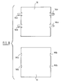
- connection tabs (16) are formed on one (or more) edge of a plate (25) of electrically conductive metal on either side of which are provided two plates (28) of electrically insulating material.
- resistive elements (12) of the same type as that of FIG. 1 are placed on either side of the insulating plates (28), their ends or connection lugs being fixed on the tabs (16) of the plate (26) by welding, by soldering, by riveting, by gluing or by any other equivalent means.
- the assembly thus formed is housed inside a metal case formed by a bottom (30) and a cover (32) intended to be crimped on the bottom (30).
- an edge of the latter may include an opening (34) for passage of the connection tabs (16).
- the bottom (30) and the cover (32) of the housing can be made of the materials already described for plates (10) or (14) of FIG. 1.
- another insulating plate (36) is interposed between the bottom ( 30) and the resistive element (12) as shown in FIG. 3, as well as between the resistive element (12) and the cover (32).
- a non-electrically conductive filling material can be injected or poured into the aforementioned housing, this filling material having good temperature resistance and a coefficient of thermal expansion compatible with those of the other elements of the device.
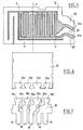
- FIG. 5 is a plan view of an example of a resistive sheet (12) which has been cut out in the hatched regions to allow resistive segments (R) to remain temporarily secured on one edge of the sheet by bridges (12a) which will be removed or cut when the resistive sheet has been put in place. Preferably, this elimination or this cut is carried out after complete completion of the device.
- the line P on the sheet represents the fold line of the sheet around the support.
- Figure 6 is a plan view of an example of an insulating or rendered insulating support plate (10) which has on one edge notches (10a) for receiving heels (18b) of complementary shape formed on an edge a plate (26) (fig. 7) of electrically conductive material, the opposite edge of which is cut out to form junction terminals (18).
- Material bridges (18a) secure the cut elements and will be removed or cut when the wafer has been inserted by embedding the heels (18b) in the notches (10a). Preferably this deletion will be carried out after complete completion of the device.
- the heels (18b) are fixed, for example by welding or brazing, to the junction legs of the resistive segments having elimination of bridges such as (12a) so that the resistive sheet (12) and the conductive plate (20) constitute an assembly that can be manipulated as such.
- FIG. 8 shows an example of two protective plates (14), one having lateral tabs (14a) and the other of the notches (14b) so that after these plates have been put in place and other of the insulating support provided with resistive segments, the legs of a plate can be bent to pass into the notches of the other plate and be folded over this other plate, to close the housing.
Landscapes
- Engineering & Computer Science (AREA)
- Microelectronics & Electronic Packaging (AREA)
- Power Engineering (AREA)
- Details Of Resistors (AREA)
- Apparatuses And Processes For Manufacturing Resistors (AREA)
Applications Claiming Priority (4)
| Application Number | Priority Date | Filing Date | Title |
|---|---|---|---|
| FR9606859 | 1996-06-04 | ||
| FR9606859A FR2749474A1 (fr) | 1996-06-04 | 1996-06-04 | Dispositif a resistance electrique, en particulier pour l'alimentation d'un moteur electrique |
| FR9706352 | 1997-05-23 | ||
| FR9706352A FR2749475B1 (fr) | 1996-06-04 | 1997-05-23 | Dispositif a resistance electrique, en particulier pour l'alimentation d'un moteur electrique |
Publications (1)
| Publication Number | Publication Date |
|---|---|
| EP0812051A1 true EP0812051A1 (de) | 1997-12-10 |
Family
ID=26232739
Family Applications (1)
| Application Number | Title | Priority Date | Filing Date |
|---|---|---|---|
| EP97401252A Withdrawn EP0812051A1 (de) | 1996-06-04 | 1997-06-04 | Widerstandsvorrichtung, insbesondere zur Stromversorgung eines Elektromotors |
Country Status (2)
| Country | Link |
|---|---|
| EP (1) | EP0812051A1 (de) |
| FR (1) | FR2749475B1 (de) |
Cited By (5)
| Publication number | Priority date | Publication date | Assignee | Title |
|---|---|---|---|---|
| FR2762441A1 (fr) * | 1997-04-22 | 1998-10-23 | Vishay Sa | Ceinture resistive souple et appareil comportant cette ceinture |
| FR2778057A1 (fr) * | 1998-04-27 | 1999-10-29 | Sofedit | Circuit resistif plat et applications de ce circuit |
| EP1067564A1 (de) * | 1999-07-09 | 2001-01-10 | Seima Elettronica S.r.l. | Widerstandsanordnung mit Schmelzsicherung |
| WO2007006271A1 (de) * | 2005-07-12 | 2007-01-18 | Temic Automotive Electric Motors Gmbh | Widerstandsbauelement für eine elektrische maschine |
| US11901850B2 (en) | 2019-12-18 | 2024-02-13 | Milwaukee Electric Tool Corporation | Power tool having stamped brake resistor |
Citations (6)
| Publication number | Priority date | Publication date | Assignee | Title |
|---|---|---|---|---|
| US4342020A (en) * | 1979-04-23 | 1982-07-27 | Siemens Aktiengesellschaft | Electrical network |
| EP0363191A2 (de) * | 1988-10-07 | 1990-04-11 | Fujikura Ltd. | Flacher Widerstand für Gebläsekontrolleinheit einer Automobil-Klimaanlage und Gebläsekontrolleinheit damit |
| DE3933956A1 (de) * | 1989-10-11 | 1991-04-25 | Asea Brown Boveri | Anordnung mit zwangsgekuehltem, elektrischem leistungswiderstand |
| EP0489529A1 (de) * | 1990-11-26 | 1992-06-10 | Pacific Engineering Co, Ltd. | Widerstandeinrichtung für einem Gebläse-Motor |
| EP0573265A1 (de) * | 1992-06-01 | 1993-12-08 | International Resistive Co., Inc. | Motorregler, inbesondere für ein Gebläse eines Kraftfahrzeuges |
| DE4429569A1 (de) * | 1994-08-19 | 1996-02-22 | Vitrohm Gmbh Co Kg | Verfahren zur Herstellung einer thermischen Sicherung |
-
1997
- 1997-05-23 FR FR9706352A patent/FR2749475B1/fr not_active Expired - Fee Related
- 1997-06-04 EP EP97401252A patent/EP0812051A1/de not_active Withdrawn
Patent Citations (6)
| Publication number | Priority date | Publication date | Assignee | Title |
|---|---|---|---|---|
| US4342020A (en) * | 1979-04-23 | 1982-07-27 | Siemens Aktiengesellschaft | Electrical network |
| EP0363191A2 (de) * | 1988-10-07 | 1990-04-11 | Fujikura Ltd. | Flacher Widerstand für Gebläsekontrolleinheit einer Automobil-Klimaanlage und Gebläsekontrolleinheit damit |
| DE3933956A1 (de) * | 1989-10-11 | 1991-04-25 | Asea Brown Boveri | Anordnung mit zwangsgekuehltem, elektrischem leistungswiderstand |
| EP0489529A1 (de) * | 1990-11-26 | 1992-06-10 | Pacific Engineering Co, Ltd. | Widerstandeinrichtung für einem Gebläse-Motor |
| EP0573265A1 (de) * | 1992-06-01 | 1993-12-08 | International Resistive Co., Inc. | Motorregler, inbesondere für ein Gebläse eines Kraftfahrzeuges |
| DE4429569A1 (de) * | 1994-08-19 | 1996-02-22 | Vitrohm Gmbh Co Kg | Verfahren zur Herstellung einer thermischen Sicherung |
Cited By (7)
| Publication number | Priority date | Publication date | Assignee | Title |
|---|---|---|---|---|
| FR2762441A1 (fr) * | 1997-04-22 | 1998-10-23 | Vishay Sa | Ceinture resistive souple et appareil comportant cette ceinture |
| EP0874374A1 (de) * | 1997-04-22 | 1998-10-28 | Vishay SA | Widerstandsfähiges flexibles Gürtel und damit versehenes Gerät |
| FR2778057A1 (fr) * | 1998-04-27 | 1999-10-29 | Sofedit | Circuit resistif plat et applications de ce circuit |
| EP1067564A1 (de) * | 1999-07-09 | 2001-01-10 | Seima Elettronica S.r.l. | Widerstandsanordnung mit Schmelzsicherung |
| WO2007006271A1 (de) * | 2005-07-12 | 2007-01-18 | Temic Automotive Electric Motors Gmbh | Widerstandsbauelement für eine elektrische maschine |
| US11901850B2 (en) | 2019-12-18 | 2024-02-13 | Milwaukee Electric Tool Corporation | Power tool having stamped brake resistor |
| US12328087B2 (en) | 2019-12-18 | 2025-06-10 | Milwaukee Electric Tool Corporation | Power tool having stamped brake resistor |
Also Published As
| Publication number | Publication date |
|---|---|
| FR2749475B1 (fr) | 1999-02-05 |
| FR2749475A1 (fr) | 1997-12-05 |
Similar Documents
| Publication | Publication Date | Title |
|---|---|---|
| EP1454509B1 (de) | Beheizbare scheibe versehen mit einer elektroleitenden beschichtung | |
| EP1632109B2 (de) | Elektrische heizeinrichtung insbesonderre für ein kraftfahrzeug | |
| EP0818872B1 (de) | Getriebemotor mit Träger für Lamellenkontakte | |
| FR2782597A1 (fr) | Module d'alimentation electrique | |
| EP3097630B1 (de) | Bürstenhalter für einen kraftfahrzeuganlasser mit wärmeschutzsystem und entsprechender kraftfahrzeuganlasser | |
| EP1986482B1 (de) | Zusatzvorrichtung für die elektrische Erwärmung eines Luftstroms, die zu einer Anlage zur Belüftung, Heizung und/oder Klimatisierung eines Kraftfahrzeugs gehört | |
| EP2766669B1 (de) | Isoliertes heizmodul für zusätzliches heizmittel | |
| EP2226586B1 (de) | Heizeinrichtung, insbesondere für ein Kraftfahrzeug | |
| EP0812051A1 (de) | Widerstandsvorrichtung, insbesondere zur Stromversorgung eines Elektromotors | |
| EP2979521A1 (de) | Steuermodul für eine elektrische anwendung | |
| EP0898807B1 (de) | Kollektorgehäuse-und motorgetriebeanschlusseinheit | |
| EP2536261A1 (de) | Elektronisches Leistungsmodul mit integierter Kapazität | |
| FR2749474A1 (fr) | Dispositif a resistance electrique, en particulier pour l'alimentation d'un moteur electrique | |
| FR2995473A1 (fr) | Machine electrique rotative | |
| FR2867602A1 (fr) | Collecteur pour moteur electrique | |
| EP1032114B1 (de) | Elektrisches Modul für Fahrzeug-, insbesondere Autolichtmaschine, und ein solches Modul und eine solche Lichtmaschine beinhaltende Anordnung | |
| FR2763760A1 (fr) | Moteur electrique avec circuit de commande de vitesse a resistance en couche epaisse | |
| EP4000136A1 (de) | Elektrischer verbinder aus metall für flexible elektrisch leitende streifen und zugehörige leitende streifenverbinderanordnung | |
| FR2994891A1 (fr) | Dispositif de chauffage electrique de fluide pour vehicule automobile, circuit de chauffage et appareil de chauffage et/ou de climatisation associes | |
| EP1914822B1 (de) | Batterie Schutzsystem | |
| WO1999063647A1 (fr) | Moteur electrique, notamment pour un equipement automobile | |
| EP0750388B1 (de) | Wechselstromgenerator für ein Kraftfahrzeug mit einer Bürstentragplatte mit umgossenem Entstörkondensator | |
| FR2682071A1 (fr) | Volant de direction d'un vehicule automobile. | |
| EP0656287B1 (de) | Getriebemotor, insbesondere für Kraftfahrzeug-Scheibenwischeranlage | |
| FR2800932A1 (fr) | Module electronique pour alternateur de vehicule, notamment automobile, et assemblage comportant un tel alternateur et un tel module |
Legal Events
| Date | Code | Title | Description |
|---|---|---|---|
| PUAI | Public reference made under article 153(3) epc to a published international application that has entered the european phase |
Free format text: ORIGINAL CODE: 0009012 |
|
| AK | Designated contracting states |
Kind code of ref document: A1 Designated state(s): BE DE ES FR GB IT |
|
| 17P | Request for examination filed |
Effective date: 19980508 |
|
| AKX | Designation fees paid |
Free format text: BE DE ES FR GB IT |
|
| RBV | Designated contracting states (corrected) |
Designated state(s): BE DE ES FR GB IT |
|
| 17Q | First examination report despatched |
Effective date: 19990903 |
|
| STAA | Information on the status of an ep patent application or granted ep patent |
Free format text: STATUS: THE APPLICATION IS DEEMED TO BE WITHDRAWN |
|
| 18D | Application deemed to be withdrawn |
Effective date: 20010103 |