EP0812595A1 - Dosing device - Google Patents
Dosing device Download PDFInfo
- Publication number
- EP0812595A1 EP0812595A1 EP97830277A EP97830277A EP0812595A1 EP 0812595 A1 EP0812595 A1 EP 0812595A1 EP 97830277 A EP97830277 A EP 97830277A EP 97830277 A EP97830277 A EP 97830277A EP 0812595 A1 EP0812595 A1 EP 0812595A1
- Authority
- EP
- European Patent Office
- Prior art keywords
- chamber
- stem
- piston
- dosing device
- container
- Prior art date
- Legal status (The legal status is an assumption and is not a legal conclusion. Google has not performed a legal analysis and makes no representation as to the accuracy of the status listed.)
- Withdrawn
Links
- 239000007788 liquid Substances 0.000 claims abstract description 21
- 239000003814 drug Substances 0.000 claims abstract description 19
- 229940079593 drug Drugs 0.000 claims abstract description 18
- 238000006073 displacement reaction Methods 0.000 claims abstract description 3
- 238000004891 communication Methods 0.000 claims description 7
- 230000000903 blocking effect Effects 0.000 claims description 2
- 230000003134 recirculating effect Effects 0.000 claims 1
- 239000000825 pharmaceutical preparation Substances 0.000 description 3
- 230000037396 body weight Effects 0.000 description 2
- 238000000034 method Methods 0.000 description 2
- 206010057362 Underdose Diseases 0.000 description 1
- 239000004480 active ingredient Substances 0.000 description 1
- 239000003242 anti bacterial agent Substances 0.000 description 1
- 229940088710 antibiotic agent Drugs 0.000 description 1
- 238000007906 compression Methods 0.000 description 1
- 230000006835 compression Effects 0.000 description 1
- 230000000881 depressing effect Effects 0.000 description 1
- 230000000694 effects Effects 0.000 description 1
- 238000009472 formulation Methods 0.000 description 1
- 238000005259 measurement Methods 0.000 description 1
- 239000000203 mixture Substances 0.000 description 1
- 238000012986 modification Methods 0.000 description 1
- 230000004048 modification Effects 0.000 description 1
- 238000002360 preparation method Methods 0.000 description 1
- 239000000344 soap Substances 0.000 description 1
- 239000000126 substance Substances 0.000 description 1
- 239000002544 virustatic Substances 0.000 description 1
- 230000001790 virustatic effect Effects 0.000 description 1
Images


Classifications
-
- G—PHYSICS
- G01—MEASURING; TESTING
- G01F—MEASURING VOLUME, VOLUME FLOW, MASS FLOW OR LIQUID LEVEL; METERING BY VOLUME
- G01F11/00—Apparatus requiring external operation adapted at each repeated and identical operation to measure and separate a predetermined volume of fluid or fluent solid material from a supply or container, without regard to weight, and to deliver it
- G01F11/02—Apparatus requiring external operation adapted at each repeated and identical operation to measure and separate a predetermined volume of fluid or fluent solid material from a supply or container, without regard to weight, and to deliver it with measuring chambers which expand or contract during measurement
- G01F11/021—Apparatus requiring external operation adapted at each repeated and identical operation to measure and separate a predetermined volume of fluid or fluent solid material from a supply or container, without regard to weight, and to deliver it with measuring chambers which expand or contract during measurement of the piston type
- G01F11/025—Apparatus requiring external operation adapted at each repeated and identical operation to measure and separate a predetermined volume of fluid or fluent solid material from a supply or container, without regard to weight, and to deliver it with measuring chambers which expand or contract during measurement of the piston type with manually operated pistons
- G01F11/028—Apparatus requiring external operation adapted at each repeated and identical operation to measure and separate a predetermined volume of fluid or fluent solid material from a supply or container, without regard to weight, and to deliver it with measuring chambers which expand or contract during measurement of the piston type with manually operated pistons the dosing device being provided with a dip tube and fitted to a container, e.g. to a bottleneck
-
- B—PERFORMING OPERATIONS; TRANSPORTING
- B05—SPRAYING OR ATOMISING IN GENERAL; APPLYING FLUENT MATERIALS TO SURFACES, IN GENERAL
- B05B—SPRAYING APPARATUS; ATOMISING APPARATUS; NOZZLES
- B05B11/00—Single-unit hand-held apparatus in which flow of contents is produced by the muscular force of the operator at the moment of use
- B05B11/01—Single-unit hand-held apparatus in which flow of contents is produced by the muscular force of the operator at the moment of use characterised by the means producing the flow
- B05B11/10—Pump arrangements for transferring the contents from the container to a pump chamber by a sucking effect and forcing the contents out through the dispensing nozzle
- B05B11/1001—Piston pumps
- B05B11/1005—Piston pumps with means for adjusting or modifying pump stroke
- B05B11/1007—Piston pumps with means for adjusting or modifying pump stroke by adjusting or modifying the pump end-of-sucking-stroke position
-
- B—PERFORMING OPERATIONS; TRANSPORTING
- B05—SPRAYING OR ATOMISING IN GENERAL; APPLYING FLUENT MATERIALS TO SURFACES, IN GENERAL
- B05B—SPRAYING APPARATUS; ATOMISING APPARATUS; NOZZLES
- B05B11/00—Single-unit hand-held apparatus in which flow of contents is produced by the muscular force of the operator at the moment of use
- B05B11/01—Single-unit hand-held apparatus in which flow of contents is produced by the muscular force of the operator at the moment of use characterised by the means producing the flow
- B05B11/10—Pump arrangements for transferring the contents from the container to a pump chamber by a sucking effect and forcing the contents out through the dispensing nozzle
- B05B11/1001—Piston pumps
- B05B11/1023—Piston pumps having an outlet valve opened by deformation or displacement of the piston relative to its actuating stem
Definitions
- the present invention relates to a precision dosing device for dosing liquid drugs. Specifically, this invention concerns a device for dispensing discrete doses of predetermined amounts of pharmaceutical preparations available in liquid form, suitable of being applied to the container of these substances.
- dosing devices by suction are already used, which allow the delivery of a certain amount of product usually by gently pressing the dispensing mechanism.
- These dosing devices consist of a supporting structure serving as a cap which can, for example, be screwed on the bottle's neck and which comprises a chamber connected both to the inside of the bottle and to the outside by means of a dispensing conduit.
- a non return valve is mounted in the conduit connecting the chamber to the inside of the bottle to keep closed the conduit under normal conditions.
- a piston sliding in the chamber is integral to a stem extending therefrom to operate the piston.
- the liquid dispensing conduit normally passes inside the stem and protrudes sideways.
- the object of the invention is to provide a precision dosing device for liquid drugs, suitable of being directly applied to the pharmaceutical preparation's container, allowing an accurate measurement of the desired dose easily and rapidly.
- the main feature of which consists in that the piston position inside the chamber can be adjusted by turning a ring pivotally supported by the cap structure and connected to the piston so that every angle of its angular displacement corresponds to a predetermined extent of sliding of the piston and consequently to a different volume available in the chamber, valved conduits connecting the chamber to the inside and outside of the container being further provided.
- a particular embodiment of the invention includes a slide as an integral part of the piston stem and moving on a helical guide of said ring; a second stem slidably arranged inside the said piston stem, and containing the liquid dispensing conduit.
- the accesses to the dispensing conduit, at least one of which leads to a liquid recirculation passage, are formed at the end of the second stem, inside the chamber, these accesses being equipped with valve means and selectively made available by rotating said second stem.
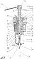
- 1 indicates a bottle for a pharmaceutical preparation in liquid form and 2 a dosing device according to the invention, mounted on the bottle neck, for example screwed on it.
- dosing device 2 comprises a cap structure 3 housing, in a known way, a second safety cap 4 and defining a cylindrical seat 5, the axis of which coincides with the axis of vertical symmetry of bottle 1 once the dosing device is mounted thereon.
- a cylinder wall 6 with conical bottom extends from bottom wall 5a of cylindrical seat 5, delimiting a chamber 7, the axis of which coincides with the axis of cylindrical seat 5.
- the centre of the bottom wall 5a of the cylindrical seat 5 has a through hole 8, in which a stem 9 of a piston 10 is engaged.
- Piston 10 is housed in chamber 7 and moves tightly along its walls thanks to gasket 17.
- the walls of through hole 8 and a portion 9a of the corresponding surface of stem 9 are axially grooved (as shown in figure 5) and mutually engaged to allow the axial sliding movement only and not the mutual rotation.
- Stem 9 and, correspondingly, piston 10 are axially hollow and contain a second stem 11 which protrudes from piston 10 with a head 12 moving inside an annular wall 13 which has two diametrally facing arched appendages 13a (figure 5) extending from piston 10 towards the bottom of chamber 7.
- a first portion 14a of a liquid discharge conduit from chamber 7 is formed inside second stem 11.
- An appendage 15 of cap 16 engages in the end of stem 11 opposite to head 12, a dispensing tube 18 projecting laterally from cap 16.
- Appendage 15 extends inside stem 9 and contains a second portion 14b of the liquid discharge conduit from chamber 7, axially aligned with first portion 14a, while a third portion 14c of said conduit is formed inside cap 16 and has an angled shape to connect the second portion 14b with the sideways extended dispensing tube 18.
- a control ring 20 is pivotally secured to cap structure 3 and a sleeve 19 extends therefrom in a coaxial relation to stems 9 and 11.
- Sleeve 19 has an annular lip 19a projecting outwardly and engaging with a corresponding perimetrical groove 5b formed on cylindrical seat 5 near bottom wall 5a.
- the internal wall of sleeve 19 is threaded and engages with a slide 21 coaxial to stems 9 and 11 and abutting against bottom wall 20a of ring 20, at one end of its stroke, and with a jut 9b formed on the outer surface of stem 9, at the other end.
- the inner surface of slide 21 and the corresponding surface portion 9c of stem 9 are grooved axially to allow their mutual sliding but not rotation (see figures 4 and 5).
- a row of notches 22 is formed, each corresponding to a dose, e.g. referred to body weight, while a reference index 23 is marked on the outer surface of cap structure 3.
- Ring 20 can be rotated with respect to cap structure 3 so that the selected notch 22 can be positioned to coincide with reference index 23.
- slide 21 By rotating ring 20 to select a specific dose, slide 21 is caused to move inside threaded sleeve 19. Stem 9 moves correspondingly together with slide 21 and positions piston 10 inside chamber 7 at a certain level from to the bottom, thus defining the proper volume corresponding to the selected dose.
- Chamber 7 is put into communication with the inside of the container through an opening 7a formed on its bottom wall, from which as in known dosing devices, a small tube 26 extends up to the bottom of the container. Opening 7a is normally kept closed from the inside of chamber 7 by valve means consisting of a ball 27 which closes opening 7a, and an elastic member 28, in particular a spiral compression spring fixed to ball 27, extending up to head 12 of stem 11 and coaxially wound to a pivot 29 projecting from head 12.
- valve means consisting of a ball 27 which closes opening 7a, and an elastic member 28, in particular a spiral compression spring fixed to ball 27, extending up to head 12 of stem 11 and coaxially wound to a pivot 29 projecting from head 12.
- Portion 14a of the discharge conduit is put into communication with the inside of chamber 7 by means of two lateral passages 30 formed in head 12 of stem 11 and diametrically aligned.
- passages 30 are closed by annular wall 13 extending from piston 10. They become accessible when second stem 11 is slid with respect to first stem 9.
- annular seat 31 is formed in cap 16 coaxially to the axis of stem 9, in which the top end of stem 9 engages for a length smaller than its depth.
- head 12 cannot rotate with respect to annular wall 13 when engaged in it. Indeed, as shown in figure 6, four angularly spaced recesses 32 are formed into the lateral surface of head 12, in which corresponding teeth engage (not shown) projecting inwardly from the annular wall 13.
- at least one other passage 33 extends radially with a right angle from the lateral surface of head 12, which follows stem 11 for a short length until it reaches the same level of at least two radial passages 34 formed on stem 9. This arrangement has the purpose of putting into communication chamber 7 to a space 35 between piston 10 and bottom wall 5a of cylindrical seat 5.
- stem 11 is rotated by 90°, moving passages 30 in line with arched portion 13a, thus freeing the inlets of angled passages 33.
- the possibility of allowing the excess liquid to return to the bottle is advantageous as it guarantees that the volume, determined by the position of piston 10 inside chamber 7, is actually full of liquid and consequently the dose is correctly measured. By repeating the above operations in reverse order, it is possible to restore the dispensing condition. It should also be noted that, when passages 30 are in line with arched portions 13a, any possibility of dispensing the drug, and consequently any risk of an uncontrolled use of the dosing device, is prevented.
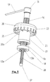
- An alternative embodiment of the dosing device according to the invention which is particularly useful for extracting large doses of a product, includes the possibility of mounting chamber 7 to the outside of the bottle's neck. This embodiment is shown in figure 7 and is not described in detail as its structure and function is similar to that described above.
Landscapes
- Physics & Mathematics (AREA)
- Fluid Mechanics (AREA)
- General Physics & Mathematics (AREA)
- Containers And Packaging Bodies Having A Special Means To Remove Contents (AREA)
- Closures For Containers (AREA)
- Medicines Containing Material From Animals Or Micro-Organisms (AREA)
Applications Claiming Priority (2)
| Application Number | Priority Date | Filing Date | Title |
|---|---|---|---|
| IT96FI000140A IT1286651B1 (it) | 1996-06-11 | 1996-06-11 | Dosatore di precisione per farmaci liquidi |
| ITFI960140 | 1996-06-11 |
Publications (1)
| Publication Number | Publication Date |
|---|---|
| EP0812595A1 true EP0812595A1 (en) | 1997-12-17 |
Family
ID=11351708
Family Applications (1)
| Application Number | Title | Priority Date | Filing Date |
|---|---|---|---|
| EP97830277A Withdrawn EP0812595A1 (en) | 1996-06-11 | 1997-06-10 | Dosing device |
Country Status (2)
| Country | Link |
|---|---|
| EP (1) | EP0812595A1 (it) |
| IT (1) | IT1286651B1 (it) |
Cited By (3)
| Publication number | Priority date | Publication date | Assignee | Title |
|---|---|---|---|---|
| CN107814079A (zh) * | 2017-11-28 | 2018-03-20 | 中山市华宝勒生活用品实业有限公司 | 一种准确定量的喷液盖 |
| CN108580086A (zh) * | 2018-03-16 | 2018-09-28 | 魏磊 | 一种喷头可旋转的喷雾器 |
| CN116374402A (zh) * | 2023-02-20 | 2023-07-04 | 雷昊 | 一种流量可定量调节的泵头 |
Citations (8)
| Publication number | Priority date | Publication date | Assignee | Title |
|---|---|---|---|---|
| FR1101114A (fr) * | 1953-05-22 | 1955-09-28 | Kopa Kolner Parfuemerie Apothe | Récipient distributeur de liquide en quantité réglable |
| FR1363410A (fr) * | 1963-05-03 | 1964-06-12 | Step Soc Tech Pulverisation | Vaporisateur à tube plongeur |
| US4081111A (en) * | 1976-10-12 | 1978-03-28 | Plasteco, Inc. | Adjustable volume setting mechanism for repeatable fluid discharge device |
| US4243159A (en) * | 1979-02-22 | 1981-01-06 | Spatz Corporation | Pump devices for dispensing fluids |
| US4273257A (en) * | 1977-07-18 | 1981-06-16 | Sherwood Medical Industries Inc. | Jar mounted pipettor |
| EP0086912A1 (en) * | 1982-02-05 | 1983-08-31 | Jencons (Scientific) Limited | Liquid dispensing devices |
| FR2573819A1 (fr) * | 1984-11-23 | 1986-05-30 | Aerosol Inventions Dev | Procede pour limiter le debit d'une pompe, petite pompe manuelle et seringue compte-gouttes mettant en oeuvre ce procede |
| FR2714119A1 (fr) * | 1993-12-22 | 1995-06-23 | Step | Pompe manuelle de pulvérisation à dose ajustable. |
-
1996
- 1996-06-11 IT IT96FI000140A patent/IT1286651B1/it active IP Right Grant
-
1997
- 1997-06-10 EP EP97830277A patent/EP0812595A1/en not_active Withdrawn
Patent Citations (8)
| Publication number | Priority date | Publication date | Assignee | Title |
|---|---|---|---|---|
| FR1101114A (fr) * | 1953-05-22 | 1955-09-28 | Kopa Kolner Parfuemerie Apothe | Récipient distributeur de liquide en quantité réglable |
| FR1363410A (fr) * | 1963-05-03 | 1964-06-12 | Step Soc Tech Pulverisation | Vaporisateur à tube plongeur |
| US4081111A (en) * | 1976-10-12 | 1978-03-28 | Plasteco, Inc. | Adjustable volume setting mechanism for repeatable fluid discharge device |
| US4273257A (en) * | 1977-07-18 | 1981-06-16 | Sherwood Medical Industries Inc. | Jar mounted pipettor |
| US4243159A (en) * | 1979-02-22 | 1981-01-06 | Spatz Corporation | Pump devices for dispensing fluids |
| EP0086912A1 (en) * | 1982-02-05 | 1983-08-31 | Jencons (Scientific) Limited | Liquid dispensing devices |
| FR2573819A1 (fr) * | 1984-11-23 | 1986-05-30 | Aerosol Inventions Dev | Procede pour limiter le debit d'une pompe, petite pompe manuelle et seringue compte-gouttes mettant en oeuvre ce procede |
| FR2714119A1 (fr) * | 1993-12-22 | 1995-06-23 | Step | Pompe manuelle de pulvérisation à dose ajustable. |
Cited By (3)
| Publication number | Priority date | Publication date | Assignee | Title |
|---|---|---|---|---|
| CN107814079A (zh) * | 2017-11-28 | 2018-03-20 | 中山市华宝勒生活用品实业有限公司 | 一种准确定量的喷液盖 |
| CN108580086A (zh) * | 2018-03-16 | 2018-09-28 | 魏磊 | 一种喷头可旋转的喷雾器 |
| CN116374402A (zh) * | 2023-02-20 | 2023-07-04 | 雷昊 | 一种流量可定量调节的泵头 |
Also Published As
| Publication number | Publication date |
|---|---|
| IT1286651B1 (it) | 1998-07-15 |
| ITFI960140A1 (it) | 1997-12-11 |
Similar Documents
| Publication | Publication Date | Title |
|---|---|---|
| US5843042A (en) | Oral medicine dispensing device having a metered syringe component and reservoir | |
| JP4632510B2 (ja) | 噴霧ノズルを備えた鼻内部への送り器具 | |
| AU776738B2 (en) | Multi-dose infusion pump | |
| DK2170216T3 (en) | Animal drug delivery agent | |
| US10213558B2 (en) | Drug delivery device | |
| US4995867A (en) | Aural medication dispenser | |
| CN108348398B (zh) | 计量装置 | |
| US8563013B2 (en) | Systems and methods for delivering a fluid drug | |
| JPH10225516A (ja) | 非経口施与用販売ユニット、非経口施与を実施するための装置並びに上記販売ユニットのための再充填ユニット | |
| US10718651B2 (en) | Adjustable dosing dispensers and methods for using the same | |
| US3337096A (en) | Pump-type dispenser | |
| DK167204B1 (da) | Applikator til behandling af hud | |
| US7077831B2 (en) | Ophthalmic fluid dispenser | |
| AU643404B2 (en) | Double tip drug dispensing and metering device | |
| EP0812595A1 (en) | Dosing device | |
| WO2003004080A1 (en) | Syringe for the injection of a medicament | |
| KR20240067897A (ko) | 의료용 전달 장치 | |
| JPS5910986Y2 (ja) | 液体の充填容器 | |
| US11517505B2 (en) | Integrated container and dosing device for liquid medication delivery | |
| US11946788B2 (en) | Airless metered fluid dispenser assembly | |
| KR20220041920A (ko) | 계량 기구, 및 그것을 구비한 정량 토출 용기 그리고 정량 도포 도구 | |
| HK40107528A (zh) | 医疗输送装置 | |
| MXPA97001067A (es) | Unidad de venta para la aplicacion parenteral,dispositivo para la realizacion de la aplicacion parenteral asi como unidad de relleno para la unidadde venta anterior | |
| HK1257131B (en) | Dosing device |
Legal Events
| Date | Code | Title | Description |
|---|---|---|---|
| PUAI | Public reference made under article 153(3) epc to a published international application that has entered the european phase |
Free format text: ORIGINAL CODE: 0009012 |
|
| AK | Designated contracting states |
Kind code of ref document: A1 Designated state(s): DE FR GB |
|
| AKX | Designation fees paid |
Free format text: DE FR GB |
|
| RBV | Designated contracting states (corrected) |
Designated state(s): DE FR GB |
|
| RBV | Designated contracting states (corrected) |
Designated state(s): DE FR GB |
|
| STAA | Information on the status of an ep patent application or granted ep patent |
Free format text: STATUS: THE APPLICATION IS DEEMED TO BE WITHDRAWN |
|
| 18D | Application deemed to be withdrawn |
Effective date: 19980618 |