EP0812666A2 - Procédé pour le contrÔle des coupes transversales et scie pour sa mise en oeuvre - Google Patents
Procédé pour le contrÔle des coupes transversales et scie pour sa mise en oeuvre Download PDFInfo
- Publication number
- EP0812666A2 EP0812666A2 EP97109162A EP97109162A EP0812666A2 EP 0812666 A2 EP0812666 A2 EP 0812666A2 EP 97109162 A EP97109162 A EP 97109162A EP 97109162 A EP97109162 A EP 97109162A EP 0812666 A2 EP0812666 A2 EP 0812666A2
- Authority
- EP
- European Patent Office
- Prior art keywords
- log
- cross
- diameter
- determined
- cut saw
- Prior art date
- Legal status (The legal status is an assumption and is not a legal conclusion. Google has not performed a legal analysis and makes no representation as to the accuracy of the status listed.)
- Withdrawn
Links
Images
Classifications
-
- B—PERFORMING OPERATIONS; TRANSPORTING
- B27—WORKING OR PRESERVING WOOD OR SIMILAR MATERIAL; NAILING OR STAPLING MACHINES IN GENERAL
- B27B—SAWS FOR WOOD OR SIMILAR MATERIAL; COMPONENTS OR ACCESSORIES THEREFOR
- B27B1/00—Methods for subdividing trunks or logs essentially involving sawing
- B27B1/007—Methods for subdividing trunks or logs essentially involving sawing taking into account geometric properties of the trunks or logs to be sawn, e.g. curvature
-
- B—PERFORMING OPERATIONS; TRANSPORTING
- B23—MACHINE TOOLS; METAL-WORKING NOT OTHERWISE PROVIDED FOR
- B23D—PLANING; SLOTTING; SHEARING; BROACHING; SAWING; FILING; SCRAPING; LIKE OPERATIONS FOR WORKING METAL BY REMOVING MATERIAL, NOT OTHERWISE PROVIDED FOR
- B23D59/00—Accessories specially designed for sawing machines or sawing devices
- B23D59/001—Measuring or control devices, e.g. for automatic control of work feed pressure on band saw blade
-
- B—PERFORMING OPERATIONS; TRANSPORTING
- B23—MACHINE TOOLS; METAL-WORKING NOT OTHERWISE PROVIDED FOR
- B23D—PLANING; SLOTTING; SHEARING; BROACHING; SAWING; FILING; SCRAPING; LIKE OPERATIONS FOR WORKING METAL BY REMOVING MATERIAL, NOT OTHERWISE PROVIDED FOR
- B23D59/00—Accessories specially designed for sawing machines or sawing devices
- B23D59/008—Accessories specially designed for sawing machines or sawing devices comprising computers
-
- B—PERFORMING OPERATIONS; TRANSPORTING
- B27—WORKING OR PRESERVING WOOD OR SIMILAR MATERIAL; NAILING OR STAPLING MACHINES IN GENERAL
- B27B—SAWS FOR WOOD OR SIMILAR MATERIAL; COMPONENTS OR ACCESSORIES THEREFOR
- B27B1/00—Methods for subdividing trunks or logs essentially involving sawing
- B27B1/002—Methods for subdividing trunks or logs essentially involving sawing by cross-cutting
-
- B—PERFORMING OPERATIONS; TRANSPORTING
- B27—WORKING OR PRESERVING WOOD OR SIMILAR MATERIAL; NAILING OR STAPLING MACHINES IN GENERAL
- B27B—SAWS FOR WOOD OR SIMILAR MATERIAL; COMPONENTS OR ACCESSORIES THEREFOR
- B27B31/00—Arrangements for conveying, loading, turning, adjusting, or discharging the log or timber, specially designed for saw mills or sawing machines
- B27B31/003—Arrangements for conveying, loading, turning, adjusting, or discharging the log or timber, specially designed for saw mills or sawing machines with rollers
Definitions
- the invention relates to a method for controlling saw cuts by means of a cross-cut saw device on a log which is advanced in the longitudinal direction.
- the invention further relates to a cross-cut saw device for logs with an infeed conveyor, with a centering device arranged in the downstream end of the infeed conveyor and with a downstream crosscut saw arrangement.
- the cutting of logs by chop saws can be done by measuring the length and diameter of the logs in a measuring device. Taking into account the required log sections, the logs are divided in the most optimized form so that the desired log sections are produced with the smallest possible proportion of residual pieces that are no longer usable.
- a suitable measuring device in which the log is on a can be raised and stored above the log a U-shaped sensor in the longitudinal axis of the log is known from DE 34 17 717 C2.
- DE 94 01 780 U also discloses a cross-cut saw device in which the end of the log is centered shortly before the cross-cut saw with flaps which can be pivoted into the conveying path of the log after the conveying movement has ended.
- a measuring arrangement for the height of the log is integrated in the flaps by means of parallel light barriers.
- the appropriate cross-cut saw can be selected for several saws and, depending on the height, can be set to a standby position to carry out the saw cut.
- the present invention is based on the problem of reducing the mechanical effort required for the optimized control of saw cuts.
- a method of the type mentioned at the outset is characterized in that the diameter of the trunk wood and information about the remaining length of the trunk wood are continuously determined during the preliminary conveying and that, depending on this, it is determined which crosscut cut for the optimal division of the trunk wood into Dependent on a stock of desired section lengths and diameter, if necessary.
- the method according to the invention enables the optimization of the saw cuts during the forward conveying of the log to the cross-cut saw device by constantly determining the diameter of the log during the forward conveying, so that there is also information about the diameter profile of the log to be cut to length by the cross-cut saw.
- the diameter is preferably determined at the end of the conveying path downstream of the conveying direction in front of the cross-cut saw arrangement.
- the remaining length can be determined in a simple manner by providing a sensor on the conveyor device at a sufficient distance from the chop saw arrangement, which determines the point in time at which the pre-conveyed log is no longer within the light grid, so that at this point in time the remaining length of the log corresponding to the distance to the cross-cut saw is available.
- an average conicity of the trunk wood is determined from the changes in the diameter and a model of the trunk wood is calculated using the determined average conicity and the determined remaining length of the trunk wood, which is used as the basis for the division by the cross cuts.
- the previous measurement of the log can be omitted without having to do without a corresponding optimization of the saw cuts.
- a cross-cut saw device of the type mentioned at the outset is further characterized according to the invention in that the centering device is formed by two roller devices which can be moved to the side against the log under pretension in the conveying path of the infeed conveyor and which have measuring sensors for the degree of movement in the conveying path of the infeed conveyor are provided and that an evaluation device is provided for determining the diameter of the log from the output signals of the measuring transducers.
- the centering device itself is already the sensor for the diameter of the log, since the movement of the roller devices into the conveying path of the infeed conveyor, which is detected by the measuring transducer, enables the diameter of the log to be determined directly.
- the roller devices can be pivoted into the conveying path and the measuring transducers are designed to determine the pivoting angle.
- the roller devices can preferably be driven in synchronization with the infeed conveyor and have a surface designed for slip-free transport of the log, for example in the form of spiked rollers. Due to the slip-free advance of the logs, the accuracy of the division through the saw cuts can be significantly improved.
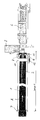
- the drawing shows a schematic plan view of a cross-cut saw device with an infeed conveyor 1 in the form of a conveyor belt on which log 2 is advanced in its longitudinal direction in the direction of a cross-cut saw device 3 (arrow A).
- the chop saw device 3 contains in a known manner a vertically and / or horizontally movable saw 4, usually in the form of a pivotable chain saw or a circular saw.
- conical guide rollers 5 for supporting the log 2 during the saw cut, which produce the transition to a conveyor belt 6.
- the drawing shows at the entrance of the infeed conveyor 1 an optical detection device 7, preferably in the form of a light grid, with which the presence or absence of log 2 at the level of the detection device 7 can be detected.
- an optical detection device 7 preferably in the form of a light grid, with which the presence or absence of log 2 at the level of the detection device 7 can be detected.
- the log 2 has a remaining length X which is equal to the distance X between the saw 4 and the optical detection device 7.
- a centering device 8 is arranged, which consists of spiked rollers 10 which can be pivoted into the conveying path of the infeed conveyor 1 with levers 9.
- An evaluation device 11 detects the current angular position of the two levers 9 and uses this to determine the distance between the spiked rollers 10, which corresponds to the current diameter Dx of the log 2 at the end of the log 2 directed towards the cross-cut saw 3.
- the evaluation device 11 also determines (in conjunction with a computer) the function of changing the diameter Dx over the length of the log 2 and is therefore able to create a model of the log 2 from the extrapolated conicity of the log 2, with which the The diameter of the log 2 on the remaining length of the log 2 is forecast and used to optimize the cuts by the cross-cut saw 3.
- the spiked rollers 10 are driven synchronously with the infeed conveyor 1 by a drive motor 12, so that it is ensured that the trunk wood 2 is conveyed to the cross-cut saw device 3 without slippage after the determination of the diameter Dx, so that cutting errors due to any slippage of the conveyor are avoided.
- the centering device 8 thus fulfills a multiple function, which not only consists in centering the log 2 for the cross-cut saw device 3, but also serves for the slip-free transport of the log 2 and for determining the diameter Dx of the log 2.
Landscapes
- Life Sciences & Earth Sciences (AREA)
- Engineering & Computer Science (AREA)
- Mechanical Engineering (AREA)
- Wood Science & Technology (AREA)
- Forests & Forestry (AREA)
- Manufacture Of Wood Veneers (AREA)
Applications Claiming Priority (2)
| Application Number | Priority Date | Filing Date | Title |
|---|---|---|---|
| DE19623983 | 1996-06-15 | ||
| DE1996123983 DE19623983C2 (de) | 1996-06-15 | 1996-06-15 | Verfahren zur Steuerung von Sägeschnitten und Kappsägevorrichtung hierfür |
Publications (2)
| Publication Number | Publication Date |
|---|---|
| EP0812666A2 true EP0812666A2 (fr) | 1997-12-17 |
| EP0812666A3 EP0812666A3 (fr) | 2000-02-23 |
Family
ID=7797073
Family Applications (1)
| Application Number | Title | Priority Date | Filing Date |
|---|---|---|---|
| EP97109162A Withdrawn EP0812666A3 (fr) | 1996-06-15 | 1997-06-06 | Procédé pour le contrôle des coupes transversales et scie pour sa mise en oeuvre |
Country Status (2)
| Country | Link |
|---|---|
| EP (1) | EP0812666A3 (fr) |
| DE (1) | DE19623983C2 (fr) |
Cited By (4)
| Publication number | Priority date | Publication date | Assignee | Title |
|---|---|---|---|---|
| EP0819506A3 (fr) * | 1996-06-15 | 2000-02-23 | Holtec GmbH & Co. | Scie à tronçonner des troncs d'arbre |
| GR20010100386A (el) * | 2001-08-03 | 2003-04-24 | Χρηστος Δημακος | Συστημα καθοδηγησης εντολων για τον προσδιορισμο ολων των δυνατων χαραξεων μιας ορθογωνιας επιφανειας με βαση μια μικροτερη ορθογωνια επιφανεια ή πολλαπλασια αυτης. |
| WO2005035214A1 (fr) * | 2003-09-17 | 2005-04-21 | Siempelkamp Maschinen- Und Anlagenbau Gmbh & Co. Kg | Reservoir a materiau d'epandage comprenant un dispositif de deversement pour epandre le materiau d'epandage |
| US9400163B2 (en) | 2012-06-06 | 2016-07-26 | Deere & Company | Method and apparatus for processing a length of material |
Family Cites Families (6)
| Publication number | Priority date | Publication date | Assignee | Title |
|---|---|---|---|---|
| US4330019A (en) * | 1982-03-11 | 1982-05-18 | King, Murphy & Associates, Ltd. | Method and apparatus for sawing logs into lengths |
| DE3417717C2 (de) * | 1984-05-12 | 1987-02-26 | HOLTEC Gölz, Sänger & Massierer GmbH & Co KG, 5374 Hellenthal | Vorrichtung zum Transport und zur Vermessung von Rundholz |
| DE8603072U1 (de) * | 1986-02-06 | 1987-07-30 | Josef Aigner KG, 8225 Traunreut | Durchlaufkappsägeautomat |
| DE9401780U1 (de) * | 1994-02-03 | 1994-03-31 | HOLTEC GmbH & Co. Anlagenbau zur Holzbearbeitung, 53940 Hellenthal | Kappsägevorrichtung für Stammholz |
| CA2131056C (fr) * | 1994-08-29 | 2000-07-18 | Robert James Murray | Appareil servant a scier des grumes et methode connexe |
| DE29610567U1 (de) * | 1996-06-15 | 1996-08-29 | HOLTEC GmbH & Co. Anlagenbau zur Holzbearbeitung, 53940 Hellenthal | Kappsägevorrichtung für Stammholz |
-
1996
- 1996-06-15 DE DE1996123983 patent/DE19623983C2/de not_active Expired - Fee Related
-
1997
- 1997-06-06 EP EP97109162A patent/EP0812666A3/fr not_active Withdrawn
Cited By (4)
| Publication number | Priority date | Publication date | Assignee | Title |
|---|---|---|---|---|
| EP0819506A3 (fr) * | 1996-06-15 | 2000-02-23 | Holtec GmbH & Co. | Scie à tronçonner des troncs d'arbre |
| GR20010100386A (el) * | 2001-08-03 | 2003-04-24 | Χρηστος Δημακος | Συστημα καθοδηγησης εντολων για τον προσδιορισμο ολων των δυνατων χαραξεων μιας ορθογωνιας επιφανειας με βαση μια μικροτερη ορθογωνια επιφανεια ή πολλαπλασια αυτης. |
| WO2005035214A1 (fr) * | 2003-09-17 | 2005-04-21 | Siempelkamp Maschinen- Und Anlagenbau Gmbh & Co. Kg | Reservoir a materiau d'epandage comprenant un dispositif de deversement pour epandre le materiau d'epandage |
| US9400163B2 (en) | 2012-06-06 | 2016-07-26 | Deere & Company | Method and apparatus for processing a length of material |
Also Published As
| Publication number | Publication date |
|---|---|
| EP0812666A3 (fr) | 2000-02-23 |
| DE19623983C2 (de) | 1998-04-09 |
| DE19623983A1 (de) | 1997-12-18 |
Similar Documents
| Publication | Publication Date | Title |
|---|---|---|
| EP0632886B1 (fr) | Procede et dispositif de triage mecanique de bois scie en fonction de la resistance | |
| EP1993769A1 (fr) | Dispositif de sciage | |
| DE69903247T2 (de) | Verfahren und vorrichtung zum automatischen ablängen von bandsägeblättern mit variabeler zahnteilung von einem bandspeicher | |
| DE1596343C3 (de) | Einrichtung zum Zerschneiden einer Glastafel mit darin verstreuten Fehlerstellen in einzelne fehlerfreie Teilstücke | |
| EP0812666A2 (fr) | Procédé pour le contrÔle des coupes transversales et scie pour sa mise en oeuvre | |
| DE69711947T2 (de) | Verfahren und Vorrichtung zum spanenden Bearbeiten von Baumstämmen | |
| DE3741191C2 (de) | Vorrichtung zum Ermitteln krummer Schnitte zur Verwendung bei einer Bandsäge | |
| DE102004010334A1 (de) | Verfahren zum Sägen von Hölzern | |
| DE102006052689B4 (de) | Verfahren und Vorrichtung zum Schneiden von Lebensmitteln aus einem Produktstrang, insbesondere zum Schneiden von Koteletts | |
| AT393910B (de) | Vorrichtung zur vermessung von rundholz | |
| EP1800815B1 (fr) | Machine pour travailler le bois et procédé pour déterminer une valeur de correction pour machines à travailler le bois | |
| EP0819506A2 (fr) | Scie à tronçonner des troncs d'arbre | |
| DE3511272C2 (fr) | ||
| DE3143944A1 (de) | Elektronisch gesteuerte kappsaegeanlage fuer holz | |
| DE3436923C2 (fr) | ||
| EP3785871B1 (fr) | Diviseur de fromage et procédé de mesure de la longueur d'un produit fromager | |
| DE202006017089U1 (de) | Vorrichtung zum Schneiden von Lebensmitteln aus einem Produktstrang, insbesondere zum Schneiden von Koteletts | |
| EP0381982B1 (fr) | Procédé et dérouleuse pour dérouler des bois en grume | |
| DE8816176U1 (de) | Schärfvorrichtung | |
| DE102006039702A1 (de) | Vorrichtung zum Aussortieren von Abfallteilen von Werkstücken an Sägen, vorzugsweise an Optimierungskappsägen, und Verfahren unter Verwendung einer solchen Vorrichtung | |
| DE2928086C2 (de) | Verfahren und Vorrichtung zum Besäumen von baumkantigen Brettern | |
| DE2940820A1 (de) | Blockbandsaege | |
| DE19513610C2 (de) | Verfahren und Vorrichtung zur Förderung von Werkstücken | |
| DE2116887A1 (de) | Verfahren und Vorrichtung zum Abtrennen bestimmter Rohrlängen von einem fortlaufend in einer geeigneten Maschine hergestellten Rohr | |
| DE4219255A1 (de) | Messeinrichtung fuer langgestreckte gegenstaende, insbesondere holzstaemme |
Legal Events
| Date | Code | Title | Description |
|---|---|---|---|
| PUAI | Public reference made under article 153(3) epc to a published international application that has entered the european phase |
Free format text: ORIGINAL CODE: 0009012 |
|
| AK | Designated contracting states |
Kind code of ref document: A2 Designated state(s): AT CH DE DK LI |
|
| PUAL | Search report despatched |
Free format text: ORIGINAL CODE: 0009013 |
|
| AK | Designated contracting states |
Kind code of ref document: A3 Designated state(s): AT CH DE DK LI |
|
| AKX | Designation fees paid |
Free format text: AT CH DE DK LI |
|
| STAA | Information on the status of an ep patent application or granted ep patent |
Free format text: STATUS: THE APPLICATION IS DEEMED TO BE WITHDRAWN |
|
| 18D | Application deemed to be withdrawn |
Effective date: 19991231 |