EP0812721A2 - Vorrichtung zum Längsverstellen von Kraftfahrzeugsitzen - Google Patents
Vorrichtung zum Längsverstellen von Kraftfahrzeugsitzen Download PDFInfo
- Publication number
- EP0812721A2 EP0812721A2 EP97109189A EP97109189A EP0812721A2 EP 0812721 A2 EP0812721 A2 EP 0812721A2 EP 97109189 A EP97109189 A EP 97109189A EP 97109189 A EP97109189 A EP 97109189A EP 0812721 A2 EP0812721 A2 EP 0812721A2
- Authority
- EP
- European Patent Office
- Prior art keywords
- guides
- fixed
- mobile
- sliding
- seat
- Prior art date
- Legal status (The legal status is an assumption and is not a legal conclusion. Google has not performed a legal analysis and makes no representation as to the accuracy of the status listed.)
- Withdrawn
Links
- 230000009471 action Effects 0.000 claims description 3
- 238000010586 diagram Methods 0.000 description 2
- 238000004519 manufacturing process Methods 0.000 description 2
- 239000002184 metal Substances 0.000 description 2
- 238000000034 method Methods 0.000 description 2
- 230000008569 process Effects 0.000 description 2
- 230000008901 benefit Effects 0.000 description 1
- 230000008859 change Effects 0.000 description 1
- 230000000694 effects Effects 0.000 description 1
- 230000010355 oscillation Effects 0.000 description 1
- 230000009467 reduction Effects 0.000 description 1
Images


Classifications
-
- B—PERFORMING OPERATIONS; TRANSPORTING
- B60—VEHICLES IN GENERAL
- B60N—SEATS SPECIALLY ADAPTED FOR VEHICLES; VEHICLE PASSENGER ACCOMMODATION NOT OTHERWISE PROVIDED FOR
- B60N2/00—Seats specially adapted for vehicles; Arrangement or mounting of seats in vehicles
- B60N2/02—Seats specially adapted for vehicles; Arrangement or mounting of seats in vehicles the seat or part thereof being movable, e.g. adjustable
- B60N2/04—Seats specially adapted for vehicles; Arrangement or mounting of seats in vehicles the seat or part thereof being movable, e.g. adjustable the whole seat being movable
- B60N2/06—Seats specially adapted for vehicles; Arrangement or mounting of seats in vehicles the seat or part thereof being movable, e.g. adjustable the whole seat being movable slidable
- B60N2/08—Seats specially adapted for vehicles; Arrangement or mounting of seats in vehicles the seat or part thereof being movable, e.g. adjustable the whole seat being movable slidable characterised by the locking device
- B60N2/0812—Location of the latch
- B60N2/0825—Location of the latch outside the rail
-
- B—PERFORMING OPERATIONS; TRANSPORTING
- B60—VEHICLES IN GENERAL
- B60N—SEATS SPECIALLY ADAPTED FOR VEHICLES; VEHICLE PASSENGER ACCOMMODATION NOT OTHERWISE PROVIDED FOR
- B60N2/00—Seats specially adapted for vehicles; Arrangement or mounting of seats in vehicles
- B60N2/02—Seats specially adapted for vehicles; Arrangement or mounting of seats in vehicles the seat or part thereof being movable, e.g. adjustable
- B60N2/04—Seats specially adapted for vehicles; Arrangement or mounting of seats in vehicles the seat or part thereof being movable, e.g. adjustable the whole seat being movable
- B60N2/06—Seats specially adapted for vehicles; Arrangement or mounting of seats in vehicles the seat or part thereof being movable, e.g. adjustable the whole seat being movable slidable
- B60N2/07—Slide construction
- B60N2/0702—Slide construction characterised by its cross-section
- B60N2/0705—Slide construction characterised by its cross-section omega-shaped
-
- B—PERFORMING OPERATIONS; TRANSPORTING
- B60—VEHICLES IN GENERAL
- B60N—SEATS SPECIALLY ADAPTED FOR VEHICLES; VEHICLE PASSENGER ACCOMMODATION NOT OTHERWISE PROVIDED FOR
- B60N2/00—Seats specially adapted for vehicles; Arrangement or mounting of seats in vehicles
- B60N2/02—Seats specially adapted for vehicles; Arrangement or mounting of seats in vehicles the seat or part thereof being movable, e.g. adjustable
- B60N2/04—Seats specially adapted for vehicles; Arrangement or mounting of seats in vehicles the seat or part thereof being movable, e.g. adjustable the whole seat being movable
- B60N2/06—Seats specially adapted for vehicles; Arrangement or mounting of seats in vehicles the seat or part thereof being movable, e.g. adjustable the whole seat being movable slidable
- B60N2/07—Slide construction
- B60N2/0702—Slide construction characterised by its cross-section
- B60N2/0715—C or U-shaped
-
- B—PERFORMING OPERATIONS; TRANSPORTING
- B60—VEHICLES IN GENERAL
- B60N—SEATS SPECIALLY ADAPTED FOR VEHICLES; VEHICLE PASSENGER ACCOMMODATION NOT OTHERWISE PROVIDED FOR
- B60N2/00—Seats specially adapted for vehicles; Arrangement or mounting of seats in vehicles
- B60N2/02—Seats specially adapted for vehicles; Arrangement or mounting of seats in vehicles the seat or part thereof being movable, e.g. adjustable
- B60N2/04—Seats specially adapted for vehicles; Arrangement or mounting of seats in vehicles the seat or part thereof being movable, e.g. adjustable the whole seat being movable
- B60N2/06—Seats specially adapted for vehicles; Arrangement or mounting of seats in vehicles the seat or part thereof being movable, e.g. adjustable the whole seat being movable slidable
- B60N2/08—Seats specially adapted for vehicles; Arrangement or mounting of seats in vehicles the seat or part thereof being movable, e.g. adjustable the whole seat being movable slidable characterised by the locking device
- B60N2/0831—Movement of the latch
- B60N2/0837—Movement of the latch pivoting
- B60N2/0843—Movement of the latch pivoting about a longitudinal axis
-
- B—PERFORMING OPERATIONS; TRANSPORTING
- B60—VEHICLES IN GENERAL
- B60N—SEATS SPECIALLY ADAPTED FOR VEHICLES; VEHICLE PASSENGER ACCOMMODATION NOT OTHERWISE PROVIDED FOR
- B60N2/00—Seats specially adapted for vehicles; Arrangement or mounting of seats in vehicles
- B60N2/02—Seats specially adapted for vehicles; Arrangement or mounting of seats in vehicles the seat or part thereof being movable, e.g. adjustable
- B60N2/04—Seats specially adapted for vehicles; Arrangement or mounting of seats in vehicles the seat or part thereof being movable, e.g. adjustable the whole seat being movable
- B60N2/06—Seats specially adapted for vehicles; Arrangement or mounting of seats in vehicles the seat or part thereof being movable, e.g. adjustable the whole seat being movable slidable
- B60N2/08—Seats specially adapted for vehicles; Arrangement or mounting of seats in vehicles the seat or part thereof being movable, e.g. adjustable the whole seat being movable slidable characterised by the locking device
- B60N2/0881—Activation of the latches by the control mechanism
- B60N2/0887—Activation of the latches by the control mechanism with synchronised movements
Definitions
- the present invention refers to a device for longitudinally adjusting motorcar seats.
- the front seats of modern motorcars have means for adjusting the longitudinal position of the seat.
- These adjusting devices are comprised of a pair of fixed guides, secured to the vehicle floor, and a pair of mobile guides mounted to the seat and sliding along the fixed guides.
- Each seat is fitted with a pair of mobile and fixed guides at each longitudinal side of the seat.
- Special brackets are provided on the vehicle floor for rigidly securing the fixed parts of these devices.
- the above adjusting systems also comprise sliding means such as rollers, sliding shoes, balls, etc. interposed between the fixed and mobile guide for facilitating the sliding motion of the seat and limit the slack between the guides.
- Releasable locking means are normally mounted to securely lock the mobile guide to the fixed guide once the position of the seat is adjusted.
- a safety device normally a toothed latch element fast with the mobile guide and biased downwards by a spring so as to engage a corresponding toothing on the fixed guide and lock the seat in position.
- Motorcar type tests comprise crash tests carried out for the vehicle body and the seats; in such a test, a dummy of a certain weight is normally located on the seat with the safety belt on. After the crash test, the mobile guides must not collapse or yield. In the near future, this requirement will become even more important as it is foreseen that all three of the safety belt attachment points will be located on the seat. It is therefore of primary importance that the various sections, as well as the shapes and dimensions of the seat guide devices, are capable of withstanding very high forces without being damaged.
- the present invention provides a guide with an improved section, wherein locking of the mobile and fixed guides is carried out at a location that does not weaken the section, contrary to presently known devices.
- a further object of this invention is to provide the seat guides with a slack taking-up system. Besides eliminating transversal and vertical slack, this facilitates the manufacturing process of the guide sections and relieves the manufacturers from having to produce low tolerance components. This system guarantees a silent sliding motion free of jamming, as the two metal sections are separated by plastic members and do not come into contact with eachother.
- a device for longitudinally adjusting motorcar seats of the type comprising a pair of fixed guides integral to the vehicle floor, a pair of mobile guides integral to the seat and sliding along said fixed guides, and hooking means elastically biased so as to releasably lock the mobile guides to the fixed guides in a selected one of a plurality of positions defined by fixed hooking seats, characterised in that said hooking means comprise at least one substantially wedge-shaped member having a wall inclined with respect to the longitudinal direction, whereby when the said member wedges into the selected hooking seat, said inclined wall takes away the clearance in the longitudinal direction between the fixed guides and the mobile guides; at least a first and a second sliding shoe means being secured for sliding fast with the mobile guides and elastically biased against corresponding walls of the fixed guides so as to take away also the clearances in the transversal and vertical directions between the fixed guides and the mobile guides.
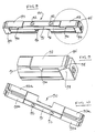
- each seat is comprised of a pair of laterally spaced devices as the one shown in FIG. 1.
- the drawings and the description relating thereto will refer only to a single device (the one on the left side). It is understood that each seat is to be fitted with a pair of said devices, laterally spaced apart and oriented substantially parallel in the longitudinal direction of the vehicle, indicated by axis y in the three-dimensional diagram near FIG. 1.
- a fixed guide 10 is rigidly fixed to the floor of the vehicle (not shown).
- Fixed guide 10 slidably supports a mobile guide 20 integral to the bottom of a seat (not shown).
- a manually operated release lever 30 is hinged at an intermediate point thereof to the mobile guide 20 by means of a pin 32.
- Pin 32 is substantially horizontal and oriented transversally in the direction of axis x in FIG. 1.
- the release lever 30, per se known, is substantially U-shaped and forms a front central portion 31 serving as a handle.
- the free end portions 33 of the handle respectively engage locking devices for normally locking the mobile guides to the fixed guides and temporarily allowing to release the mobile guides in order to change the lengthwise position of the seat. This is attained, in known manner, against the biasing action of an elastic force which tends to keep the guides mutually locked.
- Each locking device is securely anchored to its own mobile guide 10 at a side wall 21 thereof.
- the locking device comprises a support plate 60 to which there is mounted a locking hook 80.
- Hook 80 is hinged on a pin 70 rigidly fixed to the support plate 60 and oriented parallel to the guides. Hook 80 rotates centrally on pin 70 (FIG. 3).
- a concave seat 81 for engagement of the free end 33 of release lever 30, and a set of teeth 82 adapted for locking in corresponding hooking seats 11 serving as fixed hooking seats on the fixed guide 10.
- An elastic member 85 preferably in form of a spring with end portions fixed to the support plate 60, constantly urges the teeth 82 in a locking position within hooking seats 11 (shown in FIGS. 4, 5 and 12).
- the spring 85 is snap-fitted to the support plate 60.
- the two ends of the spring are at first inserted in tunnel portions 61 obtained in the support; then, the spring is pushed downwards until it passes over a stopping tooth 62 for the spring.
- FIG. 4 clearly shows the teeth 82 of locking hook 80, having three teeth.
- the central tooth is substantially wedge-shaped and forms a wall 83 inclined with respect to the longitudinal direction. Inclined wall 83 stops the vertical advancement of hook 80 during the locking motion into hooking seat 11. Owing to such a wedge-like arrangement of the hooking means, the hook takes away clearance in the lengthwise direction as it wedges itself into the seats 11 of fixed guide 10.
- a slack taking-up device 90 comprises an elongated central body 91 adapted for slidably inserting within the fixed guide 10, as shown in the section of FIG. 6.
- the central body 91 Obtained in the central body 91 are two bores 92 for accommodating one or more pins 22 for driving the mobile guide 20, to which the device 90 is rotatably mounted so as to slide as a unit therewith.
- a pair of sliding shoes 93a, 93b acting in perpendicular planes and adapted for taking away both vertical and transversal clearance between the mobile guides and the fixed guides.
- respective hinging seats 94 for rotatably accommodating the sliding shoes 93.
- the end portions 95 of the sliding shoes 93 are elastically pressed in the outward direction to contact the fixed guides 10.
- Such an elastic bias is provided by a pair of lengthwise springs 96 which pull a pair of end cams or wedges 97 towards the centre of body 91.
- Said end cams form an inclined surface 98 for each sliding shoe.
- Inclined surfaces 98 engage the sliding shoes and are so inclined and oriented as to push and extend vertically and transversally, respectively, the sliding shoes end portions 95.
- the device of the present invention further exploits conventional sliding shoes 100 fitted to the edges of the fixed guides. It will be appreciated that the two metal sections do not touch each other, whereby no unpleasant noise is generated as the position of the seat is adjusted.
- the system of the present invention tends to considerably improve the smoothness during the sliding of the guides, which has become increasingly more important for automobile manufacturers. Besides avoiding jamming during the sliding of the mobile guide, the force for shifting the seat is constant and low, as the load are equally distributed.
- the number of sliding shoes to be installed may vary between 4 and 6, i.e. 2 or 3 on each wall of the fixed guide. This ensures that in every position of the fixed guide there will always be a sufficient number of sliding shoes engaged to render the whole system steady.
- the present invention proposes to use the upper-lateral zones of the sections.
- the choice of these zones of high structural strength, weakens the guide less than the presently known systems wherein openings are usually formed in the side walls of the guide sections. This aspect provides a considerable advantage in dimensioning the system so as to pass the crash test to which the seat is subjected.
Landscapes
- Engineering & Computer Science (AREA)
- Aviation & Aerospace Engineering (AREA)
- Transportation (AREA)
- Mechanical Engineering (AREA)
- Seats For Vehicles (AREA)
- Passenger Equipment (AREA)
- Vehicle Step Arrangements And Article Storage (AREA)
Applications Claiming Priority (2)
| Application Number | Priority Date | Filing Date | Title |
|---|---|---|---|
| ITTO960506 | 1996-06-12 | ||
| IT96TO000506A IT1285414B1 (it) | 1996-06-12 | 1996-06-12 | Dispositivo di regolazione longitudinale di sedili per autoveicoli. |
Publications (2)
| Publication Number | Publication Date |
|---|---|
| EP0812721A2 true EP0812721A2 (de) | 1997-12-17 |
| EP0812721A3 EP0812721A3 (de) | 1998-12-02 |
Family
ID=11414708
Family Applications (1)
| Application Number | Title | Priority Date | Filing Date |
|---|---|---|---|
| EP97109189A Withdrawn EP0812721A3 (de) | 1996-06-12 | 1997-06-06 | Vorrichtung zum Längsverstellen von Kraftfahrzeugsitzen |
Country Status (2)
| Country | Link |
|---|---|
| EP (1) | EP0812721A3 (de) |
| IT (1) | IT1285414B1 (de) |
Cited By (3)
| Publication number | Priority date | Publication date | Assignee | Title |
|---|---|---|---|---|
| EP0947381A3 (de) * | 1998-03-31 | 2000-07-26 | Sergio Gallo | Längsverstellvorichtung für Kraftfahrzeugsitze |
| WO2000076802A1 (en) * | 1999-06-11 | 2000-12-21 | P.L. Porter Co. | System for coordinating opening and closing of multiple mechanical locks for a vehicle |
| DE102018219661B4 (de) | 2017-12-26 | 2025-09-25 | Hyundai Dymos Incorporated | Sitzschiene für ein Fahrzeug |
Family Cites Families (7)
| Publication number | Priority date | Publication date | Assignee | Title |
|---|---|---|---|---|
| US3310274A (en) * | 1965-08-09 | 1967-03-21 | Gen Motors Corp | Manual seat adjuster locking device |
| FR2259719B1 (de) * | 1974-01-31 | 1978-12-29 | Cousin Cie Ets A & M Freres | |
| GB1537291A (en) * | 1976-01-14 | 1978-12-29 | Turner Ltd H | Seat slides |
| FR2445779A2 (fr) * | 1979-01-02 | 1980-08-01 | Faure Bertrand | Perfectionnements aux glissieres de support de siege |
| JPS57194121A (en) * | 1981-05-22 | 1982-11-29 | Oi Seisakusho Co Ltd | Seat slide of automobile |
| DE3927736A1 (de) * | 1989-08-23 | 1991-02-28 | Keiper Recaro Gmbh Co | Verriegelungsvorrichtung fuer ein schienenpaar eines fahrzeugsitzes |
| US5234189A (en) * | 1992-04-23 | 1993-08-10 | Hoover Universal, Inc. | Seat assembly with irreversible pawl adjusting latch mechanism |
-
1996
- 1996-06-12 IT IT96TO000506A patent/IT1285414B1/it active IP Right Grant
-
1997
- 1997-06-06 EP EP97109189A patent/EP0812721A3/de not_active Withdrawn
Cited By (3)
| Publication number | Priority date | Publication date | Assignee | Title |
|---|---|---|---|---|
| EP0947381A3 (de) * | 1998-03-31 | 2000-07-26 | Sergio Gallo | Längsverstellvorichtung für Kraftfahrzeugsitze |
| WO2000076802A1 (en) * | 1999-06-11 | 2000-12-21 | P.L. Porter Co. | System for coordinating opening and closing of multiple mechanical locks for a vehicle |
| DE102018219661B4 (de) | 2017-12-26 | 2025-09-25 | Hyundai Dymos Incorporated | Sitzschiene für ein Fahrzeug |
Also Published As
| Publication number | Publication date |
|---|---|
| ITTO960506A0 (de) | 1996-06-12 |
| IT1285414B1 (it) | 1998-06-03 |
| EP0812721A3 (de) | 1998-12-02 |
| ITTO960506A1 (it) | 1997-12-12 |
Similar Documents
| Publication | Publication Date | Title |
|---|---|---|
| KR100610431B1 (ko) | 자동차용 시트 슬라이드 장치 | |
| CN111132871B (zh) | 用于在碰撞情况下使车辆座椅减速的车辆座椅的座椅导轨模块 | |
| EP0617675B1 (de) | Extrudierte gleitschiene für kraftfahrzeugsitze | |
| CN109476244B (zh) | 纵向调节器和车辆座椅 | |
| US4068887A (en) | Seat mountings | |
| US4470618A (en) | Adjustable seat belt anchorage | |
| KR100559459B1 (ko) | 자동차용 시트레일 로킹장치 | |
| EP1241060A1 (de) | Dreipunkt-Sicherheitsgurtsystem | |
| GB1589126A (en) | Vehicle seats | |
| US6719369B1 (en) | Child seat arrangement on a motor vehicle seat | |
| KR20140111311A (ko) | 진입 간편화 기능을 갖는 차량 시트용 잠금 해제 장치 및 잠금 해제 장치의 작동 방법 | |
| JP2001187538A (ja) | シートスライド装置 | |
| KR100899906B1 (ko) | 차량용 시트의 슬라이드 장치 | |
| GB2219933A (en) | Seat slide assembly characterised by the configuration of the interengaging members | |
| EP0812721A2 (de) | Vorrichtung zum Längsverstellen von Kraftfahrzeugsitzen | |
| KR20230155461A (ko) | 차량 좌석의 길이방향 조정을 위한 조정 디바이스 및 이를 위한 부가적인 잠금장치 | |
| JPH0231967A (ja) | シートスライド装置 | |
| US3469812A (en) | Adjustable vehicle seat mounting | |
| EP4556304A1 (de) | Lastabsorptionsvorrichtung zur verwendung mit einem fahrzeugsitz, fahrzeuginsassenschutzsystem mit solch einer vorrichtung und verfahren zum betrieb eines systems | |
| US10377339B2 (en) | Seatbelt tensioning assembly | |
| JP2002144931A (ja) | シートスライド装置 | |
| KR970000212Y1 (ko) | 자동차용 시트 트랙(seat track) | |
| KR940005868B1 (ko) | 시트 슬라이드 장치 | |
| KR970001465Y1 (ko) | 자동차용 시트 트랙 | |
| CA2474278A1 (en) | Automotive seat track having vertically adjustable bearings |
Legal Events
| Date | Code | Title | Description |
|---|---|---|---|
| PUAI | Public reference made under article 153(3) epc to a published international application that has entered the european phase |
Free format text: ORIGINAL CODE: 0009012 |
|
| AK | Designated contracting states |
Kind code of ref document: A2 Designated state(s): AT BE CH DE DK ES FI FR GB GR IE IT LI LU MC NL PT SE |
|
| PUAL | Search report despatched |
Free format text: ORIGINAL CODE: 0009013 |
|
| AK | Designated contracting states |
Kind code of ref document: A3 Designated state(s): AT BE CH DE DK ES FI FR GB GR IE IT LI LU MC NL PT SE |
|
| AKX | Designation fees paid | ||
| STAA | Information on the status of an ep patent application or granted ep patent |
Free format text: STATUS: THE APPLICATION IS DEEMED TO BE WITHDRAWN |
|
| 18D | Application deemed to be withdrawn |
Effective date: 19990603 |
|
| REG | Reference to a national code |
Ref country code: DE Ref legal event code: 8566 |