EP0812935A2 - Procédé et dispositif de commande du refoulement de fluides avec une cellule de génération de gaz et un multiplicateur de débit - Google Patents
Procédé et dispositif de commande du refoulement de fluides avec une cellule de génération de gaz et un multiplicateur de débit Download PDFInfo
- Publication number
- EP0812935A2 EP0812935A2 EP97107720A EP97107720A EP0812935A2 EP 0812935 A2 EP0812935 A2 EP 0812935A2 EP 97107720 A EP97107720 A EP 97107720A EP 97107720 A EP97107720 A EP 97107720A EP 0812935 A2 EP0812935 A2 EP 0812935A2
- Authority
- EP
- European Patent Office
- Prior art keywords
- decomposition
- gas
- cell
- gas development
- liquid
- Prior art date
- Legal status (The legal status is an assumption and is not a legal conclusion. Google has not performed a legal analysis and makes no representation as to the accuracy of the status listed.)
- Granted
Links
- 238000000034 method Methods 0.000 title claims abstract description 13
- 239000012530 fluid Substances 0.000 title abstract description 5
- 239000007789 gas Substances 0.000 claims abstract description 46
- 238000000354 decomposition reaction Methods 0.000 claims abstract description 38
- 239000007788 liquid Substances 0.000 claims abstract description 32
- 239000003054 catalyst Substances 0.000 claims abstract description 22
- UFHFLCQGNIYNRP-UHFFFAOYSA-N Hydrogen Chemical compound [H][H] UFHFLCQGNIYNRP-UHFFFAOYSA-N 0.000 claims abstract description 17
- 239000001257 hydrogen Substances 0.000 claims abstract description 17
- 229910052739 hydrogen Inorganic materials 0.000 claims abstract description 17
- 239000000843 powder Substances 0.000 claims abstract description 10
- 229920001343 polytetrafluoroethylene Polymers 0.000 claims abstract description 8
- 239000004810 polytetrafluoroethylene Substances 0.000 claims abstract description 8
- 239000012528 membrane Substances 0.000 claims abstract description 7
- QVGXLLKOCUKJST-UHFFFAOYSA-N atomic oxygen Chemical compound [O] QVGXLLKOCUKJST-UHFFFAOYSA-N 0.000 claims abstract description 6
- 239000001301 oxygen Substances 0.000 claims abstract description 6
- 229910052760 oxygen Inorganic materials 0.000 claims abstract description 6
- 239000000126 substance Substances 0.000 claims abstract description 6
- 230000009969 flowable effect Effects 0.000 claims abstract 8
- 239000006072 paste Substances 0.000 claims abstract 3
- 238000003421 catalytic decomposition reaction Methods 0.000 claims abstract 2
- 230000003197 catalytic effect Effects 0.000 claims abstract 2
- 230000032258 transport Effects 0.000 claims abstract 2
- 230000002209 hydrophobic effect Effects 0.000 claims description 8
- XLYOFNOQVPJJNP-UHFFFAOYSA-N water Chemical compound O XLYOFNOQVPJJNP-UHFFFAOYSA-N 0.000 claims description 7
- MHAJPDPJQMAIIY-UHFFFAOYSA-N Hydrogen peroxide Chemical compound OO MHAJPDPJQMAIIY-UHFFFAOYSA-N 0.000 claims description 6
- 230000001105 regulatory effect Effects 0.000 claims description 6
- 229910052751 metal Inorganic materials 0.000 claims description 4
- 239000002184 metal Substances 0.000 claims description 4
- 239000011148 porous material Substances 0.000 claims description 3
- ZLMJMSJWJFRBEC-UHFFFAOYSA-N Potassium Chemical compound [K] ZLMJMSJWJFRBEC-UHFFFAOYSA-N 0.000 claims description 2
- 238000003860 storage Methods 0.000 claims description 2
- -1 polytetrafluoroethylene Polymers 0.000 claims 2
- BTBUEUYNUDRHOZ-UHFFFAOYSA-N Borate Chemical compound [O-]B([O-])[O-] BTBUEUYNUDRHOZ-UHFFFAOYSA-N 0.000 claims 1
- DGAQECJNVWCQMB-PUAWFVPOSA-M Ilexoside XXIX Chemical compound C[C@@H]1CC[C@@]2(CC[C@@]3(C(=CC[C@H]4[C@]3(CC[C@@H]5[C@@]4(CC[C@@H](C5(C)C)OS(=O)(=O)[O-])C)C)[C@@H]2[C@]1(C)O)C)C(=O)O[C@H]6[C@@H]([C@H]([C@@H]([C@H](O6)CO)O)O)O.[Na+] DGAQECJNVWCQMB-PUAWFVPOSA-M 0.000 claims 1
- WHXSMMKQMYFTQS-UHFFFAOYSA-N Lithium Chemical compound [Li] WHXSMMKQMYFTQS-UHFFFAOYSA-N 0.000 claims 1
- 229910052783 alkali metal Inorganic materials 0.000 claims 1
- 150000001340 alkali metals Chemical class 0.000 claims 1
- 229910052744 lithium Inorganic materials 0.000 claims 1
- 229910052700 potassium Inorganic materials 0.000 claims 1
- 239000011591 potassium Substances 0.000 claims 1
- 229910052708 sodium Inorganic materials 0.000 claims 1
- 239000011734 sodium Substances 0.000 claims 1
- 238000006073 displacement reaction Methods 0.000 abstract 1
- 239000000243 solution Substances 0.000 description 15
- PXHVJJICTQNCMI-UHFFFAOYSA-N Nickel Chemical compound [Ni] PXHVJJICTQNCMI-UHFFFAOYSA-N 0.000 description 14
- 239000007868 Raney catalyst Substances 0.000 description 9
- 229910000564 Raney nickel Inorganic materials 0.000 description 9
- NVIFVTYDZMXWGX-UHFFFAOYSA-N sodium metaborate Chemical compound [Na+].[O-]B=O NVIFVTYDZMXWGX-UHFFFAOYSA-N 0.000 description 7
- BQCADISMDOOEFD-UHFFFAOYSA-N Silver Chemical compound [Ag] BQCADISMDOOEFD-UHFFFAOYSA-N 0.000 description 5
- QGZKDVFQNNGYKY-UHFFFAOYSA-N Ammonia Chemical compound N QGZKDVFQNNGYKY-UHFFFAOYSA-N 0.000 description 4
- IJGRMHOSHXDMSA-UHFFFAOYSA-N Atomic nitrogen Chemical compound N#N IJGRMHOSHXDMSA-UHFFFAOYSA-N 0.000 description 4
- OKTJSMMVPCPJKN-UHFFFAOYSA-N Carbon Chemical compound [C] OKTJSMMVPCPJKN-UHFFFAOYSA-N 0.000 description 4
- XEEYBQQBJWHFJM-UHFFFAOYSA-N Iron Chemical compound [Fe] XEEYBQQBJWHFJM-UHFFFAOYSA-N 0.000 description 4
- 229910052709 silver Inorganic materials 0.000 description 4
- 239000004332 silver Substances 0.000 description 4
- HEMHJVSKTPXQMS-UHFFFAOYSA-M Sodium hydroxide Chemical compound [OH-].[Na+] HEMHJVSKTPXQMS-UHFFFAOYSA-M 0.000 description 3
- 239000003929 acidic solution Substances 0.000 description 3
- 239000000463 material Substances 0.000 description 3
- 239000000203 mixture Substances 0.000 description 3
- MYMOFIZGZYHOMD-UHFFFAOYSA-N Dioxygen Chemical compound O=O MYMOFIZGZYHOMD-UHFFFAOYSA-N 0.000 description 2
- OAKJQQAXSVQMHS-UHFFFAOYSA-N Hydrazine Chemical compound NN OAKJQQAXSVQMHS-UHFFFAOYSA-N 0.000 description 2
- 239000005909 Kieselgur Substances 0.000 description 2
- KDLHZDBZIXYQEI-UHFFFAOYSA-N Palladium Chemical compound [Pd] KDLHZDBZIXYQEI-UHFFFAOYSA-N 0.000 description 2
- VYPSYNLAJGMNEJ-UHFFFAOYSA-N Silicium dioxide Chemical compound O=[Si]=O VYPSYNLAJGMNEJ-UHFFFAOYSA-N 0.000 description 2
- 229910021529 ammonia Inorganic materials 0.000 description 2
- 239000007864 aqueous solution Substances 0.000 description 2
- 238000010276 construction Methods 0.000 description 2
- 238000006356 dehydrogenation reaction Methods 0.000 description 2
- 229910001882 dioxygen Inorganic materials 0.000 description 2
- 230000000694 effects Effects 0.000 description 2
- 239000003925 fat Substances 0.000 description 2
- 238000002347 injection Methods 0.000 description 2
- 239000007924 injection Substances 0.000 description 2
- 229910052742 iron Inorganic materials 0.000 description 2
- NUJOXMJBOLGQSY-UHFFFAOYSA-N manganese dioxide Chemical compound O=[Mn]=O NUJOXMJBOLGQSY-UHFFFAOYSA-N 0.000 description 2
- 150000002739 metals Chemical class 0.000 description 2
- 229910052759 nickel Inorganic materials 0.000 description 2
- 229910052757 nitrogen Inorganic materials 0.000 description 2
- TWNQGVIAIRXVLR-UHFFFAOYSA-N oxo(oxoalumanyloxy)alumane Chemical compound O=[Al]O[Al]=O TWNQGVIAIRXVLR-UHFFFAOYSA-N 0.000 description 2
- BASFCYQUMIYNBI-UHFFFAOYSA-N platinum Chemical compound [Pt] BASFCYQUMIYNBI-UHFFFAOYSA-N 0.000 description 2
- KWYUFKZDYYNOTN-UHFFFAOYSA-M potassium hydroxide Inorganic materials [OH-].[K+] KWYUFKZDYYNOTN-UHFFFAOYSA-M 0.000 description 2
- 229910000838 Al alloy Inorganic materials 0.000 description 1
- 229910000990 Ni alloy Inorganic materials 0.000 description 1
- HCHKCACWOHOZIP-UHFFFAOYSA-N Zinc Chemical compound [Zn] HCHKCACWOHOZIP-UHFFFAOYSA-N 0.000 description 1
- 238000010521 absorption reaction Methods 0.000 description 1
- 238000007792 addition Methods 0.000 description 1
- 239000003513 alkali Substances 0.000 description 1
- 150000008044 alkali metal hydroxides Chemical class 0.000 description 1
- 239000012670 alkaline solution Substances 0.000 description 1
- 229910052782 aluminium Inorganic materials 0.000 description 1
- XAGFODPZIPBFFR-UHFFFAOYSA-N aluminium Chemical compound [Al] XAGFODPZIPBFFR-UHFFFAOYSA-N 0.000 description 1
- 230000000903 blocking effect Effects 0.000 description 1
- 230000015556 catabolic process Effects 0.000 description 1
- 239000003795 chemical substances by application Substances 0.000 description 1
- 229910017052 cobalt Inorganic materials 0.000 description 1
- 239000010941 cobalt Substances 0.000 description 1
- GUTLYIVDDKVIGB-UHFFFAOYSA-N cobalt atom Chemical compound [Co] GUTLYIVDDKVIGB-UHFFFAOYSA-N 0.000 description 1
- 229910052802 copper Inorganic materials 0.000 description 1
- 230000008021 deposition Effects 0.000 description 1
- 238000009826 distribution Methods 0.000 description 1
- 239000003792 electrolyte Substances 0.000 description 1
- 230000002706 hydrostatic effect Effects 0.000 description 1
- 238000001802 infusion Methods 0.000 description 1
- 238000004519 manufacturing process Methods 0.000 description 1
- 238000002156 mixing Methods 0.000 description 1
- 229910052763 palladium Inorganic materials 0.000 description 1
- 230000000737 periodic effect Effects 0.000 description 1
- 239000004033 plastic Substances 0.000 description 1
- 229910052697 platinum Inorganic materials 0.000 description 1
- JVUYWILPYBCNNG-UHFFFAOYSA-N potassium;oxido(oxo)borane Chemical compound [K+].[O-]B=O JVUYWILPYBCNNG-UHFFFAOYSA-N 0.000 description 1
- 239000007787 solid Substances 0.000 description 1
- 230000008961 swelling Effects 0.000 description 1
- 238000005496 tempering Methods 0.000 description 1
- 229910052725 zinc Inorganic materials 0.000 description 1
- 239000011701 zinc Substances 0.000 description 1
Images
Classifications
-
- F—MECHANICAL ENGINEERING; LIGHTING; HEATING; WEAPONS; BLASTING
- F04—POSITIVE - DISPLACEMENT MACHINES FOR LIQUIDS; PUMPS FOR LIQUIDS OR ELASTIC FLUIDS
- F04B—POSITIVE-DISPLACEMENT MACHINES FOR LIQUIDS; PUMPS
- F04B17/00—Pumps characterised by combination with, or adaptation to, specific driving engines or motors
-
- B—PERFORMING OPERATIONS; TRANSPORTING
- B01—PHYSICAL OR CHEMICAL PROCESSES OR APPARATUS IN GENERAL
- B01J—CHEMICAL OR PHYSICAL PROCESSES, e.g. CATALYSIS OR COLLOID CHEMISTRY; THEIR RELEVANT APPARATUS
- B01J4/00—Feed or outlet devices; Feed or outlet control devices
- B01J4/001—Feed or outlet devices as such, e.g. feeding tubes
-
- B—PERFORMING OPERATIONS; TRANSPORTING
- B01—PHYSICAL OR CHEMICAL PROCESSES OR APPARATUS IN GENERAL
- B01J—CHEMICAL OR PHYSICAL PROCESSES, e.g. CATALYSIS OR COLLOID CHEMISTRY; THEIR RELEVANT APPARATUS
- B01J7/00—Apparatus for generating gases
- B01J7/02—Apparatus for generating gases by wet methods
Definitions
- the hydrogen is generated by deposition on a cathode with a hydrophilic / hydropobic pore structure.
- Zinc serves as the anode.
- Electrolyte is potassium or sodium hydroxide solution. Limiting the electrochemical processes on the electrodes also limits the gas evolution. This limits the cell flow and thus the highest possible gas generation rate, but also the maximum delivery rate of the paste or liquid. Larger gas development cells can be built and used for higher production rates or cells can be electrically connected in series in a known manner for parallel gas generation, but this is associated with increased costs.
- the object of this invention is to increase and multiply the gas generation rate.
- hydrogen can be developed by contacting alkali boranate, for example potassium boranate KBH 4 or sodium boranate NaBH 4 in aqueous solution, with dehydrogenation catalysts.
- From 1 g of NaBH 4 2370 ccm of hydrogen are produced during the decomposition.
- With a 10% solution about 100 mg NaBH 4 are contained in 1 ccm solution; 237 ccm of hydrogen are produced from this.
- the decomposition is inhibited in alkaline solution, accelerated in acidic solution.
- Raney nickel is suitable for reasons of price that can be obtained from a nickel / aluminum alloy by dissolving out the aluminum with the aid of an alkali metal hydroxide solution.
- This catalyst is particularly active if it contains additions of iron (10% by weight) or cobalt. It is also advantageous to depyrophorize the Raney nickel and to stabilize it by tempering.
- a gas stream can also be achieved by using an aqueous hydrazine solution as the decomposable liquid.
- Raney nickel decomposition into hydrogen and nitrogen is preferred. If Raney nickel contains 10% iron, the catalyst splits into a very hot ammonia / nitrogen mixture.
- Oxygen gas can be generated by decomposing hydrogen peroxide.
- the decomposable liquid H 2 O 2 in aqueous solution is passed over one of the known decomposition catalysts and is broken down into water and oxygen gas.
- Silver is preferably used as a catalyst and preferably in a fine distribution as ranesilver, as molecular silver powder or silver deposited on porous support materials (activated carbon, aluminum oxide, manganese dioxide).
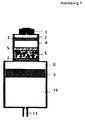
- Fig. 1 shows an embodiment of the claimed device.
- the first stage consists of components 1, 2, 3, 4 and 5
- the second stage consists of components 6, 7, 8, 9, 10 and 11.
- 1 is the gas development cell, which according to DE-PS 35 32 335.3 Hydrogen or oxygen generated at a rate determined by the cell current.
- 1 also contains the construction elements for setting the cell current such as the load resistance and, if applicable, an auxiliary power source as a symbol.
- 1 also stands symbolically for several gas development cells, which are electrically connected in series for the gas flow in parallel.
- the gas cell 1 delivers the gas into the working space 2 in the first delivery cylinder and thus displaces the piston 3 into the delivery space 4, which contains the decomposition liquid.
- valve 5 Via the valve 5, which in this case is supposed to be a coarse-pored hydrophobic disk, the liquid is conveyed into the reactor space 6 of the second stage, which contains the decomposition catalyst for the liquid that can be decomposed under gas evolution.
- the valve 7 is a fine-pored, hydrophobic disk, which blocks the liquid but allows the gas generated in 6 to enter the gas space of the second delivery cylinder.
- a gas pressure now builds up here, which displaces the second piston 9 and presses out the conveyed material located in the conveying space 10 at 11 as intended.
- Valve 5 a coarse-pored hydrophobic disk in FIG. 1, is intended to keep the liquid for the decomposer out of the decomposition chamber 6 as long as no gas pressure has built up in the gas development cell. Thereafter, it should ensure a flow that is as uniform as possible so that no decomposition impacts occur in 6.
- a coarse-pored, hydrophobic disc 5 retains the decomposition liquid in 4 and can only be overcome by the liquid if its hydrostatic pressure compared to the pressure in 6 can overcome the capillary depression in the pores. In this sense, the device also works when the liquid in 4 is in a sponge, which is expressed by the action of the piston 3. The sponge increases the safety of the decomposition liquid.
- the decomposition liquid in 4 need not be decomposable itself; it suffices if it initiates the decomposition of the solid substance or liquid located there when it flows into the reactor space 6.
- sodium boranate powder - possibly mixed with a catalyst - can be stored in the reactor room.
- the boranate powder is dissolved, reaches the catalyst and is decomposed.
- the decomposition effect can also be influenced by the choice of the pH value of the decomposition liquid, since acidic solutions reduce the stability of the boranate.
- the possible water absorption by sodium boranate in 6 via the hydrophobic valve disk 5 has a disadvantageous effect on the stability of sodium boranate during the storage period. It can be prevented with a valve 5 which, in the event of overpressure in 4, opens the way into the reactor 6 for the decomposition liquid, but which is impermeable to water vapor. This task is solved by a space membrane which blocks water vapor, the blocking effect of which is no longer required after the device is activated.
- a hydrogen development cell the size of the often used hearing aid cell with a diameter of 6.5 mm and a height of 5.6 mm provides a short-circuit resistance of 2.2 mA at 130 ⁇ ; this flow causes a flow of the decomposition liquid of 0.92 cm 3 / h. If the decomposer solution consists of 10% sodium boranate solution, the amount of hydrogen is multiplied from 0.92 cm 3 / h of the gas cell to 218 cm 3 / h of the decomposer.
- the amount of catalyst in the reactor must depend on the desired output.
- a catalyst amount of 100 mg of Raney nickel is sufficient for the example mentioned.
- double or triple the amount will be installed to increase the functional reliability, depending on the construction of the catalyst bed. It is therefore advantageous to punch round blanks as a catalyst bed from a porous gas electrode according to EP-PS 0 144 002 B1, which contains about 1 mg / cm 2 Raney nickel bonded with PTFE onto a Cu or Ni mesh. The metal mesh then distributes the heat of decomposition, while the PTFE bond of the catalyst reduces grain breakdown.
- water-binding substances such as diatomaceous earth, swelling agents or plastic sponges can be introduced into the reactor space, which are intended to prevent the fine-pored hydrophobic membrane from being blocked by a liquid film for the passage of gas.
- 0.1 g of NaBH 4 powder was mixed together with 0.2 g of dry Raney nickel and introduced into the reactor chamber 6.
- the decomposition liquid consisted of weakly alkaline buffered water. The decomposition reaction occurred with the injection of the decomposition solution from 4 into 6. You can also use one for filling 6 Use a mixture that is produced by mixing boranate powder with Raney nickel and PTFE powder in a high-speed mixer.
- the conveyor device according to the invention operated by decomposition of H 2 0 2 solution
- an oxygen development cell is used for safety reasons, although the first stage can also be driven with hydrogen.
- the decomposing liquid is a 30% aqueous H 2 O 2 solution. From this, 100 Ncm 3 gas are developed per 1 g of solution with a silver catalyst. When using a 70% solution, it is 230 Ncm 3 gas.
- a catalyst circular blanks can be found in column 3 of DE-OS 37 10 168 A1 highly active silver electrode ".
- this electrode consists of Ag 2 O before it is reduced, it can also be installed in this state, since the Ag 2 O is reduced by H 2 O 2 and the oxygen released thereby increases the delivery rate the measures for the embodiment of the invention described for the decomposition of boranate solution can be transferred to this variant, only the gas cell stream which triggers the decomposition process has to be doubled compared to the hydrogen development cell in order to generate the same gas volume flow.
Landscapes
- Chemical & Material Sciences (AREA)
- Engineering & Computer Science (AREA)
- Organic Chemistry (AREA)
- Chemical Kinetics & Catalysis (AREA)
- Mechanical Engineering (AREA)
- General Engineering & Computer Science (AREA)
- Catalysts (AREA)
- Feeding, Discharge, Calcimining, Fusing, And Gas-Generation Devices (AREA)
- Fuel Cell (AREA)
Applications Claiming Priority (2)
| Application Number | Priority Date | Filing Date | Title |
|---|---|---|---|
| DE19619376 | 1996-05-14 | ||
| DE19619376A DE19619376A1 (de) | 1996-05-14 | 1996-05-14 | Verfahren und Vorrichtung zur gesteuerten oder geregelten Förderung von fließfähigen Medien mit einer Gasentwicklungszelle und einem Strömungsvervielfacher |
Publications (3)
| Publication Number | Publication Date |
|---|---|
| EP0812935A2 true EP0812935A2 (fr) | 1997-12-17 |
| EP0812935A3 EP0812935A3 (fr) | 1998-12-09 |
| EP0812935B1 EP0812935B1 (fr) | 2002-08-14 |
Family
ID=7794261
Family Applications (1)
| Application Number | Title | Priority Date | Filing Date |
|---|---|---|---|
| EP97107720A Expired - Lifetime EP0812935B1 (fr) | 1996-05-14 | 1997-05-12 | Procédé et dispositif de commande du refoulement de fluides avec une cellule de génération de gaz et un multiplicateur de débit |
Country Status (3)
| Country | Link |
|---|---|
| US (1) | US5871632A (fr) |
| EP (1) | EP0812935B1 (fr) |
| DE (2) | DE19619376A1 (fr) |
Families Citing this family (1)
| Publication number | Priority date | Publication date | Assignee | Title |
|---|---|---|---|---|
| DE10109274A1 (de) * | 2001-02-24 | 2002-09-26 | Dornier Gmbh | Vorrichtung zur Verminderung der IR-Zielsignatur von Luftfahrzeugen |
Citations (3)
| Publication number | Priority date | Publication date | Assignee | Title |
|---|---|---|---|---|
| DE3710168A1 (de) | 1987-03-27 | 1988-10-13 | Varta Batterie | Verfahren zur herstellung einer kunststoffgebundenen gasdiffusionselektrode mit metallischen elektrokatalysatoren |
| EP0144002B1 (fr) | 1983-11-28 | 1989-01-18 | VARTA Batterie Aktiengesellschaft | Electrode poreuse à gaz |
| DE3532335C2 (fr) | 1985-09-11 | 1989-11-23 | August Prof. Dr. 6233 Kelkheim De Winsel |
Family Cites Families (6)
| Publication number | Priority date | Publication date | Assignee | Title |
|---|---|---|---|---|
| DE3643352A1 (de) * | 1986-12-18 | 1988-06-23 | Satzinger Gebhard Gmbh Co | Einrichtung zur elektrochemischen erzeugung von gasen zum transport von fluiden medien |
| ATE126339T1 (de) * | 1988-03-16 | 1995-08-15 | Max Wyssmann | Schmierstoffgeber. |
| US5242565A (en) * | 1989-07-10 | 1993-09-07 | August Winsel | Device for electrochemical generation of gases for the transportation of fluids and similar mediums |
| US5423454A (en) * | 1992-08-19 | 1995-06-13 | Lippman, Deceased; Lawrence G. | Method of propellant gas generation |
| US5744014A (en) * | 1994-09-06 | 1998-04-28 | Ceramatec, Inc. | Storage stable electrolytic gas generator for fluid dispensing applications |
| DE4446463C1 (de) * | 1994-12-28 | 1996-02-08 | Satzinger Gmbh & Co | Schmierstoffspender zur gasgesteuerten Abgabe eines Schmierstoffes |
-
1996
- 1996-05-14 DE DE19619376A patent/DE19619376A1/de not_active Withdrawn
-
1997
- 1997-05-12 EP EP97107720A patent/EP0812935B1/fr not_active Expired - Lifetime
- 1997-05-12 DE DE59707949T patent/DE59707949D1/de not_active Expired - Fee Related
- 1997-05-14 US US08/856,629 patent/US5871632A/en not_active Expired - Fee Related
Patent Citations (3)
| Publication number | Priority date | Publication date | Assignee | Title |
|---|---|---|---|---|
| EP0144002B1 (fr) | 1983-11-28 | 1989-01-18 | VARTA Batterie Aktiengesellschaft | Electrode poreuse à gaz |
| DE3532335C2 (fr) | 1985-09-11 | 1989-11-23 | August Prof. Dr. 6233 Kelkheim De Winsel | |
| DE3710168A1 (de) | 1987-03-27 | 1988-10-13 | Varta Batterie | Verfahren zur herstellung einer kunststoffgebundenen gasdiffusionselektrode mit metallischen elektrokatalysatoren |
Also Published As
| Publication number | Publication date |
|---|---|
| US5871632A (en) | 1999-02-16 |
| EP0812935A3 (fr) | 1998-12-09 |
| DE19619376A1 (de) | 1997-11-20 |
| DE59707949D1 (de) | 2002-09-19 |
| EP0812935B1 (fr) | 2002-08-14 |
Similar Documents
| Publication | Publication Date | Title |
|---|---|---|
| DE2626294C3 (de) | Implantierbare Dosiereinrichtung | |
| DE3532335A1 (de) | Galvanische zelle zur entwicklung von wasserstoff bzw. sauerstoff | |
| DE3621846C2 (fr) | ||
| DE2930056C2 (fr) | ||
| DE2125576B2 (de) | Verfahren zur Erzeugung von elek tnschem Strom durch elektrochemische Oxydation von Zink mit Hilfe einer positiven Sauerstoff oder Metalloxid elektrode und Vorrichtung zu seiner Durch fuhrung | |
| DE3710168A1 (de) | Verfahren zur herstellung einer kunststoffgebundenen gasdiffusionselektrode mit metallischen elektrokatalysatoren | |
| EP0343157B1 (fr) | Installation pour la production electrochimique de gaz pour le transport de fluides | |
| EP1402587A2 (fr) | Procede pour la production d'electrodes a diffusion gazeuse | |
| DE69130167T2 (de) | Katalytische rekombination von wasserstoff in alkalischen batterien | |
| EP0812935B1 (fr) | Procédé et dispositif de commande du refoulement de fluides avec une cellule de génération de gaz et un multiplicateur de débit | |
| DE1771420A1 (de) | Aufladbares Brennstoffelement | |
| DE1116287B (de) | Gas-Diffusions-Elektroden fuer Brennstoff-Elemente und Verfahren zu ihrer Herstellung | |
| DE1074015B (de) | Verfahren zur Eir stellung der Aktivität von aus Raney Metall bestehenden oder Raney Metall enthaltenden Katalysatoren | |
| DE1086768B (de) | Brennstoffelement zur Gewinnung elektrischer Energie durch direkte Umsetzung gasfoermiger Brennstoffe mit oxydierenden Gasen | |
| DE1542565B2 (de) | Verfahren zur erzeugung von reaktionsgasen fuer den betrieb galvanischer brennstoffelemente | |
| DE3338724A1 (de) | Batterie aus redoxzellen | |
| DE3711714C2 (fr) | ||
| DE1667346A1 (de) | Vorrichtung zur automatischen Nachfuehrung von Fluessigkeiten an ein Katalysatorbett | |
| DE1542565C (de) | Verfahren zur Erzeugung von Reaktions gasen fur den Betrieb galvanischer Brenn Stoffelemente | |
| DE1071789B (de) | Verfahren zur e'lektrochemliscben Oxydation von Ko'hlenmonoxyd oder Kohlenmonoxyd-Gemisch'en in Brennstoffelementen mit wäßrigen alkalischen Elektrolyten | |
| AT279697B (de) | Vorrichtung zum automatischen Nachführung von an einem Katalysator unter Gasbildung zersetzbaren, flüssigen oder gelösten Substanzen aus einem Vorratsbehälter mit vorgebbarem Förderdruck an einen Katalysatormaterial enthaltenden Zersetzer | |
| DE2504194C3 (de) | Verfahren zur Herstellung von aus einer verfestigten katalytischen Pulversubstanz und einem Kunststoffbinder bestehenden dünnen, großflächigen Elektrodenschichten für Brennstoffzellen und Vorrichtung zur Durchführung des Verfahrens | |
| DE1671985C (de) | Verfahren und Vorrichtung zur automatischen Nachführung von katalytisch zersetzbaren Flüssigkeiten an die Katalysatorelektrode in einem Brennstoffelement | |
| AT206026B (de) | Katalysator-Sieb-Elektrode zur Elektrochemischen Ausnutzung aktiver Gase in Brennstoffelementen | |
| DE1671982C (de) | Brennstoffelement oder batterie fur kontinuierlichen Betrieb |
Legal Events
| Date | Code | Title | Description |
|---|---|---|---|
| PUAI | Public reference made under article 153(3) epc to a published international application that has entered the european phase |
Free format text: ORIGINAL CODE: 0009012 |
|
| AK | Designated contracting states |
Kind code of ref document: A2 Designated state(s): DE FR GB |
|
| RBV | Designated contracting states (corrected) |
Designated state(s): DE FR GB |
|
| PUAL | Search report despatched |
Free format text: ORIGINAL CODE: 0009013 |
|
| AK | Designated contracting states |
Kind code of ref document: A3 Designated state(s): DE FR GB |
|
| 17P | Request for examination filed |
Effective date: 19990522 |
|
| GRAG | Despatch of communication of intention to grant |
Free format text: ORIGINAL CODE: EPIDOS AGRA |
|
| GRAG | Despatch of communication of intention to grant |
Free format text: ORIGINAL CODE: EPIDOS AGRA |
|
| GRAH | Despatch of communication of intention to grant a patent |
Free format text: ORIGINAL CODE: EPIDOS IGRA |
|
| 17Q | First examination report despatched |
Effective date: 20020102 |
|
| GRAH | Despatch of communication of intention to grant a patent |
Free format text: ORIGINAL CODE: EPIDOS IGRA |
|
| GRAA | (expected) grant |
Free format text: ORIGINAL CODE: 0009210 |
|
| AK | Designated contracting states |
Kind code of ref document: B1 Designated state(s): DE FR GB |
|
| PG25 | Lapsed in a contracting state [announced via postgrant information from national office to epo] |
Ref country code: GB Free format text: LAPSE BECAUSE OF FAILURE TO SUBMIT A TRANSLATION OF THE DESCRIPTION OR TO PAY THE FEE WITHIN THE PRESCRIBED TIME-LIMIT Effective date: 20020814 Ref country code: FR Free format text: LAPSE BECAUSE OF NON-PAYMENT OF DUE FEES Effective date: 20020814 |
|
| REG | Reference to a national code |
Ref country code: GB Ref legal event code: FG4D Free format text: NOT ENGLISH |
|
| REF | Corresponds to: |
Ref document number: 59707949 Country of ref document: DE Date of ref document: 20020919 |
|
| GBV | Gb: ep patent (uk) treated as always having been void in accordance with gb section 77(7)/1977 [no translation filed] |
Effective date: 20020814 |
|
| PLBE | No opposition filed within time limit |
Free format text: ORIGINAL CODE: 0009261 |
|
| STAA | Information on the status of an ep patent application or granted ep patent |
Free format text: STATUS: NO OPPOSITION FILED WITHIN TIME LIMIT |
|
| 26N | No opposition filed |
Effective date: 20030515 |
|
| PGFP | Annual fee paid to national office [announced via postgrant information from national office to epo] |
Ref country code: DE Payment date: 20060519 Year of fee payment: 10 |
|
| PG25 | Lapsed in a contracting state [announced via postgrant information from national office to epo] |
Ref country code: DE Free format text: LAPSE BECAUSE OF NON-PAYMENT OF DUE FEES Effective date: 20071201 |