EP0812979A1 - Machine de creusement de tunnels et procédé - Google Patents
Machine de creusement de tunnels et procédé Download PDFInfo
- Publication number
- EP0812979A1 EP0812979A1 EP97201789A EP97201789A EP0812979A1 EP 0812979 A1 EP0812979 A1 EP 0812979A1 EP 97201789 A EP97201789 A EP 97201789A EP 97201789 A EP97201789 A EP 97201789A EP 0812979 A1 EP0812979 A1 EP 0812979A1
- Authority
- EP
- European Patent Office
- Prior art keywords
- support structure
- machine
- support
- tunnel
- gripper
- Prior art date
- Legal status (The legal status is an assumption and is not a legal conclusion. Google has not performed a legal analysis and makes no representation as to the accuracy of the status listed.)
- Ceased
Links
Images







Classifications
-
- E—FIXED CONSTRUCTIONS
- E21—EARTH OR ROCK DRILLING; MINING
- E21D—SHAFTS; TUNNELS; GALLERIES; LARGE UNDERGROUND CHAMBERS
- E21D9/00—Tunnels or galleries, with or without linings; Methods or apparatus for making thereof; Layout of tunnels or galleries
- E21D9/06—Making by using a driving shield, i.e. advanced by pushing means bearing against the already placed lining
- E21D9/0621—Shield advancing devices
-
- E—FIXED CONSTRUCTIONS
- E21—EARTH OR ROCK DRILLING; MINING
- E21D—SHAFTS; TUNNELS; GALLERIES; LARGE UNDERGROUND CHAMBERS
- E21D9/00—Tunnels or galleries, with or without linings; Methods or apparatus for making thereof; Layout of tunnels or galleries
- E21D9/10—Making by using boring or cutting machines
- E21D9/1093—Devices for supporting, advancing or orientating the machine or the tool-carrier
Definitions
- the present invention relates to a machine and method for boring tunnels in the earth strata, and more particularly to such a machine and method which is designed to operate in geological ground conditions where converging conditions exist, such as may exist when a tunnel is being bored at substantial depths below the earth's surface.
- the present invention is directed. More specifically, the present invention is particularly directed toward the problem of digging relative large diameter tunnels, such as railroad tunnels, which are to extend through the earth strata at rather substantial depths.
- the apparatus of the present invention is designed to bore tunnels in the earth strata, and is particularly adapted to operate in geological ground conditions where converging conditions exist, such as when a tunnel is being bored at substantial depths below the earth's surface.
- the boring machine of the present invention has a front end, a rear end, and a longitudinal axis. It comprises a forward positioned head section comprising a cutter head having a forward cutting face and a perimeter portion. This cutter head is mounted rotatably to a support structure for rotation about a longitudinal axis, in a manner that torque and thrust loads from the cutter head are reacted into the support structure,
- gripper and propel assembly comprising a plurality of gripper shoes positioned at circumferentially spaced locations adjacent to, and rearwardly of, the perimeter portion of the cutter head.
- gripper and propel actuating mechanisms operatively connected between the gripper shoes and the support structure to exert both radial and longitudinal force components from the support structure to the gripper shoes. This presses the gripper shoes into gripping tunnel wall engagement and causes longitudinal travel of the shoes relative to the support structure to advance the support structure with the cutter head, while reacting loads from the cutter head to the support structure, through the gripper and propel actuating mechanisms, and through the gripper shoes into adjacent ground strata.
- the machine comprises a beam assembly.
- This beam assembly comprises first an elongate longitudinally aligned beam structure having a forward end connected to the support structure and extending rearwardly therefrom.
- gantry means operatively connected to the beam structure rearwardly of the support structure and having tunnel engaging pads means to locate the beam structure relative to the support structure.
- the machine comprises positioning means operatively connected between the support structure and the beam structure to cause relative rotation between the support structure and the beam structure about axes transverse to the longitudinal axis for vertical and lateral alignment and positioning adjustment.
- the positioning means comprises a plurality of positioning cylinders laterally and vertically interconnected between the beam structure and the support structure. The positioning cylinders can be extended and retracted selectively to cause this relative rotation of the support structure relative to the beam structure.
- roll control cylinder meams operatively connected to the beam structure and the support structure to cause rotation of the support structure relative to the beam structure about the longitudinal axes. This properly positioned the support structure relative to roll orientation.
- the beam structure has at its forward end a universal connection to the support structure to permit rotation or said support structure relative to said beam structure about axes perpendicular to, and parallel to, the longitudinal axis.
- support shoe mechanism means positioned below the support structure and in operative engagement therewith.
- the support shoe means comprises tunnel invert engaging shoe means and link means positioned between the shoe means and the support structure to permit relative longitudinal movement between the support shoe means and the support structure, while maintaining substantially constant vertical spacing therebetween.
- the link means is pivotally mounted for rotational movement, and comprises bearing surface means having a curved bearing surface relative to a pivot mounting location of the link means, thus providing the constant vertical spacing. More specifically, the link means is pivotally connected to the support shoe means for rotation about a pivot location, and extends upwardly from the pivot location. More specifically there is an upwardly facing bearing surface curved circularly about the pivot location. This bearing surface engages a matching bearing surface of the support structure so as to be in rolling contact therewith, and thus provide the constant vertical spacing.
- the support shoe mechanism further comprises shoe actuating means to move the support shoe means longitudinally relative to the support structure.
- the gripper shoes are located in two sets spaced laterally from one another on opposite sides of the support structure.
- the machine further comprises a roof shield mechanism positioned above the support structure and adjacent to, and rearwardly of, an upper perimeter portion of the cutter head.
- the roof shield mechanism comprises a tunnel crown engaging plate means, and force transmitting means positioned operatively between the support structure and the plate support means to press the plate support means upwardly into tunnel crown engagement.
- the roof shield mechanism comprises a parallel linkage interconnecting the support structure and the plate support means.
- the roof shield comprises cylinder means operatively engaged between the support structure and the crown engaging plate means to cause movement of the plate support means relative to the parallel linkage.
- a further feature of the present invention is that the support structure has a ring-like configuration with a load bearing section positioned radially inwardly of the plurality of gripper shoes, with load bearing portions of the load bearing section being in substantial transverse alignment with load bearing portions of the gripper shoes.
- the gripper and propel mechanisms are each operatively connected to a related one of the gripper shoes.
- Each of the gripper and propel mechanisms comprises cylinder link means connected between the load bearing section and related gripper shoes and positioned to exert radially outward forces from the load bearing section to the gripper shoes.
- each of the gripper and propel mechanisms comprises propel cylinder means operatively connected between its related gripper shoe and the load bearing section.
- Each of the propel cylinder means has a substantial longitudinal alignment component to move the gripper shoes longitudinally.
- the support structure has two oppositely positioned side load bearing portions, an upper load bearing portion, and a lower load bearing portion. These load bearing portions of the support structure are substantially radially aligned with load bearing portions of the gripper shoes and the support shoe means. Thus, radial loads imparted to the gripper shoes and the support shoe means are reacted into the support structure radially with a substantial radially inward force component.
- the roof shield mechanism is positioned between the two sets of gripper shoes and above the support structure.
- the plate means of the roof shield mechanism has a load bearing portion in substantial transverse alignment with the Upper bearing portion of the support structure.
- the side, upper and lower portions of the support structure define a center longitudinal through opening from the head section rearwardly to a location rearwardly of the support structure.
- the actuating mechanisms are operated to exert selectively both radial and longitudinal force components from the support structure to the gripper shoes to press the gripper shoes into gripping tunnel engagement and cause longitudinal travel of the shoes relative to the support structure to advance the support structure with the cutter head. While doing so, the loads from the cutter head are reacted to the support structure, through the gripper and propel actuating mechanisms, and through the gripper shoes into adjacent ground strata.
- the roof shield mechanism is operated to press the plate support means upwardly into tunnel crown engagement to inhibit downward movement of the tunnel crown.
- FIG. 1A and 1B shows the boring machine of the present invention in side elevational view, with the forward portion being shown partly in section.
- the machine 10 has a front end 12, a rear end 14, and a longitudinal center axis 16 which extends the entire length of the machine 10.
- the machine 10 can be considered as having four main sections, namely:
- the head section 18 comprises a cutterhead 26 which is mounted at the front end of the head section 18 for rotation about the longitudinal axis 16.
- This cutterhead 26 is, or may be, of more or less conventional design.
- the cutterhead 26 has a dome shaped forward section 28 for ground stability considerations, and it has a circumferential, circular perimeter 30.
- There is a plurality of cutters in a preferred embodiment as many as seventy discs cutters recess mounted and changed from inside the cutterhead structure.
- the cutterhead is constructed in sections for handling and transport considerations. Since these cutters are (or may be) conventional, for convenience of illustration, these are not shown in Figure 1A.
- the head section 18 also comprises a cutterhead support structure 32, which in turn comprises two circular structures, there is a forward cutterhead support section 34, to which is mounted cutterhead bearing, ring gear and cutterhead seal assemblies. Then there is a more heavily constructed circular rear support section 36 fixedly connected to and positioned behind the support section 34.
- FIGs 1A and 1B the machine 10 is shown positioned within the tunnel 38 that is being bored, with the cutterhead 26 engaging the front tunnel wall 40 of the tunnel 38. As the cutterhead 26 rotates, the cutters cause the rock formation at the front wall 40 to fracture, with the resulting particulate matter being collected by a suitable scoop mechanism in the cutterhead 26. This debris is carried upwardly to be deposited in a collecting hopper 42 to be carried rearwardly through the machine by means of a conveyor 44.
- the gripper/propel/tunnel support assembly 20 has three main subassemblies or mechanisms that are positioned behind the cutterhead 26.
- the roof shield mechanism 46 provides a shield and support function at the crown 52 of the tunnel (i.e. the upper surface of the tunnel 38).
- the roof shield mechanism comprises a roof shield 53 that remains positioned immediately behind (or very closely behind) the upper perimeter edge 30 of the cutterhead 26, and can be operated (as will described later herein) so that the pressure exerted by the roof shield 53 against the tunnel crown 52 can be varied, depending upon the condition of the rock formation, and/or other conditions.
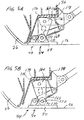
- the support shoe assembly 48 (see Figures 5A and 5B) comprises a pair of support shoe mechanisms 54, each having a support shoe 55 which provide firm support against the invert 56 of the tunnel 38 (the invert 56 being the bottom wall portion of the tunnel). The manner in which these provide constant vertical positioning of the cutterhead 26 will be described more completely hereinafter in a later section of this text.
- the gripper shoe assembly 50 provides the reaction for cutterhead thrust and torque, and also provides ground support until the primary supports are installed behind the gripper shoes.
- the gripper shoe assembly 50 (see Figures 6A - 6D) comprises eight gripper shoe mechanisms 58, these being arranged four on each side of the machine 10, with the gripper shoe mechanisms 58 being positioned at circumferentially spaced locations on opposite sides of the machine 10. These gripper shoe mechanisms 58 serve several functions. First, they support and position the forward part of the machine 10 in the tunnel 38. Second, they provide ground support for the tunnel surface on opposite sides of the machine. Third, these shoe mechanisms 58 are operated to advance the machine 10 into the tunnel as the boring operation progresses. In addition, the gripper shoes also have a steering function and other functions.
- the beam assembly 22 comprises a main beam 60, the front end 62 of which connects to (and is supported by) a central upper part of the circular support section 36 by means of a universal bearing joint which in the preferred form is a single spherical bearing 64.
- This beam 60 extends parallel to the longitudinal axis 16 to the rear end 14 of the machine 10.
- a gantry 66 To support the rear part of the main beam 60, as part of the beam assembly 22, there is provided a gantry 66 through which the beam 60 extends, this gantry 66 being supported by a wheeled trolley 68 that rides upon rails 70 that are laid along the invert 56 of the tunnel as the boring of the tunnel 38 proceeds.
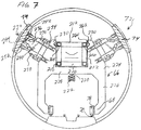
- This gantry 66 (see Figures 7, 8A and 8B) has a bearing and locating means 72 which comprises two bearing pads 74 positioned at upper locations on opposite sides of the gantry 66, just above the spring line 76 (this spring line being the transverse central line of the tunnel 38).
- the two bearing pads 74 cooperate with the wheels 78 of the trolley 70 to stabilize and position the gantry 66, so as to maintain the gantry at a fixed position in certain operating modes.
- the gantry 66 provides support for the beam 60, and among its other functions are the following. First, in certain situations, it reacts certain loads transmitted from the forward part of the machine 10 into the beam 60, into the gantry 66 and into the tunnel side wall. Second, it cooperates with other components to serve an alignment and alignment correction function. Third, in certain situations the gantry 66 fixedly positions the machine in the tunnel during at least one mode of operation of the gripper/propel /tunnel support assembly 20.
- the positioning and roll control mechanism 24 comprises four positioning cylinders 80 (see Figures 9, 10A, 10B and 11) and two roll cylinders 82 (see Figure 12), these cylinders 80 and 82 being interconnected between the forward part of the beam 60 and the head section structure 36. These cylinders 80 provide a redundant load path from the head section 18, and function in the steering of the cutterhead 26, and also positioning the cutterhead 26 relative to "roll". The manner in which these are accomplished will be described later herein.
- Each gripper shoe mechanism 58 has a related shoe 86, and these shoes 86 are positioned radially outwardly to engage the opposite side walls of the tunnel 38. Propel mechanisms (to be described later herein) of these gripper shoe mechanisms 58 pull the rear support section 36 of the head section 18 forwardly through an increment of forward travel, and thus pull substantially the entire machine 10 forwardly to enable the cutterhead to accomplish its boring operation.
- the gripper shoes 86 move the machine 10 forwardly in the tunnel 38 in relatively short increments of travel, and then the gripper shoes 86 are moved forwardly to continue the forward movement of the machine 10. This can be accomplished in several different operating modes, which will be described in a later section of this text.
- the roof shield mechanism 46 primarily serves as a support and shield function against the crown 52 of the tunnel.
- the roof shield 53 itself will remain in contact with the tunnel crown 52, and the pressure exerted by the roof shield 53 against the crown 52 will vary, depending upon the condition of the earth strata through which the tunnel 38 is being bored.
- the bottom support shoes 54 of the support shoe mechanism 48 support the front end of the machine 10 from the tunnel invert 56. These shoes 54 remain stationary on the tunnel invert 56 during each forward increment of travel of the machine 10, and then are moved forwardly to a more forward position adjacent to the lower perimeter edge 30 of the cutterhead 26 for the next increment of travel.
- the main beam 60 being connected to the head support structure 36, travels forwardly in the tunnel as the cutterhead 10 advances in its boring operation.
- the gantry 66 performs various positioning, load reacting and alignment functions.
- the gantry 66 generally remains stationary in the tunnel and is periodically moved forward in the tunnel in relatively large increments of travel as the machine 10 advances.
- the gantry 66 is generally positioned at approximately the mid-location or a mid-rear location along the beam 60.
- support structure for the tunnel wall is installed in the tunnel 38 immediately behind the gripper/propel/tunnel support assembly 20.
- the machine 10 of the present invention is arranged so that the overall method of the present invention is particularly suited where ring steel and shotcrete are used for primary ground support.
- the tunnel supports are installed behind the gripping mechanism 50, and for a very large machine (e.g. 30 feet in diameter) the tunnel supports could be approximately 2.8 meters behind the gauge cutter of the cutterhead 26. Since the supports are installed behind the gripper shoes 86, the supports are not disturbed by the high radial gripping forces necessary to react the cutterhead thrust and torque.
- the gripping mechanisms 58 and the roof member 53 can easily support the ground until the supports are installed.
- Providing the support can desirably accomplished by first positioning expandable support rings 88 in the tunnel as the machine 10 advances, and then adding additional structural material such as shotcrete.
- the tunnel support structure and the method of installing the same are, or may be, conventional, so this will not be discussed in detail herein.
- the head section 18 comprises a cutterhead 26, and also the support structure 32 comprising the front support section 34 and the rear support section 36.
- the cutterhead 26 can be mounted to the front support section 34 in a conventional manner, and the details of this are shown in Figure 2.
- the cutterhead 26 has a mounting structure portion 90 by which it is rotatably mounted to the forward ring support structure 34.
- the mounting structure 90 has a radially inward cylindrical plate section 92, and a radially outward surrounding section 94 with an interconnection portion being shown at 96.
- the cutterhead support structure 90 has a ring gear 102, with the teeth of this ring gear 102 facing radially inwardly.
- This ring gear 102 is engaged by a plurality of drive pinion gears 104, each operably connected to a related drive member 106 that is in turn connected to a related electric motor 108.
- Seal members and bolt connections are made at various locations indicated in Figure 2, but since these are (or may be) conventional, these will not be described herein.
- the support structure 32 comprises the forward cutterhead ring support section 34 and the more heavily constructed rear support section 36.
- the loads resulting from the engagement of the cutterhead 26 with the tunnel surface 40 are reacted from the cutterhead 26, through the bearing assemblies 98 into the front structure 34 and thence into the rear structure 36.
- the torque loads due to the resistance to rotation of the cutterhead 26 by its engagement with the tunnel surface 40 are imparted through the ring gear 102, through the pinion gears 104 into the rear structure 36.
- This ring-like structure 36 functions as the main structural component to react the loads into other operating components in the machine 10, as will be described more fully hereinafter.
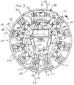
- This ring-like configuration of the rear support structure 36 can be seen in Figure 3. Further, it can be seen in Figure 1A that the cross section at each part of the ring of the structure 36 has a box-like configuration, with radially inward and outward positioned wall sections 114 and 116 respectively, and front and rear wall sections 118 and 120, respectively. Also, this structure 36 defines a central opening 122 for access, and to accommodate the conveyor 44. As can be seen in Figure 2, the radially outward wall 116 of the support structure 36 further comprises twelve plate sections 124 in a symmetrical, circumferential pattern of a twelve sided polygon. The upper two plate sections 124 provide support for the roof shield mechanism 46, and the bottom two plate sections 124 provide support for the lower shoe mechanism 48, while the remaining eight plate sections 124, four each on opposite sides of the machine 10, provide support for the eight gripper shoe mechanisms 58.
- Gripper and support assembly 20 (hereinafter called the "gripper and support assembly")
- cylinder is used (as is common in the tunnel boring art) in a broader sense to refer (unless specified otherwise) not simply to the cylindrical portion of a cylinder and piston assembly, but to the entire cylinder and piston assembly.
- This shield member 53 is an arcuate plate-like member following an arcuate curve coinciding with the circumference of the perimeter of the machine 10. This is shown as having an arcuate length of seventy degrees, but this could be made longer or shorter, depending on a number of factors.
- This shield member 53 has in cross section a reinforced box-like construction to withstand the potentially heavy loads which could be encountered from the crown 52 of the tunnel.
- the forward edge 134 of the shield member 53 is positioned a short distance rearwardly of the perimeter 30 of the cutterhead 26, and the rear part of the shield member 53 has a rearwardly extending tail portion 136 which is simply a rearward extension of the upper arcuate plate 138 of the shield member 53.
- the support rings 88 are initially placed within this tail portion 136. After the machine 10 has moved further forward, so that the support ring 88 is no longer within the tail portion 136, the support ring 88 is expanded against the tunnel wall to perform a support function. After that, further reinforcing structure can be positioned between adjacent support rings 88, and then shotcrete or other structural support material for the tunnel wall can be applied.
- the shield member 53 is supported by a parallel linkage 140 which enables the shield member 53 to be moved radially outwardly or inwardly, while maintaining substantial parallel alignment with the longitudinal center axis 16.
- this linkage 114 comprises two separate forward links 142 and a rear link 144 comprising a pair of laterally spaced arms 146 joined together by a cross member 148 (See Figure 3).
- the links 142 and arms 146 are mounted from related brackets or ears 149 mounted to the support structure 36 at pivot locations 150, and there are also upper brackets 152 at which there are pivot connections 154 for the upper ends of the links 142 and 144.
- a pair of cylinders 156 each connected at a lower rear pivot connection 158 to the rear radially outward part of the support structure 36, and connected at the forward end at a pivot connection 160 at the lower forward edge portion of the shield member 53.
- the two positioning cylinders 156 extend from the pivot locations 158 radially outwardly and forwardly at an angle of about 45° to the longitudinal axis 16.
- the links 142 and 146 extend radially outwardly and rearwardly at an angle of about 60° to the longitudinal axis 16.
- the shield member 132 will always maintain contact against the tunnel crown 52.
- the rock strata through which the tunnel 38 is being bored will contract or "creep" at a slow rate radially inwardly, usually with a higher rate of flow being expected at the location of the crown 52 and a slower rate of flow along the side wall portions 162 in the tunnel. (However, this could vary, depending on conditions.)
- the pressure in the cylinders 156 is set at a predetermined level to cause the shield 138 to exert the desired pressure against the tunnel crown 52.
- the upper surface of the shield member 132 will slide or "scuff" along the tunnel crown 52, still applying an upward pressure against the tunnel crown 52.
- the support shoe assembly 48 comprises the two support shoe mechanisms 54 spaced laterally from one another at the lower forward end of the machine 10, with each of these having a support shoe 55.
- Each shoe 55 has an arcuate curve matching that of the tunnel invert 56.
- Each mechanism 54 further comprises two roll links 166, and a positioning cylinder 168.
- Each shoe 55 has two pairs of upstanding connecting ears 170, to which the lower ends of its related two roll link 166 are connected at 172.
- the two links 166 are rigidly interconnected by a cross member 173.
- the upper end of each roll link 166 has a circularly curved upper bearing surface 174, with the curve of the bearing surface 174 having a radius of curvature with the pivot location 172 as its center.
- the upper bearing surfaces 174 of the two links 166 press against a downwardly facing bearing surface 176 of a structural member 178 connected to the support structure 36.
- the two shoes 55 are positioned at a more forward position, as shown in Figure 5A.
- the two shoes 55 remain at a fixed position relative to the tunnel invert 56, and as the machine moves forwardly, the two bearing surfaces 174 and 176 remain in rolling contact, with the two roller links 166 rotating forwardly about the pivot connection 172.
- Figure 5B the machine 10 has completed that particular segment of forward travel, and the two bearing surfaces 174 and 176 remain in contact.
- this gripper shoe assembly 50 comprises a total of eight gripper shoe mechanisms 58 positioned on opposite sides of the machine 10, as shown in Figure 3.
- Each gripper shoe mechanism 58 comprises the gripper shoe 86, and a gripper and propel actuating mechanism 179 which comprises a pair of cylinder links 180 and a propel cylinder 182.
- Each cylinder link 180 is pivotally connected at its radially inward end at a pivot location 184 where each cylinder link 180 is mounted to a related pair of ears 186 adjacent to the outer surface of the support structure 36.
- the radially outward end of the cylinder link 180 connects at an outer pivot location 188 to a pair of ears 190 connected at a forward to rear center location to the inner surface of the related shoe 86.
- a mounting bracket 192 which is connected to the radially outward surface of the mounting structure 36, and provides a connecting pivot location at 194 which is radially outward of, and just a short distance rearwardly of, the outer rear edge of the support structure 36.
- the propel cylinder 182 extends from this pivot location 194 forwardly at a moderate radially outward slant to connect at a forward pivot location 196 to a pair of ears 198 connected to the forward inside center portion of the related shoe 86.
- One main function of the gripper shoe assembly 50 is, as described previously, to grip the side wall of the tunnel on opposite sides of the machine 10 and provide a stationary reaction member to react the force of the propel cylinder 182 to advance the machine 10 one increment of travel. Also, the gripper shoe assembly 50 provides radial support for the adjacent tunnel wall. Further, as indicated previously herein, there are several modes of operation for the gripper shoe mechanisms 58, and these will be described later herein.
- the gripper shoe 86 is at its most forward position, and the propel cylinder 182 is in an extended position. It can be seen that the cylinder links 180 extend radially outwardly, but at a moderate forward slant of less than about 10° relative to a radius line drawn perpendicular to the longitudinal axis 16. As the propel cylinder 182 retracts, it moves the machine 10 forward relative to the shoe 86.
- the two links 180 rotate rearwardly about the pivot location 184, until at the completion of the increment of travel the two links 180 extend radially outwardly but at a rearward slant at a little less a 10° from a radius line drawn perpendicular to the longitudinal axis 16.
- the pressure in the cylinder links 180 is set at a predetermined pressure level in the gripping mode, and the length of the links 180 can change slightly as the cylinder links 180 rotate.
- the propel cylinders 182 are grouped in quadrants, with four pumps delivering an equal volume of oil to each quadrant. With this arrangement, the pressure in each quadrants automatically adjusts to react eccentric loads on the cutter head. The manner in which the flow to the propel cylinder is utilized for direction and advance control are discussed later in this text.
- FIG. 6C there is shown the shoe 86 and the four locations at which the forces from the propel cylinder 182 and the cylinder link 180 are transmitted, these being the pivot locations 184, 188, 194, and 196.
- Figure 6C corresponds to the position of the shoe 86 in Figure 6A, when the stroke of the propel cylinder 182 is just beginning. This is a tension force, as indicated by the arrows pointing toward each other at the line 182, representing the propel cylinder 182.
- the force exerted by the cylinder links 180 is a compression force pushing from the pivot locations 184 against the pivot points 188 which is at approximately the longitudinal center of the shoe 86.
- the force exerted by the propel cylinder 182 at the point 194 can be divided into two force components, namely a horizontal force component 194h and vertical force component 194v. Those forces are reacted into the bracket 192 which are in turn reacted into the support structure 36.
- the force exerted by the propel cylinder 182 at the pivot location 196 can be divided into the horizontal force component 196h and the vertical force component 196v.
- the horizontal component 196h is exerted into the shoe 86, and this is in turn reacted into the tunnel wall surface as a longitudinal force parallel force parallel to the tunnel wall, this being a forward horizontal force component indicated by the arrow 200.
- the compressive force at 180 that is reacted at 184 into the support structure 36 as a vertical force component 184v and a horizontal force component 184h.
- the force from the cylinder link 180 has a vertical force component 188v urging the shoe 86 against the tunnel wall, and a horizontal force component 188h which urges the shoe 86 in a forward direction.
- the vertical force component 188v is opposed by the vertical force component 196v, but here the alignment of the cylinder links 180 are such that the force component 188v is much larger.
- the force component 188v must be sufficient, relative to the coefficient friction of the tunnel wall against the shoe 86, so that the shoe 86 is able to grip the tunnel wall without sliding.
- Figure 6D corresponds to position shown in Figure 6B. It can be seen that the net vertical force 188v pushing the shoe 86 has changed little. Also, although the propel cylinder 182 has decreased in length, the alignment has changed only slightly. However, the horizontal force component 184h, which is relatively small, is now directed in a rearward direction. This is now additive to the horizontal force exerted at 194h, and in this instance, is thus adding to the force which moves the machine 10 in a forward direction.
- the horizontal force component 184h is relatively minor compared to the force component exerted at 194h.
- the net force which must be generated by the propel cylinder 182 would be somewhat greater.
- the horizontal force component 184h diminishes to zero.
- the horizontal force component 184h is reversed so that it is actually helping the propel cylinder 182 pull the machine 10 forward.
- the shoes 86 could be advanced by having one set of diametrically opposed shoes 86 gripping the side of the tunnel with a substantially higher force, while the shoes which are to be moved forwardly would have force exerted by their respective cylinder links 180 diminished (to diminish the force of friction against the tunnel wall) so that these shoes 86 can be moved forwardly, while still having something of a support function against the tunnel side wall surface.
- the beam assembly 22 comprises the main beam 60 and the gantry 66, with the forward end 62 of the beam 60 connected through a universal bearing 64 to the front main support structure 36, and the rear portion of the beam being supported from the gantry 66.
- a universal bearing 64 to the front main support structure 36
- the rear portion of the beam being supported from the gantry 66.
- the main beam structure has in cross section a rectangular configuration, comprising four longitudinal beams 210, interconnected in a rectangular configuration by cross beams 212, with these being reinforced by various diagonal braces 214.
- This main beam 60 performs a variety of functions. It supports the aforementioned conveyor 44 which extends through the beam and terminates at 216 a short distance behind the rear end 218 of the beam 60. Also, the beam 60 supports the operator's station, the transformer, electric cabinets 219, the hydraulic components and other subsystems. Suspended below the beam 60 and extending longitudinally is a monorail 220, to which is mounted a monorail hoist 222. Then there are the load bearing and other functions provided by the beam 60 in the overall operation of the present invention.
- the gantry 66 comprises an "H" shaped housing 224 comprising a pair of laterally spaced downwardly extending legs 226, joined at their upper ends by a cross member 228, and there are two laterally spaced upstanding upper leg portions 230 positioned on opposite sides of the main beam 60.
- the wheels 78 are mounted to the lower ends of the legs 226, and the aforementioned bearing and locating means 72 with the bearing pads 74, is mounted to the two upper leg portions 230.
- each bearing pad mechanism 232 there are two bearing pad mechanisms 232, each having one of the bearing pads 74 which are each supported from a related base plate 234 that is mounted to its related upper leg portion 230.
- Each bearing pad 74 is connected to its related base plate 234 through a single rigid link 236 and two positioning cylinders 238.
- the single rigid link 236 has a triangularly shaped main body portion 240, with the apex part of the triangular body portion ending as a radially outward mounting stub 242 having a central through opening by which it is joined to a pair of ears 244 between which is positioned a connecting pin (not shown for ease of illustration).
- the radially inward end of the link 236 has two laterally spaced mounting extensions 246, each of which is pivotally connected through a pair of ears 248 and a related pin to the base plate 234. It can be seen that the radially inward mounting location at 248 is radially inward and forwardly of the location of the related bearing pad 74.
- Each of the two mounting cylinders 238 is connected at its inner radially inward end to a pair of ears 250 connected to the plate 234, with the outer rod end of each cylinder 238 having a similar pivot connection at 252 to the pad 74.
- the two positioning cylinders 238 for each bearing pad mechanism 72 are aligned to be substantially perpendicular to the longitudinal axis 16. Thus, the outward force exerted by each cylinder 238 is perpendicular to the tunnel side wall.
- Each link 236 with the two cylinders 238 are thus able to position the related bearing pad 74 at a fixed location relative to the gantry housing 224.
- Each cylinder Extending forwardly from the gantry housing 224 are two gantry positioning cylinders 254, positioned on opposite sides of the main beam 60. Each cylinder has a rear connecting pivot location at 256 to the gantry housing 224, and a forward pivot connection at 258 to the main beam 60.
- a slideway member 260 which in cross sectional configuration has a trapezoidal shape, with its two converging side surfaces 262 extending toward one another in a laterally outward direction (See Figure 7).
- the two upper side housing sections 230 each have a matching elongate groove 264, having a cross section matching the related slideway member 260, to receive the related slideway member 260 in a close fitting slide relationship.
- Each slideway member 260 extends along the beam 60 a sufficient distance to maintain engagement with the gantry housing 224 throughout the entire length of travel of the gantry 66 relative to the beam 60.
- the two gripper shoes 74 In the usual mode of operation when the machine 10 is advancing in the tunnel as the head 26 is boring through the ground strata, the two gripper shoes 74 would be in engagement with the tunnel side wall to stabilize the position of the beam 30. During this time, the two positioning cylinders 254 would be in a float condition so that the beam 30 is free to advance as the boring operation continues. When the machine has advanced a certain length (e.g. three meters or so), then the pad mechanisms 232 would be retracted, and the cylinders 254 retracted to advance the gantry 66 to a more forward location.
- a certain length e.g. three meters or so
- the cylinders 254 would be used to cause the forward or rearward movement of the machine 10 in the tunnel, in which case the pads 74 would be pressed outwardly with sufficient force to be able to react the loads imposed thereon into the tunnel wall.
- the slide interconnection between the main beam 60 and the gantry housing 224, along with the action (or locking) of the positioning cylinders 154, as needed causes the vertical, lateral, longitudinal and torsional loads to be transmitted from the beam 60 into the gantry housing 224. With the two bearing pads 74 pressing against the tunnel wall, and with the wheels 78 in engagement with the rail 70, such vertical, lateral, longitudinal and torsional loads are in turn transmitted into the tunnel wall.
- Figure 9 is a simplified drawing, leaving out many components, and which is taken at location of 9-9 of Figure 1A. It can be seen by comparing Figure 9 with Figure 3 that most of the components located in the machine forwardly of the section line 3-3 have been omitted in Figure 9, and only the rear support section 36 and the mounting fittings 192 for the propel cylinders 182 and the cylinders 168 are shown.
- the four positioning cylinders 80 will have additional designations relative to their positions, as shown in Figure 9.
- cylinder 80-UR which is at an upper right location
- cylinder 80-LR at a lower right location
- cylinder 80-LL at a lower left location
- cylinder 80-UL at an upper left position.
- Each of these cylinders 80 have a rear pivot connecting end at 270 which connects to a related pair of ears 272 at the front lower end of the related lower longitudinal beam 210.
- each cylinder 80 has a pivot connection to a related one of the mounting members 192 which are fixedly connected to the rear structure section 36.
- the two lower cylinders 80-LR and 80-LL connect to the two lowermost connecting members 192 that are at the lowermost portion of the structure 36.
- the two cylinders 80-UR and 80-UL connect to the two connecting members 192 that are immediately below the spring line 76 (i.e. the lateral center line of the machine 10 and also of the tunnel).
- each of the cylinders 80 is designated at 274, and the ears connected to the related mounting member 192 to which the connection 274 are made are indicated at 276.
- the forward bearing connection 64 of the beam 60 to the structure section 36 is at a location above the two forward connections 274 of the two upwardly positioned cylinders 80-UR and 80-UL.
- the location of the center of the bearing 64 is indicated by an "X" at 278 in Figure 9.
- the forward part of the main beam 60 makes a connection with the rear support structure 36 at five different locations, with four of these locations being at the front ends of the four cylinders 80, and the fifth connection being at the universal bearing location 64.
- FIG 11 is a somewhat simplified side elevational view showing the lower left cylinder 80-LL.
- the cylinder 80-LL is being retracted, and let us assume that the lower right hand cylinder 80-LR is being retracted by the same amount as the left lower cylinder 80-LL.
- the cutting head 26 will be rotated about a transverse horizontal axis to face in a downward direction.
- these upper cylinders 80-UR and 80-UL will also have to be retracted a certain amount to properly accomplish the relative rotation of the head 26. Extending these cylinders will direct the cutterhead more upwardly.
- the four positioning cylinders 80 can be extended and retracted in various combinations to rotate the cutterhead 26 about the bearing location 64 so that there is a combination of changing lateral orientation of the cutting head 26 facing more toward one side or the other, along with a change in vertical direction of orientation either upwardly or downwardly.
- the positioning cylinders 80 itself could be used to change the position of the head section 18 by extending and retracting the cylinders in an appropriate pattern. However, as will be described later, it is contemplated that the alignment corrections would usually be made by modifying the flow rate of the hydraulic fluid to the propel cylinders 182. Thus, if the machine has gone off alignment toward the left, then the correction would be made by pumping more hydraulic fluid to the upper and lower left quadrants of propel cylinders 186 to extend these at a more rapid rate than the right quadrants of the propel cylinders 182.
- the misalignment is a result of the machine being orientated in a more upward or downward direction, then there would be the appropriate flow to the upper and lower quadrants of propel cylinders 186 to correct this misalignment. It is evident that by controlling the flow to the propel cylinders 186 in a selected pattern, the alignment change could be made in substantially any direction which would have both horizontal and vertical alignment components.
- the cylinders 82 would normally be utilized to correct the roll position as the machine 10 while the gripper shoes 36 are advancing in the tunnel 38.
- the gantry 66 would have its pads 74 pressing against the tunnel wall and as the gripper shoes 86 are being advanced, the roll cylinders 82 would be operated to exert a rotational force on the support structure 36.
- Figure 12 where the vertical orientation of the head section 18 is being moved from 284 to 282. It is important that the roll orientation of the head section 18 be maintained within rather precise limits, since the alignment control mechanisms of the machine 10 depend upon the proper roll orientation.
- the gripper shoes 86 are pressed outwardly against the tunnel side wall with a sufficient force to maintain their stationary positions against the tunnel wall, as they react into the tunnel wall the thrust loads and torsional loads imparted to the cutterhead 26 through the support structure 32 (and specifically into the rear support section 36, and thence into the shoes 86.
- the lower support shoes 55 engage the tunnel invert 56 to precisely locate the front part of the machine 10 at the proper elevation relative to the invert 56.
- the roof shield 53 presses against the tunnel crown 52 to resist downward movement of the crown of the tunnel immediately rearwardly of the perimeter 30 of the cutterhead 36.
- the electric motors 108 are operated to act through tee pinion gears 104 and the ring gear 102 to cause the cutterhead 26 to rotate.
- the propel cylinders 182 of all of the shoe mechanisms 58 (or some of the propel cylinders 182 for at least one mode of operation) are retracted to cause the machine 10 to advance. (The various modes of operation of the gripper shoe mechanism 58 will be described in the following sub-section.)
- rock fragments that are dislodged from the tunnel surface 40 are picked up by the scoop mechanism of the cutterhead 26 to be deposited into the hopper 42 to be deposited on a conveyor 44 to be carried to the rear end 14 of the machine and be carried away in a suitable manner.
- the four positioning cylinders 80 and also the roll cylinders 82 are locked in place. Also, the two support pads 74 of the gantry 66 (see Figure 7) are pushed outwardly against the tunnel side wall to stabilize the gantry 66 and the main beam 60 relative to the tunnel wall and also to enable the main beam 60 and the gantry 66 to react certain forces into the tunnel wall.
- the lower support shoes 55 remain stationary, relative to the tunnel invert 56.
- the circularly curved bearing surface 174 of each support link 166 being in engagement with the downwardly facing bearing surface 176 of the structure 136, maintains the support structure 36 to be positioned at a precisely controlled elevation above the tunnel invert 56.
- the positioning cylinders 156 are pressurized to a level to maintain the force exerted by the roof member 53 against the tunnel crown 52 at the desired level. Due to the action of the parallogram strut support assembly 140, the roof member 53 remains substantially parallel to the longitudinal axis 16.
- the upward force exerted by the roof shield member 53 could be rather substantial. With the machine 10 moving forwardly in the tunnel as the boring operation continues, the upper surface of the roof shield member 53 slides against the tunnel crown 52.
- the support rings 88 are moved into position within the tail portion 136 of the roof shield member 53 and also closely behind the gripper shoes 86 and the support shoes 55. After the machine 10 has moved a sufficient distance forward, then the most forward support ring 86 is expanded to be in supporting contact with the tunnel side wall, and further reinforcing structure is put into place, as described previously herein.
- the gripper shoe mechanisms 58 can advance the machine 10. In two of these operating modes, the advance of the machine is interrupted while the gripper shoes 86 are advanced. In the third mode, the advance of the machine is continuous.
- the operating mode which is selected will depend upon various factors, such as the character of the ground strata through which the tunnel is being bored.
- the first operating mode is accomplished as follows. With reference to Figure 6A, let us begin with all of the shoes being positioned at the forward location, as illustrated in 6A, and the support shoes 55 also in their forward position.
- the gripper cylinders 180 are pressing the shoes 86 outwardly against the tunnel wall. If the machine 10 is operating at a substantial depth beneath the ground surface, then the bearing pressure against the side wall would quite possibly be greater than the pressure which would be required simply to be able to react the loads from the cutterhead 26 into the tunnel side wall.
- the advance of the machine is accomplished by retracting all of the propel cylinders 182 simultaneously so that the gripper shoes 86 remain stationary against the tunnel wall, and the machine 10 is moved forwardly. During this time, the bottom support shoes 55 also remain stationary with the tunnel wall. Again, on the assumption that the machine 10 is operating at a substantial depth, the upward force exerted by the roof shield 53 may be substantial, and these vertical loads would be reacted through the shoes 55 into the surface of the tunnel invert 56. Also, as described previously, the roof shield 53 moves with the machine 10 as the roof shield 53 slides against the tunnel crown 52.
- the stroke of the propel cylinders 182 will depend upon the requirements for providing lateral support against the side walls of the tunnel converging immediately after the cutterhead forms that section of the tunnel wall. It is presently contemplated that for a large machine 10 having a cutter diameter as great as thirty feet, the maximum stroke of the gripper shoes 86 would be as great as one half a meter (0.5m).
- the two support shoes 55 would be advanced by extending the related cylinders 168.
- the support shoes 55 would desirably be advanced at a time when the vertical position of the forward part of the machine is fixed, such as having at least some (or all) of the gripper shoes 86 in firm engagement with the side wall of the tunnel.
- the gripper shoes 36 are also utilized to support the ground, the force required to cycle the shoes forward,is relatively high. As a result, only half of the shoes are advanced at a time, and the other half are in the grip mode providing the necessary reactive force.
- the assumed ground pressure on the shoes during advancement is 200 kN/m 2 .
- the advance cycle consists of:
- each boring advance takes 10.3 minutes.
- Each gripper shoe advance takes 0.5 minutes, and the 3m gantry advance takes 2.0 minutes.
- Time to advance 3m is 69.8 minutes or an advance rate of 2.58 meter per hour.
- the second mode of operation is similar to the first mode of operation, described immediately above, in that with the gripper shoes 86 in the forward position as shown in Figure 6A, all eight of the propel cylinders 182 are retracted to advance the machine 10 by a selected increment of travel. However, at the completion of the forward increment of travel, instead of advancing only two pair of oppositely positioned gripper shoes 86 (with the other four gripper shoes remaining in gripping contact with the tunnel wall at a stationary position), all eight of the gripper shoes 86 are advanced simultaneously.
- the gripper pads 74 of the gantry 66 would be pressed firmly against the tunnel side wall to react the thrust loads (and possibly other loads) which would be encountered by advancing all of the gripper shoes 86 simultaneously.
- the pressure in the gripper cylinders 180 would be reduced to a sufficiently low level. This second mode of operation would be used in the circumstances where there is no significant convergence of the tunnel side wall.
- the third mode of operation is, as indicated above, the continuous mode.
- two pairs of oppositely positioned gripper shoes 86 are always firmly gripping the side wall, while the machine is advancing forwardly, and at the same time the other two pairs of oppositely positioned shoes 86 are being moved forwardly to a position to firmly engage the tunnel side wall at such time as the propel cylinders 182 of the gripper shoes 86 engaging the side wall have completed their propel stroke.
- the set of two pair of gripper shoes 86 which have been moving forwardly are now pressed outwardly with a higher pressure, while at the same time the pressure against the tunnel side wall of the gripper shoes which have been in firm engagement is reduced, with these gripper shoes which have been in firm engagement now traveling forwardly.
- first set of shoes 86 (comprising two pair of oppositely positioned gripping shoes 86) is positioned forwardly as shown in Figure 6A, while the second set of shoes 86 are in a rearward position of Figure 6B.
- the pressure in the gripping cylinders 180 of the first set of shoes ( Figure 6A) is at a higher level so that the gripper shoes 86 in Figure 6A firmly engage the side wall of the tunnel.
- the second set of gripper shoes 86 in Figure 6B
- these have just completed their forward propel function, and their gripping cylinders 180 would now have their operating pressure reduced substantially.
- the propel cylinders of 182 of the first set of Figure 6A are now started to be retracted (with their related shoes 86 firmly gripping the tunnel side wall), while the propel cylinders 182 of the other set of shoes (shown in Figure 6B) are being extended.
- the shoes 86 of the second set of Figure 6B are traveling forwardly at twice the rate of forward travel of the machine 10.
- the second set of shoes 86 in Figure 6B have reached the forward position of Figure 6A, while the shoes 86 of the first set have reached the rear position of Figure 6B. Then the sequence is repeated.
- the changes and/or corrections relative to direction and roll will be made while the machine 10 is advancing in the tunnel.
- the positioning cylinders 80 and the roll control cylinders 82 would be in a locking mode so as to provide a redundant load path from the head section 16 into the beam 60 and gantry 66.
- the directional control could be accomplished by extending and retracting the cylinders 80 in a predetermined manner to obtain the desired change in direction. This could be accomplished, for example, while the machine 10 is stationary in the tunnel, and the gripper shoes 86 exerting possibly a lower pressure against the tunnel side wall.
- the beam 60 would be reacting the torque loads (and possibly other loads) through the gantry 66 into the tunnel side wall, with the positioning pads 74 of the gantry 66 being pressed against the tunnel side wall. Therefore, the positioning cylinders 254 for the gantry 66 would be in a lock position, or conceivably could be extended forwardly or rearwardly, as needed, depending upon precisely how the repositioning of the cutterhead 18 is being accomplished.
- roll control would normally be accomplished while the gripper shoes 86 are advancing in the tunnel.
- the positioning shoes or pads 74 of the gantry 66 would be pressing against the tunnel side wall.
- the roll control cylinders 82 are operated as shown in Figure 12, with one cylinder 82-L or 82-R being extended, and the other being retracted. This will exert a torque load into the support structure 36.
Landscapes
- Engineering & Computer Science (AREA)
- Mining & Mineral Resources (AREA)
- Environmental & Geological Engineering (AREA)
- Life Sciences & Earth Sciences (AREA)
- General Life Sciences & Earth Sciences (AREA)
- Geochemistry & Mineralogy (AREA)
- Geology (AREA)
- Excavating Of Shafts Or Tunnels (AREA)
Applications Claiming Priority (6)
| Application Number | Priority Date | Filing Date | Title |
|---|---|---|---|
| US1977196P | 1996-06-14 | 1996-06-14 | |
| US19771P | 1996-06-14 | ||
| US1672196P | 1996-06-21 | 1996-06-21 | |
| US16721P | 1996-06-21 | ||
| US763861 | 1996-12-11 | ||
| US08/763,861 US5890771A (en) | 1996-12-11 | 1996-12-11 | Tunnel boring machine and method |
Publications (1)
| Publication Number | Publication Date |
|---|---|
| EP0812979A1 true EP0812979A1 (fr) | 1997-12-17 |
Family
ID=27360640
Family Applications (1)
| Application Number | Title | Priority Date | Filing Date |
|---|---|---|---|
| EP97201789A Ceased EP0812979A1 (fr) | 1996-06-14 | 1997-06-13 | Machine de creusement de tunnels et procédé |
Country Status (1)
| Country | Link |
|---|---|
| EP (1) | EP0812979A1 (fr) |
Cited By (14)
| Publication number | Priority date | Publication date | Assignee | Title |
|---|---|---|---|---|
| CN102877851A (zh) * | 2012-08-31 | 2013-01-16 | 中铁隧道集团有限公司 | 一种敞开式硬岩掘进机在城市地铁施工中的弧底步进过站方法 |
| CN103758528A (zh) * | 2014-01-03 | 2014-04-30 | 大连理工大学 | 一种掘进机刀盘溜碴板曲面的设计方法 |
| CN107448206A (zh) * | 2017-07-14 | 2017-12-08 | 华东交通大学 | 一种带双三足支撑器和负载均衡器的混联式tbm支撑装置 |
| CN107989625A (zh) * | 2017-12-06 | 2018-05-04 | 秦汉新城永顺掘进设备开发工程有限责任公司 | 轴心驱动式1000mm以内微型盾构机 |
| WO2019025959A1 (fr) * | 2017-07-31 | 2019-02-07 | Drilling Technical Services (Pty) Ltd | Agencement de tunnelier souterrain mobile |
| CN109854265A (zh) * | 2019-02-26 | 2019-06-07 | 重庆交通建设(集团)有限责任公司 | 三臂凿岩台车稳定施工方法及稳定台架 |
| CN110424976A (zh) * | 2019-07-30 | 2019-11-08 | 中国地质大学(北京) | 多段曲面盾构刀盘 |
| CN111441776A (zh) * | 2020-01-03 | 2020-07-24 | 武汉市市政建设集团有限公司 | 一种用于空推过暗挖初衬隧道的机头结构及施工方法 |
| CN113338958A (zh) * | 2021-07-14 | 2021-09-03 | 成都未来智隧科技有限公司 | 掘进机护盾和掘进设备 |
| CN114637207A (zh) * | 2022-03-19 | 2022-06-17 | 四川大学 | 用于盾构隧道弧形件安装机的抗扰同步步态控制方法 |
| CN115749945A (zh) * | 2022-11-14 | 2023-03-07 | 中国铁建重工集团股份有限公司 | 一种隧道植筋装置 |
| CN116378686A (zh) * | 2023-05-06 | 2023-07-04 | 河南五建建设集团有限公司 | 盾构机用盾体撑紧装置和盾构机 |
| CN119900576A (zh) * | 2025-01-21 | 2025-04-29 | 中国铁建重工集团股份有限公司 | 一种履带式岩石隧道掘进机及其转场方法 |
| CN119900578A (zh) * | 2025-01-21 | 2025-04-29 | 中国铁建重工集团股份有限公司 | 一种可多方向撑紧洞壁的tbm主梁支撑推进装置 |
Citations (7)
| Publication number | Priority date | Publication date | Assignee | Title |
|---|---|---|---|---|
| US3061287A (en) * | 1959-04-17 | 1962-10-30 | Goodman Mfg Co | Feeding means for rotary head tunneling machine |
| DE1285494B (de) * | 1965-11-09 | 1968-12-19 | Masch U Bohrgeraetefabrik A W | Vortriebsmaschine zum Auffahren von Tunneln, Stollen od. dgl. |
| EP0115942A2 (fr) * | 1983-01-27 | 1984-08-15 | Harrison Western Corporation | Machine de percement de tunnel |
| US4548443A (en) * | 1984-07-03 | 1985-10-22 | The Robbins Company | Tunnel boring machine |
| WO1989010466A1 (fr) * | 1988-04-18 | 1989-11-02 | Fikse Tyman H | Machine a creuser des tunnels, a quatre patins de frottement |
| WO1992022730A1 (fr) * | 1991-06-17 | 1992-12-23 | The Robbins Company | Machine de forage de tunnel a propulsion continue vers l'avant |
| US5527099A (en) * | 1994-05-09 | 1996-06-18 | Fikse; Tyman H. | Tunnel boring machine anchor shoe structure and process of operating a tunnel boring machine having such anchor shoe structure |
-
1997
- 1997-06-13 EP EP97201789A patent/EP0812979A1/fr not_active Ceased
Patent Citations (7)
| Publication number | Priority date | Publication date | Assignee | Title |
|---|---|---|---|---|
| US3061287A (en) * | 1959-04-17 | 1962-10-30 | Goodman Mfg Co | Feeding means for rotary head tunneling machine |
| DE1285494B (de) * | 1965-11-09 | 1968-12-19 | Masch U Bohrgeraetefabrik A W | Vortriebsmaschine zum Auffahren von Tunneln, Stollen od. dgl. |
| EP0115942A2 (fr) * | 1983-01-27 | 1984-08-15 | Harrison Western Corporation | Machine de percement de tunnel |
| US4548443A (en) * | 1984-07-03 | 1985-10-22 | The Robbins Company | Tunnel boring machine |
| WO1989010466A1 (fr) * | 1988-04-18 | 1989-11-02 | Fikse Tyman H | Machine a creuser des tunnels, a quatre patins de frottement |
| WO1992022730A1 (fr) * | 1991-06-17 | 1992-12-23 | The Robbins Company | Machine de forage de tunnel a propulsion continue vers l'avant |
| US5527099A (en) * | 1994-05-09 | 1996-06-18 | Fikse; Tyman H. | Tunnel boring machine anchor shoe structure and process of operating a tunnel boring machine having such anchor shoe structure |
Cited By (23)
| Publication number | Priority date | Publication date | Assignee | Title |
|---|---|---|---|---|
| CN102877851B (zh) * | 2012-08-31 | 2015-01-07 | 中铁隧道集团有限公司 | 一种敞开式硬岩掘进机在城市地铁施工中的弧底步进过站方法 |
| CN102877851A (zh) * | 2012-08-31 | 2013-01-16 | 中铁隧道集团有限公司 | 一种敞开式硬岩掘进机在城市地铁施工中的弧底步进过站方法 |
| CN103758528A (zh) * | 2014-01-03 | 2014-04-30 | 大连理工大学 | 一种掘进机刀盘溜碴板曲面的设计方法 |
| CN103758528B (zh) * | 2014-01-03 | 2016-06-01 | 大连理工大学 | 一种掘进机刀盘溜碴板曲面的设计方法 |
| CN107448206A (zh) * | 2017-07-14 | 2017-12-08 | 华东交通大学 | 一种带双三足支撑器和负载均衡器的混联式tbm支撑装置 |
| CN107448206B (zh) * | 2017-07-14 | 2019-02-19 | 华东交通大学 | 一种带双三足支撑器和负载均衡器的混联式tbm支撑装置 |
| CN111684144A (zh) * | 2017-07-31 | 2020-09-18 | 钻井技术服务(私人)有限公司 | 移动式地下隧道掘进机装置 |
| WO2019025959A1 (fr) * | 2017-07-31 | 2019-02-07 | Drilling Technical Services (Pty) Ltd | Agencement de tunnelier souterrain mobile |
| CN111684144B (zh) * | 2017-07-31 | 2023-02-17 | 钻井技术服务(私人)有限公司 | 移动式地下隧道掘进机装置 |
| US11434762B2 (en) | 2017-07-31 | 2022-09-06 | Drilling Technical Services (Pty) Ltd | Mobile underground tunnel borer arrangement |
| CN107989625A (zh) * | 2017-12-06 | 2018-05-04 | 秦汉新城永顺掘进设备开发工程有限责任公司 | 轴心驱动式1000mm以内微型盾构机 |
| CN109854265A (zh) * | 2019-02-26 | 2019-06-07 | 重庆交通建设(集团)有限责任公司 | 三臂凿岩台车稳定施工方法及稳定台架 |
| CN110424976A (zh) * | 2019-07-30 | 2019-11-08 | 中国地质大学(北京) | 多段曲面盾构刀盘 |
| CN110424976B (zh) * | 2019-07-30 | 2024-04-16 | 中国地质大学(北京) | 多段曲面盾构刀盘 |
| CN111441776A (zh) * | 2020-01-03 | 2020-07-24 | 武汉市市政建设集团有限公司 | 一种用于空推过暗挖初衬隧道的机头结构及施工方法 |
| CN113338958A (zh) * | 2021-07-14 | 2021-09-03 | 成都未来智隧科技有限公司 | 掘进机护盾和掘进设备 |
| CN113338958B (zh) * | 2021-07-14 | 2023-12-05 | 成都未来智隧科技有限公司 | 掘进机护盾和掘进设备 |
| CN114637207A (zh) * | 2022-03-19 | 2022-06-17 | 四川大学 | 用于盾构隧道弧形件安装机的抗扰同步步态控制方法 |
| CN115749945A (zh) * | 2022-11-14 | 2023-03-07 | 中国铁建重工集团股份有限公司 | 一种隧道植筋装置 |
| CN115749945B (zh) * | 2022-11-14 | 2025-08-15 | 中国铁建重工集团股份有限公司 | 一种隧道植筋装置 |
| CN116378686A (zh) * | 2023-05-06 | 2023-07-04 | 河南五建建设集团有限公司 | 盾构机用盾体撑紧装置和盾构机 |
| CN119900576A (zh) * | 2025-01-21 | 2025-04-29 | 中国铁建重工集团股份有限公司 | 一种履带式岩石隧道掘进机及其转场方法 |
| CN119900578A (zh) * | 2025-01-21 | 2025-04-29 | 中国铁建重工集团股份有限公司 | 一种可多方向撑紧洞壁的tbm主梁支撑推进装置 |
Similar Documents
| Publication | Publication Date | Title |
|---|---|---|
| US5890771A (en) | Tunnel boring machine and method | |
| EP0812979A1 (fr) | Machine de creusement de tunnels et procédé | |
| US4494799A (en) | Tunnel boring machine | |
| AU659378B2 (en) | Mobile mining machine having tilted swing axis | |
| CN108286440B (zh) | 一种新型复合防卡单护盾tbm及其施工方法 | |
| AU767573B2 (en) | Mining machine and mining method | |
| US4420188A (en) | Double shield tunnel boring machine | |
| US6585062B2 (en) | Steerable directional drilling reamer | |
| US4494617A (en) | Shaft boring machine | |
| EP0414753B1 (fr) | Machine a creuser des tunnels, a quatre patins de frottement | |
| US4637657A (en) | Tunnel boring machine | |
| US12421802B2 (en) | Method and system for mining | |
| US3963080A (en) | Tunneling machine for boring a side drift | |
| CN217001866U (zh) | 柔臂掘进机 | |
| EP0223575A2 (fr) | Appareil de forage | |
| US5005911A (en) | Quadrishoe tunnel boring machine | |
| EP0115942A2 (fr) | Machine de percement de tunnel | |
| CN118601575A (zh) | 一种竖井扩孔掘进机组合式推进系统 | |
| AU2018254652B2 (en) | Cutting apparatus | |
| CN113756713B (zh) | 一种适用于矿山井下端面的综掘钻装一体机 | |
| US5527099A (en) | Tunnel boring machine anchor shoe structure and process of operating a tunnel boring machine having such anchor shoe structure | |
| CN115749807B (zh) | 非圆形隧道掘进装备及开挖方法 | |
| CN2540508Y (zh) | 矿用大直径平孔钻机 | |
| US4254993A (en) | Mining apparatus | |
| CN114382501A (zh) | 一种维持隧道掌子面稳定的开挖支护一体化施工方法 |
Legal Events
| Date | Code | Title | Description |
|---|---|---|---|
| PUAI | Public reference made under article 153(3) epc to a published international application that has entered the european phase |
Free format text: ORIGINAL CODE: 0009012 |
|
| AK | Designated contracting states |
Kind code of ref document: A1 Designated state(s): AT CH DE FR GB IT LI |
|
| 17P | Request for examination filed |
Effective date: 19980617 |
|
| AKX | Designation fees paid |
Free format text: AT CH DE FR GB IT LI |
|
| RBV | Designated contracting states (corrected) |
Designated state(s): AT CH DE FR GB IT LI |
|
| GRAG | Despatch of communication of intention to grant |
Free format text: ORIGINAL CODE: EPIDOS AGRA |
|
| 17Q | First examination report despatched |
Effective date: 20010606 |
|
| STAA | Information on the status of an ep patent application or granted ep patent |
Free format text: STATUS: THE APPLICATION HAS BEEN REFUSED |
|
| 18R | Application refused |
Effective date: 20020202 |