EP0812991A2 - Vérin à fluide sous pression - Google Patents
Vérin à fluide sous pression Download PDFInfo
- Publication number
- EP0812991A2 EP0812991A2 EP97100210A EP97100210A EP0812991A2 EP 0812991 A2 EP0812991 A2 EP 0812991A2 EP 97100210 A EP97100210 A EP 97100210A EP 97100210 A EP97100210 A EP 97100210A EP 0812991 A2 EP0812991 A2 EP 0812991A2
- Authority
- EP
- European Patent Office
- Prior art keywords
- cylinder
- working cylinder
- cover
- pressure medium
- longitudinal
- Prior art date
- Legal status (The legal status is an assumption and is not a legal conclusion. Google has not performed a legal analysis and makes no representation as to the accuracy of the status listed.)
- Granted
Links
Images

Classifications
-
- F—MECHANICAL ENGINEERING; LIGHTING; HEATING; WEAPONS; BLASTING
- F15—FLUID-PRESSURE ACTUATORS; HYDRAULICS OR PNEUMATICS IN GENERAL
- F15B—SYSTEMS ACTING BY MEANS OF FLUIDS IN GENERAL; FLUID-PRESSURE ACTUATORS, e.g. SERVOMOTORS; DETAILS OF FLUID-PRESSURE SYSTEMS, NOT OTHERWISE PROVIDED FOR
- F15B15/00—Fluid-actuated devices for displacing a member from one position to another; Gearing associated therewith
- F15B15/20—Other details, e.g. assembly with regulating devices
- F15B15/28—Means for indicating the position, e.g. end of stroke
- F15B15/2892—Means for indicating the position, e.g. end of stroke characterised by the attachment means
Definitions
- the invention relates to a pressure-operated cylinder according to the type specified in the preamble of claim 1.
- connection bores for supplying and discharging pressure medium lie in a cover and a base, which are flanged onto the end of the cylinder liner.
- connection bores are centered with respect to the axes of symmetry of the outer contour of the cylinder liner and also in a profile strip and each have an arcuate bulge projecting into the flange surface, which protrude into suitable recesses in the cylinder liner.
- the lid and base can be made flat and allow a short axial construction of the short-stroke cylinder.
- the disadvantage is that the connection side of the short-stroke cylinder having connection bores has no longitudinal groove for fastening a signal transmitter, since there is no longer any space for such a signal.
- the working cylinder must therefore be installed at its place of use in such a way that at least two outer sides are accessible for the pneumatic and electrical line connections at the connection bores and on an electrical signal transmitter, but this is not possible in many applications. It is also unfavorable that the four fastening screws for the lid and the bottom each lie on the corners of a square on which the four longitudinal bores for fastening the working cylinder to a machine part also lie.
- the fastening screws are designed in a complex manner as expensive hollow screws with an internal thread, which make it difficult to fasten the working cylinder with, for example, tie rods and require a larger construction in order to accommodate the standardized fastening thread in the hollow screws.
- An anti-rotation device for the piston of the working cylinder is not provided.
- a pneumatic compact cylinder in which a contactless piston position inquiry is provided with the help of a ring magnet integrated in the piston.
- the housing consists of a drawn profile tube, in the longitudinal bore receiving the piston, a cover and a bottom are inserted, while the connection bores lie in an axially extending connecting strip on the housing.
- the connection bores lie in an axially extending connecting strip on the housing.
- the pressure-actuated working cylinder according to the invention with the characterizing features of claim 1 has the advantage that it enables a series of compact working cylinders in which different variants can be assembled in a simple manner, the possible uses of which are more diverse. Due to the asymmetrical design of the connection side with regard to connection bores and longitudinal groove, the working cylinder is suitable for applications in which the pressure medium connections and the cylinder switch are only accessible from a single side. The design of the working cylinder can also be applied to a series of cylinders that are designed with different diameters and different strokes. The axially continuous longitudinal groove in the lid and base creates sufficient space for positioning a cylinder switch. In addition, the working cylinder is space-saving and inexpensive.
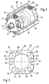
- FIG. 1 shows a first embodiment of the working cylinder according to the invention in a perspective view
- FIG. 2 shows a frontal side view of the cylinder liner of the working cylinder according to FIG. 1 on a slightly enlarged scale
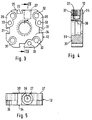
- FIG. 3 shows a front view of a cover of the working cylinder according to FIG. 1 on a slightly enlarged scale
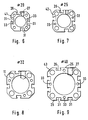
- Figure 5 is a plan view of the cover and Figures 6 to 9 in a simplified representation of the profiles for the cylinder liners for a series of working cylinders for different standard diameters.
- Figures 10 and 11 show the profiles for the cylinder liner of a fifth and sixth embodiment in a simplified representation.
- FIG. 1 shows, as a first exemplary embodiment, a working cylinder 10 which can be actuated by pressure medium and which, due to its small external dimensions, is also referred to as a compact cylinder, generally operates with a short stroke and is therefore used in confined spaces.
- a working cylinder 10 which can be actuated by pressure medium and which, due to its small external dimensions, is also referred to as a compact cylinder, generally operates with a short stroke and is therefore used in confined spaces.
- the working cylinder 10 consists essentially of a cylinder liner 11 made of drawn profile tube with a suitable cross section, which is closed at the end by a cover 12 and a base 13 and thereby forms an interior 14 in which an axially guided piston 15 is slidably mounted.
- the piston 15 is connected to a piston rod 16 which projects through the cover 12 to the outside.
- the cover 12 and the base 13 are each screwed to the cylinder liner 11 by three commercially available fixing screws 17, the fixing screws on the cover 12 and on the base 13 being coaxial to one another and arranged on the same diameter with respect to the longitudinal axis of the working cylinder 10 but they are distributed unevenly in the circumferential direction.
- FIG. 1 shows a side view of the cylinder liner 11 on the front side facing the cover 12 on a somewhat enlarged scale
- the working cylinder 10 essentially has a square outer contour, in which the corners are flattened.
- This outer contour is identical for the cylinder liner 11, the cover 12 and the bottom 13.
- the two axes of symmetry 18 and 19 are given for this outer contour, which are the cross-section of FIG Split cylinder liner 11 into four quadrants 21 to 24. It can be seen particularly clearly in FIG.
- connection side 25 of the working cylinder 10 extends in the first quadrant 21 and in the fourth quadrant 24, and in this connection side 25 in the fourth quadrant 24 a longitudinal groove 26 runs laterally offset from the axis of symmetry 18 and is used for fastening Signalers is used.
- this longitudinal groove 26 runs over the entire length of the working cylinder 10 and also penetrates the cover 12 and the bottom 13.
- first connection bore 27 in the connection side 25 in the area of the cover 12 and in the area of the bottom 13 a second connection bore 28 is formed.
- connection bores 27, 28 are connected to the chambers on both sides of the piston 15, so that each side of the piston 15 can be acted upon or relieved of compressed air.
- connection bore 27, like the connection bore 28, is laterally offset from the axis of symmetry 18 and also in the first quadrant 21, as can be seen particularly clearly from FIG. 1 in connection with FIG. 3, which shows a front view of the cover 12. Due to this asymmetrical arrangement of the connection bores 27, 28, a longitudinal groove 26 can also be arranged in the connection side 25, the connection side 25 itself being able to be designed as a flat surface.
- the three longitudinal sides 29 of the working cylinder 10 that remain next to the connection side 25 each have a longitudinal groove 31 which runs continuously in the same way as the longitudinal groove 26 and has the same cross section. In this way, all four sides of the working cylinder 10 are suitable for mounting a signal transmitter.
- the outer wall of the working cylinder 10 has in the region of the first quadrant 21 no longitudinal groove, while the longitudinal groove 31 in the second quadrant 22 borders directly on the axis of symmetry 19.
- the longitudinal grooves 31 of two longitudinal sides 29 are each arranged adjacent to the axes of symmetry 18 and 19.
- FIG. 2 and FIG. 3 show in more detail, four continuous mounting bores 32, which serve as mounting through holes, are provided on the corners of a square and are used in a manner not shown for fastening the working cylinder 10 to a machine element.
- the size, position and spacing of these mounting holes 32 are standardized in such compact cylinders and must therefore meet certain requirements depending on the size of the working cylinder.
- the continuous mounting holes 32 in the cylinder sleeve 11 therefore run coaxially in the cover 12 and in the bottom 13.
- the cylinder liner 11 can be produced in this way from an extruded tubular material, in particular a profile tube, the length of the cylinder liner 11 being selected when a rod-shaped material is cut to length so that a desired stroke is achieved. For the production of the working cylinder 10 are therefore on the profile tube existing cylinder liner 11 no additional operations required.
- FIG. 3 shows a front view of the cover 12 according to FIG. 1, while FIG. 4 shows a longitudinal section according to IV-IV in FIG. 3 and FIG. 5 shows a top view of the cover according to FIG. 3.
- clamping surfaces 35 are formed on the cover 12 from the outer end face 34, which are axially offset inwards and include at least the mounting holes 32 in each of the four quadrants 21 to 24 and additionally in the First, second and fourth quadrant enclose the longitudinal bores 33 for screw fastening and are additionally delimited by a longitudinal groove 31.
- the clamping surfaces 35 are so deep that the heads of the fastening screws 17 are arranged sunk relative to the end face 34.
- the mounting holes 32 can be provided with a thread in the area of the cover 12, with the aid of which the working cylinder 10 can be screwed tight during assembly.
- the connection bore 27 in the cover 12 is connected via a bore 36 to a chamber in the interior of the working cylinder 10, so that pressure medium can act on or relieve the pressure on the piston 15.
- the cover 12 has, on its flange surface 37 opposite the end surface 34, an annular collar 38 which projects slightly from the flange surface 37 and with which the cover 12 is centered in the interior 14 of the cylinder liner 11 which is circular in cross section.
- the collar 38 is surrounded by an annular groove 39 for receiving an O-ring, which ensures a secure seal when the cover 12 and cylinder liner 11 are assembled.
- the bottom 13 is designed in a manner corresponding to the cover 12, and accordingly has comparable clamping surfaces 35 and a corresponding bore for connecting the second connection bore 28 to the interior 14. Instead of a bushing passing through, the base 13 can be closed.
- a magnet not shown, is arranged in a manner known per se, with the aid of which the piston position in the working cylinder 10 is to be determined.
- the mode of operation of the working cylinder 10 is known per se, which can be operated as a single-acting or double-acting short-stroke cylinder.
- the working cylinder 10 has a continuous longitudinal groove 26, 31 on all of its longitudinal sides 29, including the connecting side 25, in which signal transmitters known per se can be fastened. These signal transmitters can be designed as magnetic field switches, as reed switches or in any other way.
- the longitudinal grooves 26, 31 are also formed continuously in the cover 12 and in the base 13 in order to create the necessary space for the positioning of the signal transmitter.
- connection side 25 The space for the longitudinal groove 26 in the connection side 25 is made possible above all by the eccentric connection bores 27, 28 and the special position of the fastening screws 7 outside the axes of symmetry of the outer contour of the profile tube and their position at a distance from the mounting holes 32.
- the connection side 25 of the working cylinder 10 thus offers space for the pressure medium connections to the working cylinder 10 and also space for fastening and connecting an electromagnetic cylinder switch. The full function of the working cylinder 10 can therefore be exploited if its accessibility is limited only to the connection side 25.
- FIGS. 6 to 9 show the application of the design according to the invention to a series of working cylinders with different diameters
- FIG. 8 corresponding to the first exemplary embodiment according to FIGS. 1 and 2 and representing the conditions on the cylinder liner 11 with a standard diameter of 32 mm.
- FIG. 6 shows the conditions on a cylinder liner 41 for a standard diameter of 20 mm
- FIG. 7 shows the cylinder liner 42 of a third exemplary embodiment for a standard diameter 25 mm
- FIG. 9 shows the cylinder liner 43 of a fourth exemplary embodiment for a Standard diameter 40 mm.
- the fourth cylinder liner 43 differs from the first cylinder liner 11 according to FIG. 8 primarily in that four continuous longitudinal bores 33 are now provided for the fastening screws 17, which lie directly on the axes of symmetry 18 and 19. While in the connecting side 25 of the working cylinder 10 the continuous longitudinal groove 26 and the connecting bores 27 and 28 are each eccentric and on opposite sides of the axis of symmetry 18, there are three on the remaining three Longitudinal sides 29 each have two longitudinal grooves 31 arranged symmetrically to the axes of symmetry 18 and 19, respectively.
- the through bores, grooves and clamping surfaces must be adapted in accordance with the design of the cylinder liners 41 to 43, as is shown and described in principle in the first exemplary embodiment 10.
- FIGS. 10 and 11 show, from a fifth or sixth exemplary embodiment of a working cylinder, the conditions at a fifth (45) or sixth cylinder liner 46, corresponding to FIGS. 7 and 9.
- the fifth and sixth cylinder liner 45, 46 enables compared to the third and fourth cylinder liner 42 and 43, above all, a lighter and less expensive design and increased symmetry.
- four mounting through holes 47 are no longer round, but are designed with a shape-adapted cross section. This shape-adjusted cross section extends between the now rounded corner of the outer contour, the interior 14, the longitudinal bore 33 and the longitudinal groove 26 and 31.
- the larger, shape-matched cross section compared to the round mounting hole serves to save weight and thus reduce costs.
- suitable positioning of anti-twist bars can prevent the drawn assembly through holes 47 from being bored out, so that no profile machining is required.
- the profile of the fifth cylinder liner 45 is preferably suitable for the standard diameters according to FIGS. 6 and 7.
- the longitudinal bore 33 is always present four times, ie one per quadrant 21-24, these longitudinal bores 33 being arranged rotationally symmetrically.
- the cover is fastened with two screws in two of these longitudinal bores 33.
- the longitudinal grooves 26, 31 are also arranged rotationally symmetrically, the longitudinal grooves 26, 31 having a center offset. In this way, all quadrants 21-24 are congruent with each other; the cover can therefore be installed rotated by 90 degrees.
- a longitudinal bore 33 which is not required can also serve as an air duct for supplying pressure to an opposite chamber.
- the sixth cylinder liner 46 is provided for a standard diameter as in FIG. 9.
- the longitudinal bores 33 no longer lie on the axes of symmetry and are arranged rotationally symmetrically.
- the longitudinal grooves 31 are arranged twice, which allows the arrangement of two cylinder switches on the same side for short strokes.
- the sixth cylinder sleeve 46 has the same symmetry as the fifth cylinder sleeve 45.
- Both cylinder liners 45, 46 according to FIGS. 10 and 11 have the advantage that they are particularly suitable for securing against rotation.
- the rounded corners and the form-fitting mounting through holes result in a sufficiently large cross section so that two circular guide bushes can be arranged in the cover, which can protrude into the mounting through holes 47 without touching them.
- the anti-rotation rods guided in the guide bushes shown in simplified form in FIG. 11 with 48, are externally connected to one another and to the piston rod 16 by a yoke and provide anti-rotation protection for the longitudinally movable piston 15.
- the position of these guide bushes in the cover can therefore be chosen more freely; the anti-rotation device for the piston 15 can be carried out on the cylinder bush 45, 46 without profile machining.
- the clamping surfaces 35 according to FIG. 3 can also be formed by annular depressions, so that the mounting bores 32 are essentially surrounded by a web of material.
- the longitudinal grooves 31 can also run at a distance from the clamping surfaces 35, so that a web of material remains between the two.
- an axial bore arrangement can also be selected.
- the design with mounting through holes can also be applied to a cylinder liner with the standard diameter according to FIG. 8.
Landscapes
- Engineering & Computer Science (AREA)
- Physics & Mathematics (AREA)
- Fluid Mechanics (AREA)
- Mechanical Engineering (AREA)
- General Engineering & Computer Science (AREA)
- Actuator (AREA)
Applications Claiming Priority (2)
| Application Number | Priority Date | Filing Date | Title |
|---|---|---|---|
| DE19623757 | 1996-06-14 | ||
| DE19623757A DE19623757A1 (de) | 1996-06-14 | 1996-06-14 | Druckmittelbetätigbarer Arbeitszylinder |
Publications (3)
| Publication Number | Publication Date |
|---|---|
| EP0812991A2 true EP0812991A2 (fr) | 1997-12-17 |
| EP0812991A3 EP0812991A3 (fr) | 1998-07-22 |
| EP0812991B1 EP0812991B1 (fr) | 2001-10-10 |
Family
ID=7796952
Family Applications (1)
| Application Number | Title | Priority Date | Filing Date |
|---|---|---|---|
| EP97100210A Expired - Lifetime EP0812991B1 (fr) | 1996-06-14 | 1997-01-09 | Vérin à fluide sous pression |
Country Status (2)
| Country | Link |
|---|---|
| EP (1) | EP0812991B1 (fr) |
| DE (2) | DE19623757A1 (fr) |
Families Citing this family (2)
| Publication number | Priority date | Publication date | Assignee | Title |
|---|---|---|---|---|
| DE10112637A1 (de) * | 2001-03-14 | 2002-09-19 | Continental Teves Ag & Co Ohg | Aus einem Strang abgeschnittenes Rohteil f. einen Hauptzylinder sowie hieraus gefertigter Hauptzylinder |
| DE102008036230B4 (de) * | 2008-08-02 | 2010-07-01 | Nordex Energy Gmbh | Verfahren zur Montage einer Rotornabe an einer Rotorwelle einer Windenergieanlage und Windenergieanlage |
Citations (2)
| Publication number | Priority date | Publication date | Assignee | Title |
|---|---|---|---|---|
| DE3507167A1 (de) | 1985-03-01 | 1986-09-04 | Festo KG, 7300 Esslingen | Kolben-zylinder-anordnung |
| EP0692635A2 (fr) | 1990-03-27 | 1996-01-17 | Leybold Aktiengesellschaft | Pompe à vide multiétagée avec compression à sec et son procédé de fonctionnement |
Family Cites Families (5)
| Publication number | Priority date | Publication date | Assignee | Title |
|---|---|---|---|---|
| FR2425567A1 (fr) * | 1978-05-12 | 1979-12-07 | Outillage Air Comprime | Verin |
| GB2230385B (en) * | 1989-04-08 | 1993-10-13 | Festo Kg | A control device |
| DE9309589U1 (de) * | 1993-06-29 | 1994-02-24 | A. Römheld GmbH & Co KG, 35321 Laubach | Blockzylinder mit Positionskontrolle |
| IT233859Y1 (it) * | 1994-07-13 | 2000-02-10 | Luciano Migliori | Cilindro pneumatico compatto |
| DE4438164A1 (de) * | 1994-10-26 | 1996-05-02 | Festo Kg | Antriebsvorrichtung |
-
1996
- 1996-06-14 DE DE19623757A patent/DE19623757A1/de not_active Withdrawn
-
1997
- 1997-01-09 EP EP97100210A patent/EP0812991B1/fr not_active Expired - Lifetime
- 1997-01-09 DE DE59704837T patent/DE59704837D1/de not_active Expired - Lifetime
Patent Citations (2)
| Publication number | Priority date | Publication date | Assignee | Title |
|---|---|---|---|---|
| DE3507167A1 (de) | 1985-03-01 | 1986-09-04 | Festo KG, 7300 Esslingen | Kolben-zylinder-anordnung |
| EP0692635A2 (fr) | 1990-03-27 | 1996-01-17 | Leybold Aktiengesellschaft | Pompe à vide multiétagée avec compression à sec et son procédé de fonctionnement |
Also Published As
| Publication number | Publication date |
|---|---|
| DE59704837D1 (de) | 2001-11-15 |
| EP0812991B1 (fr) | 2001-10-10 |
| DE19623757A1 (de) | 1997-12-18 |
| EP0812991A3 (fr) | 1998-07-22 |
Similar Documents
| Publication | Publication Date | Title |
|---|---|---|
| EP0264682B1 (fr) | Agrégat à piston-cylindre | |
| EP0663532B1 (fr) | Distributeur à plusieurs voies | |
| DE3507167C3 (de) | Kolben-Zylinder-Anordnung | |
| DE69201088T2 (de) | Stossdämpfer mit beschränktem-Durchflusssystem. | |
| DE4108158C2 (de) | Linear-Antriebsvorrichtung | |
| EP2614260B1 (fr) | Dispositif d'entraînement rotatif actionné par un fluide | |
| DE102008042103A1 (de) | Schwingungsdämpfer mit amplitudenselektiver Dämpfkraft | |
| DE4242601A1 (de) | Kolben-Zylinder-Anordnung | |
| DE3411823C3 (fr) | ||
| EP2350463B1 (fr) | Tube de carter et entraînement linéaire équipé de ce dernier | |
| DE3546865C2 (de) | Kolben-Zylinder-Anordnung | |
| EP0812991B1 (fr) | Vérin à fluide sous pression | |
| EP2718571B1 (fr) | Dispositif hydropneumatique | |
| DE1775076A1 (de) | Steuerventil fuer Stroemungsmittel | |
| DE19825915A1 (de) | Druckmittelbetätigte Antriebsanordnung | |
| DE3204303C2 (fr) | ||
| DE29815317U1 (de) | Kolbenstangenloser fluidbetätigter Linearantrieb | |
| DD294197A5 (de) | Kompakter kolbenvibrator | |
| DE102005015216B4 (de) | Dämpfungseinrichtung für Linearantriebe | |
| EP0093359B1 (fr) | Tiroir cylindrique à voies multiples | |
| EP0519185A1 (fr) | Vérin commandé par un fluide sous pression | |
| DE102022106564B4 (de) | Linearantriebsvorrichtung | |
| DE10203791B4 (de) | Fluidische Arbeitseinheit mit integrierter Ansteuerelektronik | |
| EP1402188A1 (fr) | Cylindre de travail | |
| DE4427734C2 (de) | Antriebszylinder für Pressen, Stanzen, Prägemaschinen oder dergleichen |
Legal Events
| Date | Code | Title | Description |
|---|---|---|---|
| PUAI | Public reference made under article 153(3) epc to a published international application that has entered the european phase |
Free format text: ORIGINAL CODE: 0009012 |
|
| AK | Designated contracting states |
Kind code of ref document: A2 Designated state(s): DE FR GB IT |
|
| PUAL | Search report despatched |
Free format text: ORIGINAL CODE: 0009013 |
|
| AK | Designated contracting states |
Kind code of ref document: A3 Designated state(s): DE FR GB IT |
|
| 17P | Request for examination filed |
Effective date: 19990122 |
|
| GRAG | Despatch of communication of intention to grant |
Free format text: ORIGINAL CODE: EPIDOS AGRA |
|
| 17Q | First examination report despatched |
Effective date: 20000928 |
|
| GRAG | Despatch of communication of intention to grant |
Free format text: ORIGINAL CODE: EPIDOS AGRA |
|
| GRAH | Despatch of communication of intention to grant a patent |
Free format text: ORIGINAL CODE: EPIDOS IGRA |
|
| GRAH | Despatch of communication of intention to grant a patent |
Free format text: ORIGINAL CODE: EPIDOS IGRA |
|
| GRAA | (expected) grant |
Free format text: ORIGINAL CODE: 0009210 |
|
| AK | Designated contracting states |
Kind code of ref document: B1 Designated state(s): DE FR GB IT |
|
| REF | Corresponds to: |
Ref document number: 59704837 Country of ref document: DE Date of ref document: 20011115 |
|
| REG | Reference to a national code |
Ref country code: GB Ref legal event code: IF02 |
|
| GBT | Gb: translation of ep patent filed (gb section 77(6)(a)/1977) |
Effective date: 20011220 |
|
| ET | Fr: translation filed | ||
| PLBE | No opposition filed within time limit |
Free format text: ORIGINAL CODE: 0009261 |
|
| STAA | Information on the status of an ep patent application or granted ep patent |
Free format text: STATUS: NO OPPOSITION FILED WITHIN TIME LIMIT |
|
| 26N | No opposition filed | ||
| GBPC | Gb: european patent ceased through non-payment of renewal fee |
Effective date: 20070109 |
|
| PG25 | Lapsed in a contracting state [announced via postgrant information from national office to epo] |
Ref country code: GB Free format text: LAPSE BECAUSE OF NON-PAYMENT OF DUE FEES Effective date: 20070109 |
|
| PGFP | Annual fee paid to national office [announced via postgrant information from national office to epo] |
Ref country code: GB Payment date: 20060123 Year of fee payment: 10 |
|
| PGFP | Annual fee paid to national office [announced via postgrant information from national office to epo] |
Ref country code: IT Payment date: 20100125 Year of fee payment: 14 Ref country code: FR Payment date: 20100209 Year of fee payment: 14 |
|
| REG | Reference to a national code |
Ref country code: FR Ref legal event code: ST Effective date: 20110930 |
|
| PG25 | Lapsed in a contracting state [announced via postgrant information from national office to epo] |
Ref country code: FR Free format text: LAPSE BECAUSE OF NON-PAYMENT OF DUE FEES Effective date: 20110131 |
|
| PG25 | Lapsed in a contracting state [announced via postgrant information from national office to epo] |
Ref country code: IT Free format text: LAPSE BECAUSE OF NON-PAYMENT OF DUE FEES Effective date: 20110109 |
|
| PGFP | Annual fee paid to national office [announced via postgrant information from national office to epo] |
Ref country code: DE Payment date: 20120327 Year of fee payment: 16 |
|
| PG25 | Lapsed in a contracting state [announced via postgrant information from national office to epo] |
Ref country code: DE Free format text: LAPSE BECAUSE OF NON-PAYMENT OF DUE FEES Effective date: 20130801 |
|
| REG | Reference to a national code |
Ref country code: DE Ref legal event code: R119 Ref document number: 59704837 Country of ref document: DE Effective date: 20130801 |