EP0813075B1 - Dispositif de détection de proximité - Google Patents
Dispositif de détection de proximité Download PDFInfo
- Publication number
- EP0813075B1 EP0813075B1 EP19960201635 EP96201635A EP0813075B1 EP 0813075 B1 EP0813075 B1 EP 0813075B1 EP 19960201635 EP19960201635 EP 19960201635 EP 96201635 A EP96201635 A EP 96201635A EP 0813075 B1 EP0813075 B1 EP 0813075B1
- Authority
- EP
- European Patent Office
- Prior art keywords
- primary coil
- circuitry
- switching means
- power source
- pulses
- Prior art date
- Legal status (The legal status is an assumption and is not a legal conclusion. Google has not performed a legal analysis and makes no representation as to the accuracy of the status listed.)
- Expired - Lifetime
Links
- 230000006698 induction Effects 0.000 claims abstract description 9
- 238000004804 winding Methods 0.000 claims description 20
- 229910000859 α-Fe Inorganic materials 0.000 claims description 6
- 239000003990 capacitor Substances 0.000 description 7
- 238000001514 detection method Methods 0.000 description 5
- 238000005265 energy consumption Methods 0.000 description 5
- 230000006870 function Effects 0.000 description 3
- 230000001131 transforming effect Effects 0.000 description 2
- WHXSMMKQMYFTQS-UHFFFAOYSA-N Lithium Chemical compound [Li] WHXSMMKQMYFTQS-UHFFFAOYSA-N 0.000 description 1
- 230000004913 activation Effects 0.000 description 1
- 229910052744 lithium Inorganic materials 0.000 description 1
- 239000000463 material Substances 0.000 description 1
- 238000005259 measurement Methods 0.000 description 1
- 230000004044 response Effects 0.000 description 1
- 239000000344 soap Substances 0.000 description 1
Images

Classifications
-
- G—PHYSICS
- G01—MEASURING; TESTING
- G01S—RADIO DIRECTION-FINDING; RADIO NAVIGATION; DETERMINING DISTANCE OR VELOCITY BY USE OF RADIO WAVES; LOCATING OR PRESENCE-DETECTING BY USE OF THE REFLECTION OR RERADIATION OF RADIO WAVES; ANALOGOUS ARRANGEMENTS USING OTHER WAVES
- G01S7/00—Details of systems according to groups G01S13/00, G01S15/00, G01S17/00
- G01S7/48—Details of systems according to groups G01S13/00, G01S15/00, G01S17/00 of systems according to group G01S17/00
- G01S7/483—Details of pulse systems
- G01S7/484—Transmitters
-
- G—PHYSICS
- G01—MEASURING; TESTING
- G01S—RADIO DIRECTION-FINDING; RADIO NAVIGATION; DETERMINING DISTANCE OR VELOCITY BY USE OF RADIO WAVES; LOCATING OR PRESENCE-DETECTING BY USE OF THE REFLECTION OR RERADIATION OF RADIO WAVES; ANALOGOUS ARRANGEMENTS USING OTHER WAVES
- G01S17/00—Systems using the reflection or reradiation of electromagnetic waves other than radio waves, e.g. lidar systems
- G01S17/02—Systems using the reflection of electromagnetic waves other than radio waves
- G01S17/04—Systems determining the presence of a target
-
- H—ELECTRICITY
- H03—ELECTRONIC CIRCUITRY
- H03K—PULSE TECHNIQUE
- H03K17/00—Electronic switching or gating, i.e. not by contact-making and –breaking
- H03K17/94—Electronic switching or gating, i.e. not by contact-making and –breaking characterised by the way in which the control signals are generated
- H03K17/941—Electronic switching or gating, i.e. not by contact-making and –breaking characterised by the way in which the control signals are generated using an optical detector
-
- Y—GENERAL TAGGING OF NEW TECHNOLOGICAL DEVELOPMENTS; GENERAL TAGGING OF CROSS-SECTIONAL TECHNOLOGIES SPANNING OVER SEVERAL SECTIONS OF THE IPC; TECHNICAL SUBJECTS COVERED BY FORMER USPC CROSS-REFERENCE ART COLLECTIONS [XRACs] AND DIGESTS
- Y10—TECHNICAL SUBJECTS COVERED BY FORMER USPC
- Y10T—TECHNICAL SUBJECTS COVERED BY FORMER US CLASSIFICATION
- Y10T137/00—Fluid handling
- Y10T137/0318—Processes
Definitions
- the present invention relates to a proximity detecting device for detecting the presence of an object in a target area, comprising a low voltage power source, a circuitry comprising switching means for producing electrical pulses and arranged for supplying these electric pulses to a light emitting diode in order to emit light pulses, and a receiver for reception of light pulses emitted from the light emitting diode (LED) and directed towards said target area, said receiver being arranged to receive said light pulses either directly, after reflection on one or more reflectors or after reflection on the object to be detected.
- a proximity detecting device for detecting the presence of an object in a target area, comprising a low voltage power source, a circuitry comprising switching means for producing electrical pulses and arranged for supplying these electric pulses to a light emitting diode in order to emit light pulses, and a receiver for reception of light pulses emitted from the light emitting diode (LED) and directed towards said target area, said receiver being arranged to receive said light pulses either directly
- Such a device is used in particular for detecting the presence of a human or a human body part and may be used to activate all kinds of different systems such as for example alarm systems, automatic door opening systems, counting devices, automatic bathroom fittings such as hand dryers, faucet devices, urinals, toilets, showers, soap dispensers, towel dispensers, wash fountains, etc. ....
- Known devices for detecting the presence of an object are either passive or active.
- a passive device detects the presence of an object, for example on the basis of its temperature, changes in light intensity on a passive ambient light sensor, while an active device actively emits a signal, for example a light signal or an acoustic signal and detects corresponding signals which are usually reflected on the object when present in the target area.
- the passive devices have the advantage of requiring generally a smaller amount of energy than the active devices since they do not have to emit signals.
- the active devices have the advantage that also objects or persons which do not or almost not move can reliably be detected, which is useful for example in case of a person using a urinal.
- a serial resistance of e.g. 10 ⁇ is provided between the LED and the battery in order to reduce the voltage applied to the LED.
- US-A-4,682,628 discloses a faucet device which is provided with an automatic active infrared detection system and connected to an AC voltage source.
- the infrared detection system comprises a LED driven by a pulse generator and a light detector driven in synchronism with said LED to detect only the pulses reflected by the object, in particular a hand of the user, from the LED.
- a serial resistance is provided between the LED and the voltage source, in this case even a serial resistance of 120 ⁇ .
- An object of the present invention is to obviate the above described drawbacks by providing a proximity detecting device requiring less energy to emit light pulses, but covering a similar or even greater target area, and allowing to emit for a same energy consumption stronger light pulses to obtain a better detection.
- the device is characterised in that said circuitry comprises a first circuitry containing a primary coil and said switching means, which are arranged for connecting the primary coil for a period of time to said low voltage power source such as to accumulate a predetermined amount of magnetic energy in the primary coil, and a second circuitry containing said light emitting diode and a secondary coil magnetically coupled to said primary coil to transform the accumulated magnetic energy by mutual induction upon opening said switching means each time into one of said electrical pulses, said receiver being alternatively arranged to receive said light pulses directly without reflection from the target.
- said circuitry comprises a first circuitry containing a primary coil and said switching means, which are arranged for connecting the primary coil for a period of time to said low voltage power source such as to accumulate a predetermined amount of magnetic energy in the primary coil, and a second circuitry containing said light emitting diode and a secondary coil magnetically coupled to said primary coil to transform the accumulated magnetic energy by mutual induction upon opening said switching means each time into one of said electrical pulses, said receiver being
- the LED system has surprisingly a higher efficiency when providing it with electrical pulses of a higher energy level and a shorter time, the LED itself being able to resist such higher energy levels in case of a sufficiently short duty cycle.
- a further important advantage of using the magnetically coupled primary and secondary coils is that the primary coil can be loaded directly by means of the low voltage source, in particular by means of a battery, i.e. without the intermediary of a serial resistance to reduce the voltage of the power source and thus without the energy losses associated therewith.
- the proportion of the number of windings of the primary coil to the number of windings of the secondary coil is at least equal to about 100. This enables to generate electrical current peaks having theoretically an amplitude of at least 100 times the amplitude of the current supplied in the first circuitry. In practice, some energy losses have to be taken into account.
- said primary and secondary coil are wound over one another around a same core.
- said core is a ferrite core. Ferrite shows adequate hysteresis properties to restrict the energy losses to a minimum and to produce very short electrical pulses.
- the device comprises means for determining the voltage of the low voltage power source, means for determining the period of time required to accumulate said predetermined amount of magnetic energy on the basis of the voltage of the low voltage power source and timer means for closing said switching means each time for said period of time.
- Figures 1 and 2 illustrate schematically the main components of a part of the circuitry of the device according to the invention having the switching means respectively closed and open.
- Figure 3 illustrates the current flowing in the first and second circuitry.
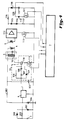
- Figure 4 illustrates schematically an electronic circuitry of the device according to the invention.
- the device comprises a first circuitry 1 and a second circuitry 2.
- the first circuitry 1 comprises a primary coil 10 and switching means 12, for connecting the primary coil 10 for a period of time to a power source, in particular to a battery 3 such as to accumulate a predetermined amount of magnetic energy in the primary coil 10.
- the second circuitry 2 comprises a light emitting diode (LED) 4 and a secondary coil 11 which is magnetically coupled to the primary coil 10. This can be done by disposing both coils around a same core, for example around the two legs of a closed U-shaped core. Preference is however given to disposing both coils over one another around the same core 5. In this way, energy losses can be restricted to a minimum.
- LED light emitting diode
- the primary and secondary coils 10 and 11 have the same winding direction, but it is clear that they may have alternatively opposite winding directions.
- a current i1 flows through the primary coil 10 as shown in Figure 1
- a voltage will be generated in the secondary coil 11, having the polarity indicated by 6, but due to the direction of the LED 4
- no current can flow in the second circuitry.
- opening the switching means 12 as shown in Figure 2 the current i1 through the primary coil 10 and thus also the magnetic field generated thereby drops suddenly to 0, as a result of which an electromotive force is generated by mutual induction in the secondary coil 11.
- This electromotive force has the opposite polarity of the electromotive force generated when the magnetic energy was accumulated in the coils so that a current i2 can now flow through the LED 4.
- the magnetic energy is very quickly transformed by mutual induction into an electrical pulse in the second circuitry 2.
- the number of windings n1 in the primary coil 10 is higher than the number of windings n2 in the secondary coil 11, allowing to generate electrical pulses of a higher current level than the electrical current supplied by the power source 3 to the primary coil 10.
- the proportion of the number of windings n1 in the primary coil 10 to the number of windings n2 in the secondary coil 11 is at least equal to about 100, and the primary coil has a number of windings of at least about 300. This enables to transform the accumulated energy into a high peak current and this during a short period of time.
- the generated pulses should more particularly have a raising edge of a duration which is preferably shorter than 10 ⁇ sec.
- the core 5 connecting the primary coil with the secondary coil is a ferrite core, since such a material shows adequate hysteresis properties which enable to restrict the energy losses to a minimum and which further enable to achieve the required short pulse duration.
- a device with the following parameters has been chosen : a battery of 9V, number of windings n1 in the primary coil 10 equal to 707, and number of windings n2 in the secondary coil 11 equal to 5, the core being a ferrite core.
- Figure 3 illustrates the current flow in the first, respectively the second circuitry.
- a current i1 flows in the first circuitry 1 which increases due to the presence of the primary coil 10 linearly in time.
- a peak current i2 having a short duration, more particularly a raising edge of only about 2 ⁇ sec, flows in the second circuitry 2 and thus through the LED 4.
- the current in the first circuitry was 0 mA at t1 and 20 mA at t2, while t2-t1 was equal to 366 ⁇ sec. From the Lenz law, it can now be deduced that in case the energy losses are negligible, the self induction L1 in the primary coil 10 is equal to : 9 V *366*10 -6 s 20*10 -3 A ⁇ 0.165 Henry
- the amount of energy E in the first circuitry is equal to the amount of energy E in the second circuitry.
- i1 max is the maximum current in the first circuitry
- i2 max is the maximum current in the second circuitry.
- k is k equal to about 141 and i1 max to about 20mA so that i2 max will be approximately equal to about 2.8A.
- the battery provides also current to the periphery, which is not taken into consideration herein.
- Figure 4 illustrates schematically an electronic circuitry in a particular embodiment of the device according to the invention.
- the following table gives the identification or component values of components indicated in Figure 4 by a reference numeral.
- the switching means 12 are opened and closed for disconnecting and connecting the primary coil 10 for a period of time to the battery 3, as explained hereinabove.
- switching means 12 use is made of a cascode circuit 106-111 comprising a transistor 110, resistors 106 and 107, a capacitor 108, a diode 109 and a mosfet 111, such as illustrated in Figure 4.
- a cascode circuit which is also known as emitter switching, is known per se and allows to switch the transistor 110 very quickly on and off, which is required to resist to high voltage peak values.
- Transistor 110 can resist to the high voltage peak values, which is caused by the primary coil 10 when opening the switching means, while mosfet 111, due to the other elements of the cascode circuit, must only resists to a voltage of 5V supplied by a voltage regulator 8.
- the circuit comprises resistance 102 and diodes 100 and 101 in such a configuration that, in case the battery is not inserted in the right position, the generated inverse voltage is clamped to -0.7 Volts by diode 101, protecting the entire circuit from inverse polarity.
- Capacitors 104 and 105 are connected as buffer capacity for outputting an activation signal, for example for opening and closing a valve in case the device according to the invention is used for an automatic faucet device.
- the primary and secondary coils 10 and 11 are wound around the same ferrite core 5, as explained hereinabove.
- the light emitting diode 4 When an electrical pulse is generated, as explained hereinabove, the light emitting diode 4 emits an infra-red light beam in the target area. If an object is present in this target area, the presence of this object will be detected by means of a receiver 9 for the emitted light beam. This can be done in different ways. According to a first embodiment, the emitted signal is reflected by the object back towards the receiver 9. In case the object to be detected is for example an object of a dark colour such as dirty hands or a person wearing a dark suit, the reflected signal will have a substantially lower amplitude than the emitted signal.
- the device according to the invention it is very important to have a good detection which can be achieved by the device according to the invention due to the fact that it allows to emit signals of a higher amplitude without requiring more energy.
- the signal emitted from the LED is transmitted towards a receiver, either directly or through the intermediary of a reflector.
- the presence of an object is in this case detected when the emitted signal is interrupted by the object and does not reach the receiver any more or with a too low amplitude.
- the receiver 9 When the receiver 9 receives the emitted light beam, it generates a signal which is amplified by amplifier 112, passes through resistance 114 and diode 118 and charges capacitor 122. Resistance 120, diode 119 and mosfet 121 are used to discharge capacitor 122, under control of the microcontroller 7. Capacitor 122 can thus be considered as a memory, which is charged with a signal when an object is present in the target area. Under control of the microcontroller 7, the content of the capacitor 122 is read and the capacitor 122 is discharged.
- Resistance 117 is a pull-down load resistor for amplifier 112. Diodes 115 and 116 create a voltage offset to match the microcontroller voltage level requirements.
- mosfet 113 is used to enable amplifier 112 only when a light signal is emitted.
- the periphery of the device according to the invention is preferably for about 70% of the time in stand-by or sleepmode.
- the device according to the invention may further comprise means for measuring the voltage of the battery.
- means for measuring the voltage of the battery are known per se, for example from EP-B-0 423 102.
- further means are provided, for example in the microcontroller, for determining the period of time required to accumulate the predetermined amount of magnetic energy on the basis of the measured voltage of the battery.
- Timer means may also be provided, for example in the microcontroller for closing said switching means each time for said period of time.
- a further function of the voltage measurement is for generating buzzer signals to inform the user that the battery has lost a predetermined amount of voltage and that the battery has to be replaced. This is described in detail in EP-B-0 423 102, which is incorporated herein by way of reference.
- the present invention relates to a low voltage proximity detecting device for detecting an object in a target area.
- This device is provided with means providing electrical pulses having a relatively high energy level but a short duration. This enables the device according to the invention to require less energy to emit light pulses, but covering a similar or even greater target area, and allowing to emit stronger light pulses to obtain a better detection.
- the device according to the invention can i.a. be used as an automatic control system for bathroom fittings such as urinals or toilets, but also for example for automatic door opening systems.
- a battery has been used as low voltage source. It is however clear that the use of other low voltage sources, such as photo cells, can also be taken into consideration, especially in case they have to provide only energy for the detecting device as such, including the microprocessor.
Landscapes
- Engineering & Computer Science (AREA)
- Physics & Mathematics (AREA)
- Computer Networks & Wireless Communication (AREA)
- General Physics & Mathematics (AREA)
- Radar, Positioning & Navigation (AREA)
- Remote Sensing (AREA)
- Electromagnetism (AREA)
- Geophysics And Detection Of Objects (AREA)
- Domestic Plumbing Installations (AREA)
- Switches That Are Operated By Magnetic Or Electric Fields (AREA)
- Measuring Pulse, Heart Rate, Blood Pressure Or Blood Flow (AREA)
Claims (8)
- Dispositif de détection de proximité pour détecter la présence d'un objet dans une aire visée, comprenant une source d'énergie basse tension (3), un montage comprenant un moyen de commutation (12) pour produire des impulsions électriques et agencé pour amener ces impulsions électriques à une diode électroluminescente (4) afin d'émettre des impulsions lumineuses, et un récepteur (9) pour la réception des impulsions lumineuses émises de la diode électroluminescente (4) et dirigées vers l'aire visée susdite, ledit récepteur (9) étant agencé pour recevoir lesdites impulsions lumineuses après réflexion sur un ou plusieurs réflecteurs ou après réflexion sur l'objet à détecter, caractérisé en ce que ledit montage comprend un premier montage (1) comprenant une bobine primaire (10) et ledit moyen de commutation (12), qui sont agencés pour connecter la bobine primaire (10) pendant une certaine période de temps à la source d'énergie basse tension (3) de manière à accumuler une quantité prédéterminée d'énergie magnétique dans la bobine primaire (10), et un second montage (2) contenant la diode électroluminescente (4) et une bobine secondaire (11) couplée magnétiquement à la bobine primaire (10) pour transformer l'énergie magnétique accumulée par induction mutuelle lors de l'ouverture du moyen de commutation (12) chaque fois en l'une de ces impulsions électriques, ledit récepteur étant agencé alternativement pour recevoir les impulsions lumineuses précitées directement sans réflexion de la cible.
- Dispositif suivant la revendication 1, caractérisé en ce que la proportion du nombre d'enroulements de la bobine primaire (10) au nombre d'enroulements de la bobine secondaire (11) est au moins égale à environ 100.
- Dispositif suivant l'une ou l'autre des revendications 1 et 2, caractérisé en ce que les impulsions électriques susdites ont un bord d'élévation d'une durée inférieure à 10 µsec.
- Dispositif suivant l'une quelconque des revendications 1 à 3, caractérisé en ce que les bobines primaire et secondaire (10, 11) sont enroulées l'une sur l'autre autour d'un même noyau (5).
- Dispositif suivant la revendication 4, caractérisé en ce que ledit noyau (5) est un noyau en ferrite.
- Dispositif suivant l'une quelconque des revendications 1 à 5, caractérisé en ce que la bobine primaire (10) a un nombre d'enroulements au moins égal à environ 300.
- Dispositif suivant l'une quelconque des revendications 1 à 6, caractérisé en ce qu'il comprend un moyen pour déterminer la tension de la source d'énergie basse tension (3), un moyen pour déterminer la période de temps requise pour accumuler la quantité prédéterminée d'énergie magnétique précitée sur la base de la tension de la source d'énergie basse tension (3) et un moyen de minuterie pour fermer le moyen de commutation (12) chaque fois pendant ladite période de temps.
- Dispositif suivant l'une quelconque des revendications 1 à 7, caractérisé en ce que le moyen de commutation (12) comprend un circuit en cascode.
Priority Applications (4)
| Application Number | Priority Date | Filing Date | Title |
|---|---|---|---|
| EP19960201635 EP0813075B1 (fr) | 1996-06-12 | 1996-06-12 | Dispositif de détection de proximité |
| DE69600972T DE69600972T2 (de) | 1996-06-12 | 1996-06-12 | Vorrichtung zur Feststellung von Annäherungen |
| AT96201635T ATE173339T1 (de) | 1996-06-12 | 1996-06-12 | Vorrichtung zur feststellung von annäherungen |
| US08/867,597 US5963135A (en) | 1996-06-12 | 1997-05-30 | Proximity detecting device |
Applications Claiming Priority (1)
| Application Number | Priority Date | Filing Date | Title |
|---|---|---|---|
| EP19960201635 EP0813075B1 (fr) | 1996-06-12 | 1996-06-12 | Dispositif de détection de proximité |
Publications (2)
| Publication Number | Publication Date |
|---|---|
| EP0813075A1 EP0813075A1 (fr) | 1997-12-17 |
| EP0813075B1 true EP0813075B1 (fr) | 1998-11-11 |
Family
ID=8224071
Family Applications (1)
| Application Number | Title | Priority Date | Filing Date |
|---|---|---|---|
| EP19960201635 Expired - Lifetime EP0813075B1 (fr) | 1996-06-12 | 1996-06-12 | Dispositif de détection de proximité |
Country Status (4)
| Country | Link |
|---|---|
| US (1) | US5963135A (fr) |
| EP (1) | EP0813075B1 (fr) |
| AT (1) | ATE173339T1 (fr) |
| DE (1) | DE69600972T2 (fr) |
Cited By (2)
| Publication number | Priority date | Publication date | Assignee | Title |
|---|---|---|---|---|
| WO2004109920A1 (fr) * | 2003-06-04 | 2004-12-16 | Liteforce Pty Ltd | Interrupteur telecommande |
| EP1160383B1 (fr) * | 1996-02-28 | 2006-06-21 | N.V. INTERNATIONAL SANITARY WARE-MANUFACTURING CY, S.A. in verkort: N.V. INTERSAN S.A. | Dispositif pour commander une série d'appareils pour salle d'eau |
Families Citing this family (20)
| Publication number | Priority date | Publication date | Assignee | Title |
|---|---|---|---|---|
| EP0926512B1 (fr) * | 1997-12-17 | 2006-03-08 | Inter Company Computer, Engineering, Design Services, in het kort : " Concept Design", naamloze vennootschap | Dispositif de détection de proximité |
| US6392547B1 (en) * | 1999-11-26 | 2002-05-21 | Microgistics, Inc. | Proximity monitoring system and associated methods |
| US6484974B1 (en) | 2001-09-10 | 2002-11-26 | Union Switch & Signal, Inc. | Controller for switch machine |
| WO2005016647A2 (fr) * | 2003-08-14 | 2005-02-24 | Nicodem Harry E | Appareil de remplissage de cartouches d'imprimante a jet d'encre et procedes associes |
| BRPI0519763B1 (pt) * | 2004-12-30 | 2018-10-23 | Colman Group Inc | distribuidor aperfeiçoado para material laminado |
| CN101035455A (zh) * | 2005-07-26 | 2007-09-12 | 三菱电机株式会社 | 手干燥装置 |
| US20070188178A1 (en) * | 2006-02-10 | 2007-08-16 | Dietz Paul H | Apparatus and method for sensing objects proximate to fluid flows |
| CN1862249B (zh) * | 2006-04-20 | 2012-01-04 | 上海科勒电子科技有限公司 | 干电池供电主动式红外感应器具的节能处理方法 |
| ES2629803T3 (es) * | 2007-10-22 | 2017-08-14 | San Jamar, Inc. | Dispensador de material en banda con función de diferenciación |
| WO2011133157A1 (fr) | 2010-04-22 | 2011-10-27 | The Colman Group, Inc. | Insert à utiliser avec un rouleau de tissu et conférant un identifiant unique pour le rouleau de tissu |
| US20120218115A1 (en) * | 2010-11-05 | 2012-08-30 | John Gerard Chupa | Back looking warning assembly and a method for determining the presence of a tangible entity in close proximity to the back of an individual |
| US9536389B2 (en) | 2010-11-15 | 2017-01-03 | Bally Gaming, Inc. | Wager recognition system having ambient light sensor and related method |
| US9142084B2 (en) | 2010-11-15 | 2015-09-22 | Bally Gaming, Inc. | Wager recognition system |
| USD802326S1 (en) | 2011-09-14 | 2017-11-14 | San Jamar, Inc. | Insert for a web material dispenser |
| WO2015164523A1 (fr) * | 2014-04-23 | 2015-10-29 | Bally Gaming, Inc. | Système de reconnaissance de pari comportant un capteur de lumière ambiante et procédé associé |
| US10009025B2 (en) * | 2014-05-22 | 2018-06-26 | S.T.S.R. S.R.L. | Detection sensor |
| US9858752B2 (en) | 2014-12-23 | 2018-01-02 | Bally Gaming, Inc. | Method and system for side wagering |
| US11354997B2 (en) | 2016-11-30 | 2022-06-07 | Meliah Kearse | Proximity warning assembly |
| USD860674S1 (en) | 2018-02-06 | 2019-09-24 | San Jamar, Inc. | Towel dispenser |
| USD904066S1 (en) | 2019-09-19 | 2020-12-08 | Georgia-Pacific LLC | Core plug |
Family Cites Families (9)
| Publication number | Priority date | Publication date | Assignee | Title |
|---|---|---|---|---|
| DE2642216C2 (de) * | 1976-09-20 | 1982-04-15 | Messwandler-Bau Gmbh, 8600 Bamberg | Spannungstransformator mit stabförmigem Eisenkern zur Verwendung als Ankopplungstransformator für Netzwerke mit überlagerter Tonfrequenzspannung, insbesondere Rundsteueranlagen |
| US4472661A (en) * | 1982-09-30 | 1984-09-18 | Culver Clifford T | High voltage, low power transformer for efficiently firing a gas discharge luminous display |
| DE3303404C1 (de) * | 1983-02-02 | 1984-04-05 | Leuze electronic GmbH + Co, 7311 Owen | Verfahren zur Erzeugung der für den Betrieb von eine Strahlung emittierenden Halbleiterdioden erforderlichen Stromimpulse und Anordnung zur Durchführung des Verfahrens |
| EP0143795A4 (fr) * | 1983-04-13 | 1987-01-20 | Auto Aqua Proprietary Ltd | Systeme de robinet. |
| US4626849A (en) * | 1983-07-29 | 1986-12-02 | Sims John C | Proximity detection system |
| US4625155A (en) * | 1984-12-03 | 1986-11-25 | Rca Corporation | Resonant switching apparatus using a cascode arrangement |
| US5086526A (en) * | 1989-10-10 | 1992-02-11 | International Sanitary Ware Manufacturin Cy, S.A. | Body heat responsive control apparatus |
| ES2105089T3 (es) * | 1993-01-04 | 1997-10-16 | Philips Electronics Nv | Circuito suministrador de energia. |
| US5566702A (en) * | 1994-12-30 | 1996-10-22 | Philipp; Harald | Adaptive faucet controller measuring proximity and motion |
-
1996
- 1996-06-12 EP EP19960201635 patent/EP0813075B1/fr not_active Expired - Lifetime
- 1996-06-12 DE DE69600972T patent/DE69600972T2/de not_active Expired - Lifetime
- 1996-06-12 AT AT96201635T patent/ATE173339T1/de not_active IP Right Cessation
-
1997
- 1997-05-30 US US08/867,597 patent/US5963135A/en not_active Expired - Fee Related
Cited By (2)
| Publication number | Priority date | Publication date | Assignee | Title |
|---|---|---|---|---|
| EP1160383B1 (fr) * | 1996-02-28 | 2006-06-21 | N.V. INTERNATIONAL SANITARY WARE-MANUFACTURING CY, S.A. in verkort: N.V. INTERSAN S.A. | Dispositif pour commander une série d'appareils pour salle d'eau |
| WO2004109920A1 (fr) * | 2003-06-04 | 2004-12-16 | Liteforce Pty Ltd | Interrupteur telecommande |
Also Published As
| Publication number | Publication date |
|---|---|
| DE69600972D1 (de) | 1998-12-17 |
| US5963135A (en) | 1999-10-05 |
| ATE173339T1 (de) | 1998-11-15 |
| DE69600972T2 (de) | 1999-06-17 |
| EP0813075A1 (fr) | 1997-12-17 |
Similar Documents
| Publication | Publication Date | Title |
|---|---|---|
| EP0813075B1 (fr) | Dispositif de détection de proximité | |
| US6215116B1 (en) | Continuous threshold adjustable proximity detecting device | |
| US5465094A (en) | Two terminal micropower radar sensor | |
| US6509658B1 (en) | Device for the automatic shut-off of equipment's stand-by power | |
| KR940007080B1 (ko) | 부하 제어 시스템 | |
| KR900008388B1 (ko) | 잡음 면역성 전류 감지 장치 부착 전원 공급기 | |
| US4260943A (en) | High frequency battery charger | |
| CA2292848A1 (fr) | Appareillage ameliore pour la detection d'ecoulement de fluide et circuit connexe de regulation de charge | |
| JPS62156446A (ja) | 給水制御装置 | |
| US5508878A (en) | Electronic timer using zero power while off | |
| US5748074A (en) | Electronic door chime | |
| JPS633538B2 (fr) | ||
| US6575120B1 (en) | Animal control system | |
| US20010035134A1 (en) | Animal control system | |
| US20170213428A1 (en) | Wireless door chime extension | |
| CA2339930C (fr) | Dispositif destine a une barriere electrique | |
| US4263665A (en) | Ultrasonic intrusion alarm system | |
| US5465033A (en) | Universal safety system for automatic doors | |
| US6459381B2 (en) | Apparatus for detecting operation of an electric fence and fence charger | |
| US5196735A (en) | Circuit arrangement | |
| EP0388882B1 (fr) | Agencement de circuits | |
| US20020003688A1 (en) | System for monitoring power consumers in an electrical circuit | |
| KR980006398U (ko) | 충전식 전동칫솔의 프리볼트 무선충전기 전자회로 | |
| JP2847464B2 (ja) | 給水制御装置 | |
| AU785408B2 (en) | Apparatus for detecting operation of an electric fence |
Legal Events
| Date | Code | Title | Description |
|---|---|---|---|
| PUAI | Public reference made under article 153(3) epc to a published international application that has entered the european phase |
Free format text: ORIGINAL CODE: 0009012 |
|
| 17P | Request for examination filed |
Effective date: 19970114 |
|
| AK | Designated contracting states |
Kind code of ref document: A1 Designated state(s): AT BE CH DE FR GB IT LI LU NL |
|
| AX | Request for extension of the european patent |
Free format text: AL;LT;LV;SI |
|
| GRAG | Despatch of communication of intention to grant |
Free format text: ORIGINAL CODE: EPIDOS AGRA |
|
| RBV | Designated contracting states (corrected) |
Designated state(s): AT BE CH DE FR GB IT LI LU NL |
|
| GRAG | Despatch of communication of intention to grant |
Free format text: ORIGINAL CODE: EPIDOS AGRA |
|
| GRAH | Despatch of communication of intention to grant a patent |
Free format text: ORIGINAL CODE: EPIDOS IGRA |
|
| GRAH | Despatch of communication of intention to grant a patent |
Free format text: ORIGINAL CODE: EPIDOS IGRA |
|
| GRAA | (expected) grant |
Free format text: ORIGINAL CODE: 0009210 |
|
| AK | Designated contracting states |
Kind code of ref document: B1 Designated state(s): AT BE CH DE FR GB IT LI LU NL |
|
| REF | Corresponds to: |
Ref document number: 173339 Country of ref document: AT Date of ref document: 19981115 Kind code of ref document: T |
|
| REG | Reference to a national code |
Ref country code: CH Ref legal event code: EP |
|
| REF | Corresponds to: |
Ref document number: 69600972 Country of ref document: DE Date of ref document: 19981217 |
|
| REG | Reference to a national code |
Ref country code: CH Ref legal event code: NV Representative=s name: R. A. EGLI & CO. PATENTANWAELTE |
|
| ITF | It: translation for a ep patent filed | ||
| ET | Fr: translation filed | ||
| PLBE | No opposition filed within time limit |
Free format text: ORIGINAL CODE: 0009261 |
|
| STAA | Information on the status of an ep patent application or granted ep patent |
Free format text: STATUS: NO OPPOSITION FILED WITHIN TIME LIMIT |
|
| 26N | No opposition filed | ||
| REG | Reference to a national code |
Ref country code: GB Ref legal event code: IF02 |
|
| PG25 | Lapsed in a contracting state [announced via postgrant information from national office to epo] |
Ref country code: IT Free format text: LAPSE BECAUSE OF NON-PAYMENT OF DUE FEES Effective date: 20050612 |
|
| PGFP | Annual fee paid to national office [announced via postgrant information from national office to epo] |
Ref country code: LU Payment date: 20100621 Year of fee payment: 15 Ref country code: FR Payment date: 20100506 Year of fee payment: 15 |
|
| PGFP | Annual fee paid to national office [announced via postgrant information from national office to epo] |
Ref country code: NL Payment date: 20100426 Year of fee payment: 15 Ref country code: AT Payment date: 20100614 Year of fee payment: 15 |
|
| PGFP | Annual fee paid to national office [announced via postgrant information from national office to epo] |
Ref country code: CH Payment date: 20100623 Year of fee payment: 15 Ref country code: BE Payment date: 20100518 Year of fee payment: 15 |
|
| PGFP | Annual fee paid to national office [announced via postgrant information from national office to epo] |
Ref country code: GB Payment date: 20100618 Year of fee payment: 15 Ref country code: DE Payment date: 20100625 Year of fee payment: 15 |
|
| BERE | Be: lapsed |
Owner name: INTER CY COMPUTER ENGINEERING DESIGN SERVICES *CON Effective date: 20110630 |
|
| REG | Reference to a national code |
Ref country code: NL Ref legal event code: V1 Effective date: 20120101 |
|
| REG | Reference to a national code |
Ref country code: CH Ref legal event code: PL |
|
| GBPC | Gb: european patent ceased through non-payment of renewal fee |
Effective date: 20110612 |
|
| PG25 | Lapsed in a contracting state [announced via postgrant information from national office to epo] |
Ref country code: AT Free format text: LAPSE BECAUSE OF NON-PAYMENT OF DUE FEES Effective date: 20110612 |
|
| REG | Reference to a national code |
Ref country code: AT Ref legal event code: MM01 Ref document number: 173339 Country of ref document: AT Kind code of ref document: T Effective date: 20110612 |
|
| REG | Reference to a national code |
Ref country code: FR Ref legal event code: ST Effective date: 20120229 |
|
| PG25 | Lapsed in a contracting state [announced via postgrant information from national office to epo] |
Ref country code: BE Free format text: LAPSE BECAUSE OF NON-PAYMENT OF DUE FEES Effective date: 20110630 |
|
| REG | Reference to a national code |
Ref country code: DE Ref legal event code: R119 Ref document number: 69600972 Country of ref document: DE Effective date: 20120103 |
|
| PG25 | Lapsed in a contracting state [announced via postgrant information from national office to epo] |
Ref country code: LI Free format text: LAPSE BECAUSE OF NON-PAYMENT OF DUE FEES Effective date: 20110630 Ref country code: CH Free format text: LAPSE BECAUSE OF NON-PAYMENT OF DUE FEES Effective date: 20110630 Ref country code: FR Free format text: LAPSE BECAUSE OF NON-PAYMENT OF DUE FEES Effective date: 20110630 Ref country code: DE Free format text: LAPSE BECAUSE OF NON-PAYMENT OF DUE FEES Effective date: 20120103 |
|
| PG25 | Lapsed in a contracting state [announced via postgrant information from national office to epo] |
Ref country code: NL Free format text: LAPSE BECAUSE OF NON-PAYMENT OF DUE FEES Effective date: 20120101 |
|
| PG25 | Lapsed in a contracting state [announced via postgrant information from national office to epo] |
Ref country code: GB Free format text: LAPSE BECAUSE OF NON-PAYMENT OF DUE FEES Effective date: 20110612 |
|
| PG25 | Lapsed in a contracting state [announced via postgrant information from national office to epo] |
Ref country code: LU Free format text: LAPSE BECAUSE OF NON-PAYMENT OF DUE FEES Effective date: 20110612 |