EP0813100A2 - Appareil photo et cartouche de film - Google Patents
Appareil photo et cartouche de film Download PDFInfo
- Publication number
- EP0813100A2 EP0813100A2 EP97108993A EP97108993A EP0813100A2 EP 0813100 A2 EP0813100 A2 EP 0813100A2 EP 97108993 A EP97108993 A EP 97108993A EP 97108993 A EP97108993 A EP 97108993A EP 0813100 A2 EP0813100 A2 EP 0813100A2
- Authority
- EP
- European Patent Office
- Prior art keywords
- film
- lens
- photographic camera
- lens slide
- body shell
- Prior art date
- Legal status (The legal status is an assumption and is not a legal conclusion. Google has not performed a legal analysis and makes no representation as to the accuracy of the status listed.)
- Withdrawn
Links
- 230000036316 preload Effects 0.000 claims description 6
- 238000010304 firing Methods 0.000 claims description 5
- 230000000284 resting effect Effects 0.000 claims description 2
- 230000007704 transition Effects 0.000 claims 1
- 238000010276 construction Methods 0.000 description 3
- 238000000034 method Methods 0.000 description 3
- 230000006835 compression Effects 0.000 description 2
- 238000007906 compression Methods 0.000 description 2
- 238000006073 displacement reaction Methods 0.000 description 1
- 238000001746 injection moulding Methods 0.000 description 1
- 230000000717 retained effect Effects 0.000 description 1
- 230000001960 triggered effect Effects 0.000 description 1
Images




Classifications
-
- G—PHYSICS
- G03—PHOTOGRAPHY; CINEMATOGRAPHY; ANALOGOUS TECHNIQUES USING WAVES OTHER THAN OPTICAL WAVES; ELECTROGRAPHY; HOLOGRAPHY
- G03B—APPARATUS OR ARRANGEMENTS FOR TAKING PHOTOGRAPHS OR FOR PROJECTING OR VIEWING THEM; APPARATUS OR ARRANGEMENTS EMPLOYING ANALOGOUS TECHNIQUES USING WAVES OTHER THAN OPTICAL WAVES; ACCESSORIES THEREFOR
- G03B19/00—Cameras
- G03B19/02—Still-picture cameras
- G03B19/04—Roll-film cameras
-
- G—PHYSICS
- G03—PHOTOGRAPHY; CINEMATOGRAPHY; ANALOGOUS TECHNIQUES USING WAVES OTHER THAN OPTICAL WAVES; ELECTROGRAPHY; HOLOGRAPHY
- G03B—APPARATUS OR ARRANGEMENTS FOR TAKING PHOTOGRAPHS OR FOR PROJECTING OR VIEWING THEM; APPARATUS OR ARRANGEMENTS EMPLOYING ANALOGOUS TECHNIQUES USING WAVES OTHER THAN OPTICAL WAVES; ACCESSORIES THEREFOR
- G03B1/00—Film strip handling
- G03B1/02—Moving film strip by pull on end thereof
- G03B1/04—Pull exerted by take-up spool
- G03B1/08—Pull exerted by take-up spool rotated by band, chain, rack, or other linear reciprocating operation
-
- G—PHYSICS
- G03—PHOTOGRAPHY; CINEMATOGRAPHY; ANALOGOUS TECHNIQUES USING WAVES OTHER THAN OPTICAL WAVES; ELECTROGRAPHY; HOLOGRAPHY
- G03B—APPARATUS OR ARRANGEMENTS FOR TAKING PHOTOGRAPHS OR FOR PROJECTING OR VIEWING THEM; APPARATUS OR ARRANGEMENTS EMPLOYING ANALOGOUS TECHNIQUES USING WAVES OTHER THAN OPTICAL WAVES; ACCESSORIES THEREFOR
- G03B17/00—Details of cameras or camera bodies; Accessories therefor
- G03B17/02—Bodies
- G03B17/04—Bodies collapsible, foldable or extensible, e.g. book type
-
- G—PHYSICS
- G03—PHOTOGRAPHY; CINEMATOGRAPHY; ANALOGOUS TECHNIQUES USING WAVES OTHER THAN OPTICAL WAVES; ELECTROGRAPHY; HOLOGRAPHY
- G03B—APPARATUS OR ARRANGEMENTS FOR TAKING PHOTOGRAPHS OR FOR PROJECTING OR VIEWING THEM; APPARATUS OR ARRANGEMENTS EMPLOYING ANALOGOUS TECHNIQUES USING WAVES OTHER THAN OPTICAL WAVES; ACCESSORIES THEREFOR
- G03B17/00—Details of cameras or camera bodies; Accessories therefor
- G03B17/26—Holders for containing light sensitive material and adapted to be inserted within the camera
-
- G—PHYSICS
- G03—PHOTOGRAPHY; CINEMATOGRAPHY; ANALOGOUS TECHNIQUES USING WAVES OTHER THAN OPTICAL WAVES; ELECTROGRAPHY; HOLOGRAPHY
- G03B—APPARATUS OR ARRANGEMENTS FOR TAKING PHOTOGRAPHS OR FOR PROJECTING OR VIEWING THEM; APPARATUS OR ARRANGEMENTS EMPLOYING ANALOGOUS TECHNIQUES USING WAVES OTHER THAN OPTICAL WAVES; ACCESSORIES THEREFOR
- G03B17/00—Details of cameras or camera bodies; Accessories therefor
- G03B17/42—Interlocking between shutter operation and advance of film or change of plate or cut-film
Definitions
- the invention relates to a photographic camera of small, flat design, consisting of a body shell, a taking lens, a viewfinder, a film chamber, film transport means, and a flash device.
- a camera of this kind is known from DE-OS 30 19 307.
- This document discloses a photographic camera with a lens, an image stage, and a rear cover, for use of a flat, pocket-like film cassette which contains a light-sensitive film strip, suitable for taking a plurality of pictures, that can be moved out of and into the cassette through a film mouth provided on one narrow side of the cassette.
- a cassette space is provided between the camera rear cover and a cassette support configured on a camera body shell.
- a film receiving space is arranged parallel to this, between the surface of the camera body shell parallel to the cassette support and a wall of the camera housing lying opposite to the camera rear cover and comprising the lens and image stage.
- the film transport means are mounted on the camera body in the region of the extension of the cassette supports. They are configured as a perforation gear with two rows of teeth.
- the body shell is configured parallelepipedally and has on its front side a linear flat guideway in which a lens slide is guided displaceably from a non-operating position into a taking position and for purposes of film transport; and that the film chamber is arranged on the back side of the body shell.
- the body shell also has a linear flat guideway on the back side, and the film chamber is configured as a replaceable cassette that is displaceably guided in the flat guideway.
- the lens slide which is displaceable from the non-operating position into the taking position, can be snap-locked into the latter, and in this taking position the viewfinder is uncovered and the lens is in its taking position.
- a lens carrier receiving the lens is guided in the lens slide perpendicular to the movement direction of the lens slide, and is movable from a non-operating position into a taking position and vice versa.
- a film cassette for the photographic camera in question to receive a film strip equipped with an edge perforation, and consists of a flat, parallelepipedal housing with an exposure window and a film mouth, and is characterized in that configured in the housing is a circumferential, continuous film channel extending in the longitudinal direction thereof, which passes by the exposure window and opens into the film mouth.
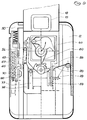
- Subminiature camera 11 illustrated in the drawings consists of a flat body shell 12 on whose front side a lens slide 18 with a lens carrier 13 is slidable in a flat guideway 17 from a non-operating position into a taking position.
- a lens 14 is set into lens carrier 13.
- a viewfinder 15 and a flash arrangement 16 are provided in lens slide 18.
- Lens carrier 13 is pretensioned in lens slide 18, by means of a return spring 19, against a housing-side ramp 39 and a support surface 40.
- film cassette 10 On the back side of subminiature camera 11, film cassette 10 is guided, again by means of a flat guideway 23, in body shell 12 so as to slide in and out, and is held in its end positions.
- the configuration of film cassette 10 will be described in further detail following the description of the construction of the camera.
- a release button 50 is guided longitudinally displaceably parallel to lens slide 18 against the force of a return spring 51.
- Release button 50 engages with a projection 52 on one arm 53 of a two-armed release pawl 54 mounted pivotedly in lens slide 18, when lens slide 18 is in its taking position.
- the other arm 55 of release pawl 54 is braced against a surface 56 of an impact lever 58 that is preloaded by a drive spring 57.
- Impact lever 58 rests with an impact arm 59 against a shutter blade 60 that is held, under the preload of a torsion spring 61, in its closed position in front of lens 14.
- the impact lever has a cam 62 whose purpose will be described later.
- a retaining lever 63 which is braced elastically on arm 55 by means of a lobe 64, is mounted pivotedly in lens slide 18 parallel to arm 55 of release pawl 54.
- a counter lever 65 which is guided displaceably in body shell 12 in a pin-and-oblong-hole guide and engages in spring-loaded fashion, with a pawl 66 configured at its free end, into the teeth of a counter bar 67.
- counter bar 67 is designed with eight teeth for eight photographic images, and equipped accordingly with the digits 8 to 1 to count the remaining pictures.
- a stop 68 delimits movement after the eighth picture is taken, and a compression spring returns counter bar 67 to its zero position.
- a hook 74 provided on counter lever 65 and interacting with a gate 80 on film cassette 10, serves to disengage the latter from the teeth of counter bar 67 when film cassette 10 is changed.
- a detent pawl 70 which on the one hand engages with a pawl-shaped lug 71 into the teeth of counter bar 67 and on the other hand lies with an end surface 72 at a short distance opposite the side surface of lens slide 18, is mounted pivotedly in body shell 12. With lens slide 18 in either the non-operating or the taking position, there is thus located opposite end surface 72 a cutout 93 or 73 present in the side surface thereof, into which end surface 72 penetrates when film cassette 10 is changed. For this purpose, a hook 75 which cooperates with gate 80 on film cassette 10 is also provided on detent pawl 70.
- a film gripper 76 which engages by means of a spring arm 77 and a snap ball 78 arranged at its free end into a snap recess 79 configured on lens slide 18, is guided so as to be displaced longitudinally with lens slide 18 in body shell 12. This engagement persists so long as lens slide 18 is moved only for the purpose of film transport after a picture has been taken. Only when lens slide 18 is slid back into its non-operating position does this snap connection 78/79 release and film gripper 76 remain in a position in which film gripper 76 comes into contact with its gripper tooth 81 against a stop shoulder 82 configured in film cassette 10.
- This cam 62 additionally actuates flash arrangement 16 when the camera is triggered.
- cam 82 strikes a retaining pawl 84 which releases a firing spring 85 that strikes a piezo block 86.
- a flash lamp is fired via electrical lines 87 that end in a socket 88 of flash arrangement 16.
- leg spring 89 that rests with one leg against body shell 12 and with the other leg, whose end is paddle-shaped, under spring preload against the side wall of lens slide 18 in its non-operating position, is arranged in body shell 12.
- a shoulder 90 Configured on lens slide 18 and lying transverse to its movement direction is a shoulder 90 against which leg spring 89 rests with its paddle-shaped end when lens slide 18 is displaced into its taking position, and assists that displacement. In the taking position, leg spring 89 secures the position of lens slide 18.
- film cassette 10 consists of a flat, parallelepipedal housing 20 in which a continuous film channel 21 is provided.
- Film channel 21 is constituted by two longitudinal sections 21a and 21b extending parallel to one another, as well as semicircular sections 21c and 21d joining their ends.
- housing 20 has an outer wall 22 in which a flat guideway 23 associated with camera-side flat guideway 17 is configured.
- Parallel to section 21b of film channel 21, housing 20 has an outer wall 45.
- an exposure window 24 communicating with film channel section 21a is present in outer wall 22.
- a recess 25 Provided between film channel section 21a and exposure window 24 is a recess 25 extending over the latter, in which a spring-loaded shutter panel 26 is mounted longitudinally displaceably to close off exposure window 24 when not joined to a camera.
- a pin 27 that interacts with a camera-side stop in order to open shutter panel 26 is mounted on shutter panel 26.
- the inner walls of film channel 21 are constituted by a web 28 that, for reasons related to injection molding, is configured as a hollow web.
- a wall section 29 of housing 20 is arranged in the region of semicircular film channel section 21d, separated from outer wall 22 and configured as a film hinge by the fact that a constriction 30 is provided in that wall section 29.
- the free end of wall section 29 is configured as a lip and rests, in light-tight fashion and under elastic preload, against a projection 31 of outer wall 22.
- web 28 is equipped, opposite exposure window 24, with an opening 32.
- a film pressure spring 33 which is braced on the one hand by means of a pressure plate 34 against the inside of outer wall 22 and on the other hand by means of spring feet 35 in a socket 36 configured in web 28, projects through this opening 32.
- a transfer shoe 38 serving as auxiliary tool is introduced between outer wall 22 and film hinge-like wall section 29, the latter deflecting elastically. Film strip 37 is inserted automatically through this transfer shoe 38 into the film channel of cassette 10 until film strip 37 completely fills film channel 21.
- shutter panel 26 When film cassette 10 is attached onto subminiature camera 11, shutter panel 26 is pulled back by pin 27 so that exposure window 24 is open and film strip 37 is protected from incident light only by shutter blade 60.
- Removal of exposed film strip 37 from film cassette 10 is also accomplished automatically through film mouth 44 in that with transfer shoe 38 inserted between outer wall 22 and elastic film hinge-like wall section 29, film strip 37 is grasped in its perforation by means of a gripper hook 41 and pulled out of film cassette 10.
- the individual film strips are then adhesively attached to one another, the beginning of one film strip being adhesively attached to the end of the preceding film strip.
- the camera operates as follows:
- Lens slide 18 is initially in its non-operating position, and a film cassette 10 loaded with film strip 37 is attached to body shell 12 via flat guideway 23, as depicted in Figs. 1 to 3.
- lens slide 18 is displaced manually into its taking position, as depicted in Figs. 4 and 5.
- leg spring 89 initially resting against the side surface of lens slide 18, passes under shoulder 90 and, as a result of its spring force, assists lens slide 18 in sliding out.
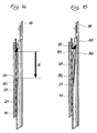
- snap ball 78 of film gripper 76 snaps into snap recess 79 of lens slide 18, and film gripper 76 is carried along (see Fig. 10), its gripper tooth 81 engaging through elongated slot 42 in film cassette 10 and sliding over the perforation of film strip 37.
- film gripper 76 is lifted out of the perforation by a slanted surface 91 configured on film cassette 10 and held in that position by retaining lever 63, as shown by Fig. 15.
- lens carrier 13 mounted in lens slide 18 is brought into its taking position by passing, against the force of return spring 19, over ramp 39 onto support surface 40.
- release button 50 In order to take a photograph, release button 50 is pushed down against the force of return spring 51. This causes release pawl 54 to be pivoted by projection 52 until arm 55 moves away from surface 56 of impact lever 58, and the latter proceeds clockwise as a result of the force of drive spring 57, opens shutter blade 60 against the force of torsion spring 61, and uncovers lens 14 to expose film strip 37.
- cam 62 of impact lever 58 runs against retaining pawl 84 and pivots it, so that firing spring 85 strikes piezo block 86 and fires a flash lamp.
- release pawl 54 also pivots retaining lever 63 via lobe 64, and releases film gripper 76 so that gripper tooth 81 drops into the film perforation (see Fig. 14).
- lens slide 18 In order to prepare for the next picture, lens slide 18 is displaced toward the non-operating position until gripper tooth 81 strikes against stop shoulder 82 in film cassette 10. Film strip 37 is thereby transported one frame interval H. Film gripper 76 remains in snap-locked engagement with lens slide 18. At the same time cam 62 runs against stop 83, and impact lever 58 is rotated once again into its spring-preloaded cocked position in which it is retained by release pawl 54 that is pivoted back. A return element 92 ensures that firing spring 85 is once again held by retaining pawl 84 in the preloaded firing position.
- Retaining lever 63 follows along as release pawl 54 pivots back, so that when lens slide 18 is once again in the taking position, gripper tooth 81 of film gripper 76 is lifted away from the film perforation by means of slanted surface 91. If no picture is taken in this position, but instead lens slide 18 is displaced into the non-operating position, film strip 37 is not transported.
- film gripper 76 is carried along until its gripper tooth 81 contacts stop shoulder 82 and is prevented by it from moving farther.
- the result of this is that the snap-in connection between snap ball 78 of film gripper 76 and snap recess 79 of lens slide 18 is abolished, and the latter, released from film gripper 76, is moved into its non-operating position.
- Lens carrier 13 is returned via ramp 39 into its pulled-in position as shown in Figs. 11 and 12.
- end surface 72 of detent pawl 70 is not located exactly over cutout 73, but rather rests against the end surface of lens slide 18. This makes it impossible to actuate the camera.
Landscapes
- Physics & Mathematics (AREA)
- General Physics & Mathematics (AREA)
- Structure And Mechanism Of Cameras (AREA)
Applications Claiming Priority (2)
| Application Number | Priority Date | Filing Date | Title |
|---|---|---|---|
| DE1996123066 DE19623066A1 (de) | 1996-06-10 | 1996-06-10 | Photographische Kamera |
| DE19623066 | 1996-06-10 |
Publications (2)
| Publication Number | Publication Date |
|---|---|
| EP0813100A2 true EP0813100A2 (fr) | 1997-12-17 |
| EP0813100A3 EP0813100A3 (fr) | 1999-11-10 |
Family
ID=7796504
Family Applications (1)
| Application Number | Title | Priority Date | Filing Date |
|---|---|---|---|
| EP97108993A Withdrawn EP0813100A3 (fr) | 1996-06-10 | 1997-06-04 | Appareil photo et cartouche de film |
Country Status (2)
| Country | Link |
|---|---|
| EP (1) | EP0813100A3 (fr) |
| DE (1) | DE19623066A1 (fr) |
Cited By (1)
| Publication number | Priority date | Publication date | Assignee | Title |
|---|---|---|---|---|
| CN109229695A (zh) * | 2018-08-20 | 2019-01-18 | 浙江吉利控股集团有限公司 | 一种全玻璃磨砂卡盖气味瓶 |
Families Citing this family (29)
| Publication number | Priority date | Publication date | Assignee | Title |
|---|---|---|---|---|
| JPH114371A (ja) | 1997-06-12 | 1999-01-06 | Asahi Optical Co Ltd | デジタルスチルカメラ |
| TWI229231B (en) * | 2002-02-21 | 2005-03-11 | Pentax Corp | Retractable lens system and method of retracting a retractable lens system |
| US6963694B2 (en) | 2002-08-27 | 2005-11-08 | Pentax Corporation | Lens barrel |
| JP2004085934A (ja) | 2002-08-27 | 2004-03-18 | Pentax Corp | ズームレンズ鏡筒の繰出カム機構及び繰出カム機構 |
| US7068929B2 (en) | 2002-08-27 | 2006-06-27 | Pentax Corporation | Optical element retracting mechanism for a retractable lens |
| US7106961B2 (en) | 2002-08-27 | 2006-09-12 | Pentax Corporation | Lens barrel incorporating the advancing/retracting mechanism |
| US7027727B2 (en) | 2002-08-27 | 2006-04-11 | Pentax Corporation | Lens barrel incorporating the cam mechanism |
| US7050713B2 (en) | 2002-08-27 | 2006-05-23 | Pentax Corporation | Optical element retracting mechanism for a photographing lens |
| US6952526B2 (en) | 2002-08-27 | 2005-10-04 | Pentax Corporation | Retractable lens barrel |
| US7031603B2 (en) | 2002-08-27 | 2006-04-18 | Pentax Corporation | Lens barrel |
| US7079761B2 (en) | 2002-08-27 | 2006-07-18 | Pentax Corporation | Optical element retracting mechanism for a photographing lens |
| US6990291B2 (en) | 2002-08-27 | 2006-01-24 | Pentax Corporation | Lens barrel having a moving optical element support frame |
| US7010224B2 (en) | 2002-08-27 | 2006-03-07 | Pentax Corporation | Lens barrel incorporating the rotation transfer mechanism |
| US7031604B2 (en) | 2002-08-27 | 2006-04-18 | Pentax Corporation | Lens barrel incorporating the linear guide mechanism |
| US6965733B1 (en) | 2002-08-27 | 2005-11-15 | Pentax Corporation | Lens barrel incorporating the cam mechanism |
| US7085486B2 (en) | 2002-08-27 | 2006-08-01 | Pentax Corporation | Lens barrel incorporating a rotatable ring |
| US7079762B2 (en) | 2002-08-27 | 2006-07-18 | Pentax Corporation | Supporting structure for supporting a rotatable ring |
| US7035535B2 (en) | 2002-08-27 | 2006-04-25 | Pentax Corporation | Optical element retracting mechanism for a retractable photographing lens |
| US7058293B2 (en) | 2002-08-27 | 2006-06-06 | Pentax Corporation | Optical element retracting mechanism for a retractable lens |
| US6987930B2 (en) | 2002-08-27 | 2006-01-17 | Pentax Corporation | Lens barrel incorporating the advancing/retracting mechanism |
| US7097367B2 (en) | 2002-08-27 | 2006-08-29 | Pentax, Corporation | Optical element retracting mechanism for a photographing lens |
| US7088916B2 (en) | 2002-08-27 | 2006-08-08 | Pentax Corporation | Retractable lens barrel |
| JP3863829B2 (ja) | 2002-08-27 | 2006-12-27 | ペンタックス株式会社 | ズームレンズ鏡筒の繰出カム機構及び繰出カム機構 |
| US6959148B2 (en) | 2002-08-27 | 2005-10-25 | Pentax Corporation | Retractable photographing lens |
| US6978088B2 (en) | 2002-08-27 | 2005-12-20 | Pentax Corporation | Optical element retracting mechanism for a retractable lens |
| JP2004085932A (ja) | 2002-08-27 | 2004-03-18 | Pentax Corp | ズームレンズ鏡筒の繰出カム機構及び繰出カム機構 |
| US7025512B2 (en) | 2002-08-27 | 2006-04-11 | Pentax Corporation | Retracting mechanism of a retractable lens |
| US7229223B2 (en) | 2004-02-03 | 2007-06-12 | Pentax Corporation | Rotation transfer mechanism and a zoom camera incorporating the rotation transfer mechanism |
| JP4520190B2 (ja) | 2004-03-18 | 2010-08-04 | Hoya株式会社 | 沈胴式レンズ鏡筒及び沈胴式レンズ鏡筒を備えたカメラ |
Family Cites Families (9)
| Publication number | Priority date | Publication date | Assignee | Title |
|---|---|---|---|---|
| US3738241A (en) * | 1970-05-18 | 1973-06-12 | G Bahnsen | Camera with film spacer |
| GB1313617A (en) * | 1970-06-10 | 1973-04-18 | Rollei Werke Franke Heidecke | Photographic camera |
| US3950771A (en) * | 1972-03-27 | 1976-04-13 | Agfa-Gevaert, A.G. | Photographic apparatus with expansible housing |
| JPS49131425A (fr) * | 1973-04-23 | 1974-12-17 | ||
| US3987469A (en) * | 1973-08-11 | 1976-10-19 | Agfa-Gevaert, A.G. | Miniature still camera with expansible housing |
| DE2558276A1 (de) * | 1975-12-23 | 1977-07-07 | Agfa Gevaert Ag | Fotografische kamera |
| DE3340695C2 (de) * | 1983-11-10 | 1986-12-18 | Kodak Ag, 7000 Stuttgart | Photographische Kassettenkamera mit einem Zählwerk |
| DE3514648A1 (de) * | 1985-04-23 | 1986-10-23 | Otto Dr. 8000 München Stemme | Fotografische stehbildkamera und filmkassette hierfuer |
| JPH06324388A (ja) * | 1993-05-12 | 1994-11-25 | Canon Inc | カメラ |
-
1996
- 1996-06-10 DE DE1996123066 patent/DE19623066A1/de not_active Withdrawn
-
1997
- 1997-06-04 EP EP97108993A patent/EP0813100A3/fr not_active Withdrawn
Cited By (1)
| Publication number | Priority date | Publication date | Assignee | Title |
|---|---|---|---|---|
| CN109229695A (zh) * | 2018-08-20 | 2019-01-18 | 浙江吉利控股集团有限公司 | 一种全玻璃磨砂卡盖气味瓶 |
Also Published As
| Publication number | Publication date |
|---|---|
| DE19623066A1 (de) | 1997-12-11 |
| EP0813100A3 (fr) | 1999-11-10 |
Similar Documents
| Publication | Publication Date | Title |
|---|---|---|
| EP0813100A2 (fr) | Appareil photo et cartouche de film | |
| US5790907A (en) | Compact photographic camera having lens slide | |
| JP3270227B2 (ja) | 電動巻き上げ装置 | |
| US4068244A (en) | Film advance mechanism | |
| US5555053A (en) | Metering apparatus | |
| EP0017971B1 (fr) | Dispositif de pression, appareil pour vues fixes et cassette de film | |
| US4012754A (en) | Photographic camera | |
| US4746945A (en) | Miniature 110 camera | |
| EP0251171B1 (fr) | Désenclenchment de porte de caméra et verrouillage de rebobinage de film | |
| IE44646B1 (en) | Camera | |
| US4652105A (en) | Frame number counter for disk film camera | |
| US5913084A (en) | One-time-use camera with shutter, flash, and optical film encodement synchronization | |
| EP0813103B1 (fr) | Cassette de film d'un appareil photographique | |
| US6009277A (en) | Imaging apparatus and method of handling film | |
| EP0701163B1 (fr) | Adaptateur pour dos de caméra et procédé associé | |
| US4265527A (en) | Flash unit and camera | |
| US6356711B1 (en) | Lens-fitted photo film unit and sprocket wheel for the same | |
| US5822639A (en) | Camera having self timer unwind without exposure | |
| GB2093203A (en) | Diaphragm and shutter mechanism | |
| JP3723272B2 (ja) | レンズ付きフイルムユニット | |
| JPH0675291A (ja) | フイルムホルダ | |
| JPH0675292A (ja) | フイルムホルダ | |
| JP3835720B2 (ja) | インスタントカメラ | |
| JP4065584B2 (ja) | スプロケット | |
| JPH0675293A (ja) | フイルムホルダ |
Legal Events
| Date | Code | Title | Description |
|---|---|---|---|
| PUAI | Public reference made under article 153(3) epc to a published international application that has entered the european phase |
Free format text: ORIGINAL CODE: 0009012 |
|
| AK | Designated contracting states |
Kind code of ref document: A2 Designated state(s): DE FR GB |
|
| RIC1 | Information provided on ipc code assigned before grant |
Free format text: 6G 03B 17/02 A, 6G 03B 17/26 B, 6G 03B 17/04 B, 6G 03B 17/42 B, 6G 03B 17/32 B, 6G 03B 17/36 B |
|
| PUAL | Search report despatched |
Free format text: ORIGINAL CODE: 0009013 |
|
| AK | Designated contracting states |
Kind code of ref document: A3 Designated state(s): AT BE CH DE DK ES FI FR GB GR IE IT LI LU MC NL PT SE |
|
| 17P | Request for examination filed |
Effective date: 20000419 |
|
| AKX | Designation fees paid |
Free format text: DE FR GB |
|
| 17Q | First examination report despatched |
Effective date: 20030509 |
|
| STAA | Information on the status of an ep patent application or granted ep patent |
Free format text: STATUS: THE APPLICATION IS DEEMED TO BE WITHDRAWN |
|
| 18D | Application deemed to be withdrawn |
Effective date: 20030930 |