EP0813192A1 - Système pour discriminer des disques optiques - Google Patents
Système pour discriminer des disques optiques Download PDFInfo
- Publication number
- EP0813192A1 EP0813192A1 EP97109403A EP97109403A EP0813192A1 EP 0813192 A1 EP0813192 A1 EP 0813192A1 EP 97109403 A EP97109403 A EP 97109403A EP 97109403 A EP97109403 A EP 97109403A EP 0813192 A1 EP0813192 A1 EP 0813192A1
- Authority
- EP
- European Patent Office
- Prior art keywords
- disc
- signal
- focus error
- order spectrum
- focus
- Prior art date
- Legal status (The legal status is an assumption and is not a legal conclusion. Google has not performed a legal analysis and makes no representation as to the accuracy of the status listed.)
- Granted
Links
- 230000003287 optical effect Effects 0.000 title claims abstract description 33
- 238000001228 spectrum Methods 0.000 description 67
- 101100280944 Pisum sativum PETF gene Proteins 0.000 description 6
- 238000010586 diagram Methods 0.000 description 3
- 230000003595 spectral effect Effects 0.000 description 3
- 238000000034 method Methods 0.000 description 2
- 238000007599 discharging Methods 0.000 description 1
- 238000005259 measurement Methods 0.000 description 1
- 238000012544 monitoring process Methods 0.000 description 1
Images



Classifications
-
- G—PHYSICS
- G11—INFORMATION STORAGE
- G11B—INFORMATION STORAGE BASED ON RELATIVE MOVEMENT BETWEEN RECORD CARRIER AND TRANSDUCER
- G11B7/00—Recording or reproducing by optical means, e.g. recording using a thermal beam of optical radiation by modifying optical properties or the physical structure, reproducing using an optical beam at lower power by sensing optical properties; Record carriers therefor
- G11B7/12—Heads, e.g. forming of the optical beam spot or modulation of the optical beam
- G11B7/135—Means for guiding the beam from the source to the record carrier or from the record carrier to the detector
- G11B7/1372—Lenses
-
- G—PHYSICS
- G11—INFORMATION STORAGE
- G11B—INFORMATION STORAGE BASED ON RELATIVE MOVEMENT BETWEEN RECORD CARRIER AND TRANSDUCER
- G11B19/00—Driving, starting, stopping record carriers not specifically of filamentary or web form, or of supports therefor; Control thereof; Control of operating function ; Driving both disc and head
- G11B19/02—Control of operating function, e.g. switching from recording to reproducing
- G11B19/12—Control of operating function, e.g. switching from recording to reproducing by sensing distinguishing features of or on records, e.g. diameter end mark
-
- G—PHYSICS
- G11—INFORMATION STORAGE
- G11B—INFORMATION STORAGE BASED ON RELATIVE MOVEMENT BETWEEN RECORD CARRIER AND TRANSDUCER
- G11B7/00—Recording or reproducing by optical means, e.g. recording using a thermal beam of optical radiation by modifying optical properties or the physical structure, reproducing using an optical beam at lower power by sensing optical properties; Record carriers therefor
- G11B7/002—Recording, reproducing or erasing systems characterised by the shape or form of the carrier
- G11B7/0037—Recording, reproducing or erasing systems characterised by the shape or form of the carrier with discs
-
- G—PHYSICS
- G11—INFORMATION STORAGE
- G11B—INFORMATION STORAGE BASED ON RELATIVE MOVEMENT BETWEEN RECORD CARRIER AND TRANSDUCER
- G11B7/00—Recording or reproducing by optical means, e.g. recording using a thermal beam of optical radiation by modifying optical properties or the physical structure, reproducing using an optical beam at lower power by sensing optical properties; Record carriers therefor
- G11B7/08—Disposition or mounting of heads or light sources relatively to record carriers
- G11B7/085—Disposition or mounting of heads or light sources relatively to record carriers with provision for moving the light beam into, or out of, its operative position or across tracks, otherwise than during the transducing operation, e.g. for adjustment or preliminary positioning or track change or selection
- G11B7/08505—Methods for track change, selection or preliminary positioning by moving the head
- G11B7/08511—Methods for track change, selection or preliminary positioning by moving the head with focus pull-in only
-
- G—PHYSICS
- G11—INFORMATION STORAGE
- G11B—INFORMATION STORAGE BASED ON RELATIVE MOVEMENT BETWEEN RECORD CARRIER AND TRANSDUCER
- G11B7/00—Recording or reproducing by optical means, e.g. recording using a thermal beam of optical radiation by modifying optical properties or the physical structure, reproducing using an optical beam at lower power by sensing optical properties; Record carriers therefor
- G11B7/08—Disposition or mounting of heads or light sources relatively to record carriers
- G11B7/09—Disposition or mounting of heads or light sources relatively to record carriers with provision for moving the light beam or focus plane for the purpose of maintaining alignment of the light beam relative to the record carrier during transducing operation, e.g. to compensate for surface irregularities of the latter or for track following
- G11B7/0908—Disposition or mounting of heads or light sources relatively to record carriers with provision for moving the light beam or focus plane for the purpose of maintaining alignment of the light beam relative to the record carrier during transducing operation, e.g. to compensate for surface irregularities of the latter or for track following for focusing only
Definitions
- the present invention relates to an optical disc discriminating system in an optical disc player for discriminating various kinds of optical discs such as CD and DVD (Digital Video Disc or Digital Versatile Disc).
- CD and DVD Digital Video Disc or Digital Versatile Disc
- a compatible single optical disc player which is capable of reproducing a CD (compact disc) and a LD (laser disc) has been popular. Since the thickness of the CD and the LD from the rear surface to the recording surface is the same (1.2 mm), it is possible to use an optical pickup in which a laser beam is focused on a focal point for reproducing both of the CD and the LD.
- the diameter of the disc is detected for discriminating the CD or the video disc.
- the DVD having a high recording density has been developed.
- the thickness of the CD from the surface to the recording surface is 1.2 mm
- the thickness of the DVD is about 0.6 mm.
- the principle of a reading system of recording pits of the DVD is the same as that of the CD. Therefore, a compatible single optical disc player which is capable of reproducing the CD and the DVD has greatly been proposed.
- a compatible CD/DVD player in order to properly focus the beam for reading the information on the recording surface of the disc, two types of lenses are provided, each having a focal length suitable for a thickness of a corresponding disc.
- a double focus lens using a hologram element is provided as another type of the compatible CD/DVD player.
- Fig. 8a shows an optical pickup having a double focus lens using a hologram element (diffraction grating).
- the double focus lens comprises a diffraction grating 13, an objective lens 11 disposed on the same optical path, and a collimator lens 14.
- a beam of light is paralleled by the collimator lens 14 and divided into three spectral beams of 0 order spectrum (having a 90 diffraction angle) and ⁇ 1 order spectrum by the diffraction grating 13 (-1 order spectrum is not shown). Since focal lengths of the 0 order spectrum and the +1 order spectrum are different from each other, each of the 0 order spectrum (hereinafter called zero-order spectrum) and the +1 order spectrum (hereinafter called first-order spectrum) is focused on a different position of the same line.
- the zero-order spectrum is properly focused on the recording surface of the DVD, while the first-order spectrum is properly focused on the recording surface of the CD.
- the recording surface is irradiated with the zero-order spectrum first.
- a four-divided photodetector provided in the pickup (not shown) produces an S-shaped signal as a focus error signal.
- the pickup is further moved away, the first-order spectrum reflected from the disc passes an optical path of the zero-order spectrum, thereby forming a pseudo spectrum.
- a pseudo S-shaped signal of the pseudo spectrum is produced.
- an S-shaped signal of the first-order spectrum is produced as a focus error signal.
- Fig. 8b shows S shaped signals of the corresponding zero-order spectrum, pseudo spectrum, and first-order spectrum with respect to the movements of the double focus lens of Fig. 8a.
- the spectral ratio of the zero -order spectrum and the first-order spectrum is set to 1:1.
- the zero-order spectrum achieves the optimum focus on the DVD, while the first-order spectrum achieves the optimum focus on the CD. If the amount of the S-shaped signal by the zero-order spectrum on the DVD is 100%, the amount of the signal corresponding to the CD is small, less than 100%. Similarly, if the amount of the S-shaped signal by the first-order spectrum on the CD is 100%, the amount of the signal corresponding to the DVD is small, less than 100%. Thus, in the double focus lens, the amplitudes of the respective focus error signals are different from each other.
- the ratio of zero-order spectrum to first -order spectrum of the DVD, namely zero-order spectrum / first-order spectrum is larger than the ratio of zero -order spectrum to first-order spectrum of the CD, that is zero-order spectrum / first-order spectrum.
- a focus servo control system is provided for each disc.
- the pickup is vertically moved against the disc, and a focus error (FE) signal is produced for detecting a proper focal point for focusing in.
- FE focus error
- a plurality of focus error signals S-shaped signals by zero-order spectrum, pseudo spectrum and first-order spectrum
- S-shaped signals by zero-order spectrum, pseudo spectrum and first-order spectrum are obtained. Accordingly, a problem that focusing in is achieved by an S-shaped signal detected first arises. In other words, there may be occur an erroneous focusing by an improper spectrum.
- An object of the present invention is to provide an optical disc discriminating system for an optical disc player which may properly discriminate a CD and a DVD, and select an optimum S-shaped signal in a focus error signal for focusing in.
- a system for discriminating various kinds of optical discs which are different in thickness comprising focusing means for focusing a laser beam at positions on an optical axis of the optical pickup, the number of the positions being corresponded to the number of kinds of the discs, moving means for moving the focusing means along the optical axis, photodetector means for receiving a laser beam reflected from the disc and for producing a focus error signal, detector means for detecting the difference between the focus error signals, caused by the difference in thickness of the discs and the difference in focal point of the laser beam, and for discriminating the kind of the disc.
- the focusing means comprises a diffraction grating and an objective lens.
- the detector means detects the difference in level of the focus error signal.
- the detector means detects the difference in timing of production of the focus error signal.
- the detector means detects the difference in position of the focusing means when the focus error signal is produced.
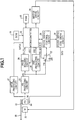
- an optical disc 20 to be reproduced is mounted on the player and rotated by a spindle motor 21.
- An optical pickup 22 has a double focus lens which has the same principle as Fig. 8a. The pickup 22 emits a laser beam, and pits formed on a recording surface of the disc 20 is irradiated with the beam for reading information recorded with the pits.
- An output signal of the pickup 22 is fed to a focus error (FE) producing circuit 23.
- the FE producing circuit 23 produces a focus error signal.
- the focus error signal is applied to a peak holding circuit 24.
- the peak holding circuit 24 holds the maximum amplitude voltage of the positive pole side of the focus error signal as a peak voltage at a substantially constant value.
- the peak holding circuit 24 applies the peak voltage to a microcomputer 25.
- the microcomputer 25 produces a reset (RST) signal which is applied to the peak holding circuit 24 for resetting the maximum voltage held in the circuit.
- RST reset
- a maximum amplitude voltage of the positive pole side of the next focus error signal is held as the maximum voltage.
- the output signal from the pickup 22 is further applied to an RFOK producing circuit 37.
- the RFOK producing circuit 37 receives an added signal of a four-divided photodetector. When the added focus signal exceeds a predetermined threshold value, the RFOK producing circuit 37 produces an RFOK signal which is applied to the microcomputer 25. Namely, the production of the RFOK signal means the laser beam is located at a position near focused position.
- the focus error signal from the FE producing circuit 23 is further applied to a focus zero cross (FZC) producing circuit 26.
- the FZC producing circuit 26 is a zero cross comparator comprising an operational amplifier and produces a focus zero cross detecting signal in the form of pulses. The production of the FZC signal means that the spectrum is focused.
- the FZC signal is applied to the microcomputer 25.
- the focus error signal from the FE producing circuit 23 is also applied to a fixed contact of a loop switch 27.
- the loop switch 27 is operated by an FE shunt signal from the microcomputer 25.
- a movable contact of the loop switch 27 is connected to a focus servo control circuit 28 which is connected to the microcomputer 25.
- the focus servo control circuit 28 is further connected to a focus servo coil drive circuit 29 which is connected to an actuator coil 30.
- a focus servo loop comprising the FE producing circuit 23, microcomputer 25, focus servo control circuit 28, focus servo coil drive circuit 29 and actuator coil 30 is closed.
- the focus error signal is applied to the focus servo controller 28 for automatically controlling the focus servo.
- the microcomputer 25 When the loop switch 27 is opened (OFF-state), the microcomputer 25 operates the focus servo coil drive circuit 29 to produce the drive voltage for driving the actuator coil 30. Thus, the lens in the pickup is moved downward and upward at a predetermined speed for discriminating the disc.
- the microcomputer 25 is further connected to a RAM 32, a ROM 33 and a motor drive circuit 31.
- the RAM 32 stores data of signals (time and voltage) detected by circuits, and set values obtained by the detected signals.
- the ROM 33 stores data of set values necessary for the system.
- the motor drive circuit 31 produces a drive signal for driving the spindle motor 21.
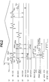
- Figs. 2a to 2g show time charts of signals for explaining the operation of the system.
- the double focus lens in the pickup 22 has the same principle as Fig. 8a, and the spectral ratio of the zero-order spectrum and the first-order spectrum is 1:1.
- the relationship between the maximum amplitudes of the S-shaped signals of zero-order spectrum and first -order spectrum is represented as follows. (FED0/FED1)>(FEC0/FEC1) where
- Fig. 2a shows a focus drive voltage SFD for representing a position voltage of the lens.
- a mark UH is the highest position of the lens (the closest position of the lens to the optical disc 20), and a mark UL is the lowest position of the lens (the farthest position of the lens from the disc).
- Figs. 2b and 2c show voltages of the focus error signals (FE) having S shape for the CD and the DVD, respectively, obtained during the upward and downward movements of the lens.
- a mark TH1 is a threshold of the voltage stored in the ROM 33 for detecting the S-shaped signal.
- the TH1 is set at least smaller than the maximum amplitude voltages obtained by the zero-order spectrum of the CD and DVD.
- the FZC signal is produced by comparing with the TH1.
- a mark TH2 is a threshold set to a value between the maximum amplitude voltage of the S-shaped signal of the CD by the first-order spectrum FEC1 and the maximum amplitude voltage of the S-shaped signal of the DVD by the first-order spectrum FED1 (FEC1>TH2>FED1).
- the TH2 is stored in the ROM 33 or obtained by multiplying the S-shaped signal by the zero-order spectrum and a coefficient together. In this state, influence of the reflectance of the disc is prevented.
- Fig. 2d shows the zero cross detecting pulse signal FZC for each of CD and DVD obtained by the FZC producing circuit 26 when the zero cross of the S-shaped signal is detected.
- Fig. 2e shows the reset pulse signal RST for each of CD and DVD applied from the microcomputer 25.
- Fig. 2f shows output signals of the peak voltages from the peak holding circuit 24 for CD and DVD.
- a mark V1 is a waveform and a measured point of the maximum amplitude voltage of the S-shaped signal by the zero-order spectrum.
- a mark V2 is a waveform and a measured point of the maximum amplitude voltage of the S-shaped signal by the first-order spectrum.
- marks T1 and T2 are times measured by a timer provided in the microcomputer 25.
- the time T1 represents the time when the peak voltage is reset after the peak voltage of the zero-order spectrum is measured by the FZC formed by the S-shaped signal of the zero-order spectrum.
- the pseudo S-shaped signal is large, and if the time is set to the middle between the pseudo spectrum and the first-order spectrum after the peak voltage is measured to pass the pseudo S-shaped signal, the pseudo S-shaped signal is masked.
- the time T2 represents the time passing the first-order spectrum from the FZC and measuring the peak voltage of first -order spectrum, or the time until the lens reaches the lowest position UL.
- Fig. 2g shows the RFOK signal of each of CD and DVD, which will be described hereinafter.
- the optical disc 20 is loaded on the disc player.
- the loop switch 27 is opened (OFF-state), and the double focus lens in the pickup 22 is moved up to the highest position UH.
- the peak voltage is reset, and the lens is moved down from the highest position UH to the lowest position UL at a predetermined set speed. During the downward movement of the lens, the pickup 22 produces the focus error signal.
- the maximum voltage of the FE of the S-shaped signal is monitored by the FZC signal if the FE exceeds the threshold TH1.
- the timer is set at a step S5.
- the peak voltage of the positive pole side of the S-shaped signal obtained first by the peak holding circuit 24 for a predetermined time is stored in the RAM 32 as the peak voltage V1.
- a time T measured by the timer is compared with the set time T1 stored in the ROM 33. If T ⁇ T1, the microcomputer 25 applies the reset signal RST to the peak holding circuit 24 for discharging the peak voltage V1 held therein to be zero at a step S8. If not at the step S7, the timer is set until T ⁇ T1 is obtained.
- the measured time T is compared with the set time T2 stored in the ROM 33. If T ⁇ T2, when the timer counts the time T2 at a step S10, the peak voltage held in the peak holding circuit 24 is stored in the RAM 32 as the peak voltage V2.
- the peak voltage V2 is compared with the threshold TH2 stored in the ROM 33. If V2 ⁇ TH2, it is determined that the disc 20 is CD at a step S13. If not, it is determined that the disc 20 is DVD at a step S12.
- the position of the lens is monitored until SFD ⁇ UL.
- the timer is reset at a step S15.
- the lens is moved up.
- the position of the lens is monitored until SFD ⁇ UH.
- the lens is moved down at a step S18.
- the S-shaped signal obtained first is monitored by the FZC until the FE exceeds the threshold TH1.
- FE ⁇ TH1 and when it is determined that the disc determined at the step 11 is CD at a step S20, the timer is set at a step S21. If the disc is DVD at the step S20, the program goes to a step S23.
- the measured time T is monitored until T ⁇ T1.
- the microcomputer 25 is operated to close the loop switch 27 at the step S23.
- the zero cross signal FZC is produced, it is determined that the laser beam is focused.
- a series operation for disc discrimination is terminated.
- step S11 although the disc is discriminated by V2 ⁇ TH2, there is another method for discriminating the disc.
- the disc since (FEC0/FEC1) ⁇ (FED0/FED1), the disc may be discriminated by the peak voltages V1 and V2 of the peak holding circuit 24. If a certain value ⁇ is set to (FEC0/FEC1) ⁇ (FED0/FED1), and the disc is discriminated with the value ⁇ , the disc can be discriminated without influenced by the reflectance of the disc.
- Fig. 2g shows the RFOK signal of each of CD and DVD.
- timings for starting the measurement of times T1 and T2 may be determined by the RFOK signals, not the FZC of the zero-order spectrum. Furthermore, it is possible to determine the timings when the peak voltage output exceeds the TH1.
- the lens may be moved from the lowest position to the highest position.
- the S -shaped signal becomes the order of first-order spectrum, pseudo spectrum and zero-order spectrum, it is possible to discriminate the disc in the same manner.
- the timing for resetting the focus is set to the middle between the pseudo S-shaped signal and the S-shaped signal by the first-order spectrum, it is possible to reset after the V1 is measured if the pseudo S-shaped signal is small.
- the disc may be rotated at a predetermined speed at the step S2.
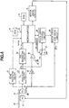
- Fig. 4 shows a system employed for second and third embodiments.
- an equalizer (EQ) 34 for correcting the drive voltage applied to the actuator coil 30, and a comparator 36 having a reference voltage source 35 as a reference voltage for detecting voltage are provided, and the peak holding circuit 24 of the first embodiment is omitted.
- Other structures are the same as those of the first embodiment, and the same parts are identified with the reference numerals as Fig. 1, and the descriptions thereof are omitted.
- the EQ 34 is operated for linearly holding a relationship between the drive voltage of the actuator coil 30 and the position of the lens.
- An output voltage of the EQ 34 is applied to an input terminal of the comparator 36 and the other input terminal is connected to the reference voltage source 35.
- FIGs. 5a and 5b show signals for operating the system for second and third embodiments.
- a mark FD is a focus drive voltage of the drive voltage of the actuator coil 30 converted by the EQ 34.
- the FD is linearly changed with respect to the position voltage SFD.
- a mark TD1 is a detecting time of the DVD and a mark TC1 is a detecting time of the CD.
- the detecting times TD1 and TC1 are stored in the ROM 33 as set values.
- the FD produced at the detecting time TD1 or TC1 is stored in the ROM 33 as a set value.
- Marks E1 and E2 are voltages thereof.
- the disc 20 is loaded on the disc player.
- the lens is moved up to the highest position UH.
- the lens is moved down from the highest position UH to the lowest position UL at a predetermined set speed.
- the FD is monitored, and when FD ⁇ E, the timer is set at a step S5.
- an S -shaped signal detected first is monitored by the FZC.
- the timer is stopped at a step S7.
- the time during the timer is set is stored in the RAM 32.
- the time T is compared to the set time TD1 stored in the ROM 33. The time T is set to TC1 ⁇ T ⁇ TD1. If T ⁇ TD1, it is determined that the disc is DVD at a step S10. If not, it is determined that the disc is CD at a step S11.
- the disc 20 is loaded on the disc player.
- the lens is moved up to the highest position UH.
- the lens is moved down from the highest position UH to the lowest position UL at a predetermined set speed.
- the S -shaped signal obtained first is monitored by the FZC until the FE exceeds the threshold TH1.
- the FD is stored in the RAM 32 at a step S5.
- the FD (E1 or E2) stored in the RAM 32 is compared with a reference voltage E0 stored in the ROM 33.
- the reference voltage E0 is set to the value to meet E1 ⁇ E0 ⁇ E2.
- the FZC of the zero-order spectrum for monitoring the programs may be effective by the RFOK signal shown in Fig. 2g of the first embodiment, or by the peak voltage output exceeds the TH1.
- the lens may be moved from the lowest position to the highest position.
- the EQ 34 is provided for removing noises of the high frequency range of the focus drive signal. If there is no noises, the EQ 34 may be omitted.
- the disc may be rotated at a predetermined speed at the step S2.
- the objective lens for focusing the beam on the disc is moved from the predetermined position, thereby obtain the focus error signal.
- the time is measured.
- the level of the focus error signal at the predetermined time is compared with a set reference level.
- the focus drive voltage is detected.
- the detected focus drive voltage is compared with the reference voltage and the time for detecting the voltage is compared with a reference time.
Landscapes
- Physics & Mathematics (AREA)
- Optics & Photonics (AREA)
- Optical Recording Or Reproduction (AREA)
- Moving Of The Head For Recording And Reproducing By Optical Means (AREA)
Applications Claiming Priority (3)
| Application Number | Priority Date | Filing Date | Title |
|---|---|---|---|
| JP17189096A JP3439300B2 (ja) | 1996-06-11 | 1996-06-11 | 情報記録媒体判別装置 |
| JP171890/96 | 1996-06-11 | ||
| JP17189096 | 1996-06-11 |
Publications (2)
| Publication Number | Publication Date |
|---|---|
| EP0813192A1 true EP0813192A1 (fr) | 1997-12-17 |
| EP0813192B1 EP0813192B1 (fr) | 2003-09-03 |
Family
ID=15931710
Family Applications (1)
| Application Number | Title | Priority Date | Filing Date |
|---|---|---|---|
| EP97109403A Expired - Lifetime EP0813192B1 (fr) | 1996-06-11 | 1997-06-10 | Procédé pour discriminer des disques optiques |
Country Status (5)
| Country | Link |
|---|---|
| US (2) | US6327234B1 (fr) |
| EP (1) | EP0813192B1 (fr) |
| JP (1) | JP3439300B2 (fr) |
| CN (1) | CN1110035C (fr) |
| DE (1) | DE69724520T2 (fr) |
Cited By (13)
| Publication number | Priority date | Publication date | Assignee | Title |
|---|---|---|---|---|
| EP0856839A1 (fr) * | 1997-01-29 | 1998-08-05 | Alpine Electronics, Inc. | Lecteur de support d'enregistrement optique |
| EP0903735A4 (fr) * | 1997-01-10 | 2000-01-05 | Sony Corp | Systeme de disques optiques et systeme discernant les disques optiques |
| EP0987704A1 (fr) * | 1998-09-18 | 2000-03-22 | Mitsumi Electric Company Ltd. | Unité de disques optiques et méthode de discrimination de différents types de disques optiques |
| US6252834B1 (en) | 1997-01-10 | 2001-06-26 | Sony Corporation | Optical disc device and optical disc discriminating method |
| EP1408488A3 (fr) * | 2002-10-07 | 2004-12-08 | Samsung Electronics Co., Ltd. | Procédé et appareil de focalisation adaptatif |
| EP1434216A3 (fr) * | 2002-12-18 | 2006-05-31 | Hitachi-LG Data Storage Korea Inc. | Méthode et appareil pour la discrimination des différents types de disques optiques multicouches |
| EP1646040A3 (fr) * | 1996-03-12 | 2006-12-06 | Deutsche Thomson-Brandt Gmbh | Appareil de lecture et/ou d'écriture sur des supports d'enregistrement optiques de constructions diverses |
| US7570561B2 (en) | 2004-05-25 | 2009-08-04 | Bryan Tai | Method for determining type of digital versatile discs |
| US7602684B2 (en) | 2003-09-15 | 2009-10-13 | Chun-Ta Chen | Discriminating method of an optical disc device for ascertaining the format of a loaded optical disc |
| US7626907B2 (en) | 2004-05-25 | 2009-12-01 | Ricky Chang | Method and apparatus for determining type of digital versatile disc |
| US7746745B2 (en) | 2004-05-25 | 2010-06-29 | Ricky Chang | Method for determining the type of digital versatile disc |
| US7843786B2 (en) | 2002-10-24 | 2010-11-30 | Yi-Chung Chan | Discrimination method of optical storage medium |
| US7995434B2 (en) | 2003-10-31 | 2011-08-09 | Tian Holdings, Llc | Method and apparatus for generating absolute time in pregroove data |
Families Citing this family (15)
| Publication number | Priority date | Publication date | Assignee | Title |
|---|---|---|---|---|
| JP3780661B2 (ja) * | 1997-10-17 | 2006-05-31 | ソニー株式会社 | フォーカスサーチ方法及びフォーカスサーチ装置 |
| JP3367444B2 (ja) * | 1999-02-18 | 2003-01-14 | 船井電機株式会社 | 光ディスクの記録再生装置に適用される光ピックアップ装置 |
| KR100606665B1 (ko) * | 1999-04-19 | 2006-07-31 | 엘지전자 주식회사 | 광 기록매체의 종류 판별 방법 및 장치 |
| KR100606669B1 (ko) * | 1999-05-19 | 2006-07-31 | 엘지전자 주식회사 | 광 기록매체의 기록재생 방법 |
| JP4226184B2 (ja) * | 2000-02-28 | 2009-02-18 | パイオニア株式会社 | 情報記録媒体判別装置及び情報記録媒体判別方法 |
| JP2002260246A (ja) * | 2001-03-02 | 2002-09-13 | Texas Instr Japan Ltd | 光ディスク判別回路 |
| TWI227024B (en) * | 2002-11-08 | 2005-01-21 | Lite On It Corp | Method for increasing focus recovery stability of compact disk drive |
| TWI229855B (en) * | 2002-11-29 | 2005-03-21 | Lite On It Corp | Determination method of optical medium |
| US20060181972A1 (en) * | 2003-04-02 | 2006-08-17 | Yak Aik S | Disc drive apparatus, and method for recognizing cd and dvd |
| TWI238382B (en) * | 2003-09-04 | 2005-08-21 | Lite On It Corp | A disk discrimination method |
| US7675824B2 (en) * | 2005-07-19 | 2010-03-09 | Sony Computer Entertainment Inc. | Optical disc apparatus |
| JP4583328B2 (ja) * | 2006-02-28 | 2010-11-17 | パナソニック株式会社 | 光ディスク装置および光ディスク判別方法 |
| KR101279030B1 (ko) * | 2006-06-30 | 2013-07-05 | 삼성전자주식회사 | 광디스크 장치 및 그의 포커싱 방법 |
| JP4272222B2 (ja) * | 2006-07-28 | 2009-06-03 | 株式会社ソニー・コンピュータエンタテインメント | 光ディスク装置、その制御方法、及びプログラム |
| JP2008123570A (ja) * | 2006-11-08 | 2008-05-29 | Sony Corp | 光記録媒体駆動装置及び光記録媒体駆動方法 |
Citations (10)
| Publication number | Priority date | Publication date | Assignee | Title |
|---|---|---|---|---|
| JPH0554406A (ja) * | 1991-08-21 | 1993-03-05 | Matsushita Electric Ind Co Ltd | 光デイスク装置 |
| EP0610055A2 (fr) * | 1993-02-01 | 1994-08-10 | Matsushita Electric Industrial Co., Ltd. | Lentille d'objectif composé avec deux foyers, et dispositif utilisant cette lentille |
| JPH06333255A (ja) * | 1993-05-25 | 1994-12-02 | Matsushita Electric Ind Co Ltd | 光ヘッド装置 |
| DE19535112A1 (de) * | 1994-09-27 | 1996-03-28 | Nippon Columbia | Kompatibles Laserplattensystem für Laserplatten unterschiedlicher Aufzeichnungsdichte |
| JPH08249801A (ja) * | 1995-03-10 | 1996-09-27 | Pioneer Electron Corp | 反射型光ディスクプレーヤにおけるディスク判別方法 |
| JPH08306056A (ja) * | 1995-05-08 | 1996-11-22 | Sanyo Electric Co Ltd | 光記録媒体のディスク厚判別装置 |
| GB2304226A (en) * | 1995-08-07 | 1997-03-12 | Samsung Electronics Co Ltd | Method for discriminating between different types of optical disk |
| EP0767455A2 (fr) * | 1995-10-06 | 1997-04-09 | Pioneer Electronic Corporation | Méthode et appareil pour le jugement d'un milieu d'enregistrement optique, et méthode et appareil de commande d'asservissement de focalisation |
| GB2309816A (en) * | 1996-01-29 | 1997-08-06 | Samsung Electronics Co Ltd | Automatic discrimination between different kinds of optical disk |
| GB2310311A (en) * | 1996-02-14 | 1997-08-20 | Samsung Electronics Co Ltd | Discriminating between discs having different thicknesses |
Family Cites Families (8)
| Publication number | Priority date | Publication date | Assignee | Title |
|---|---|---|---|---|
| JPS63153456A (ja) | 1986-12-18 | 1988-06-25 | Yokogawa Electric Corp | 光デイスクテストシステム |
| US5511050A (en) | 1988-09-21 | 1996-04-23 | Hitachi, Ltd. | Focus error detecting method and optical head using the same |
| JPH06333225A (ja) | 1993-05-19 | 1994-12-02 | Matsushita Electric Ind Co Ltd | 薄膜磁気記録媒体 |
| JP3413684B2 (ja) | 1994-12-16 | 2003-06-03 | ソニー株式会社 | 多層光ディスク再生装置および方法 |
| KR100234257B1 (ko) * | 1995-08-30 | 1999-12-15 | 윤종용 | 대물렌즈 장치 및 안정된 포커스 서보 신호를 얻는방법 및 이를 적용한 광픽업 장치 및 두께가 다른 디스크를 판별하는 방법 및 두께가 다른 디스크로부터 정보를 재생하고 기록하는 방법 |
| JPH09102129A (ja) * | 1995-10-05 | 1997-04-15 | Pioneer Electron Corp | フォーカスサーボ制御方法及び装置 |
| US6240054B1 (en) * | 1996-05-15 | 2001-05-29 | Pioneer Electronic Corporation | Multiple layer disk reproducing apparatus, and apparatus for reproducing information record medium |
| TW385435B (en) * | 1996-05-30 | 2000-03-21 | Hitachi Ltd | An optical disk discriminating system of optical disk apparatus |
-
1996
- 1996-06-11 JP JP17189096A patent/JP3439300B2/ja not_active Expired - Fee Related
-
1997
- 1997-06-10 DE DE69724520T patent/DE69724520T2/de not_active Expired - Lifetime
- 1997-06-10 EP EP97109403A patent/EP0813192B1/fr not_active Expired - Lifetime
- 1997-06-11 CN CN97112739.5A patent/CN1110035C/zh not_active Expired - Fee Related
-
2000
- 2000-06-19 US US09/597,539 patent/US6327234B1/en not_active Expired - Fee Related
-
2001
- 2001-11-13 US US09/987,011 patent/US6487153B2/en not_active Expired - Fee Related
Patent Citations (10)
| Publication number | Priority date | Publication date | Assignee | Title |
|---|---|---|---|---|
| JPH0554406A (ja) * | 1991-08-21 | 1993-03-05 | Matsushita Electric Ind Co Ltd | 光デイスク装置 |
| EP0610055A2 (fr) * | 1993-02-01 | 1994-08-10 | Matsushita Electric Industrial Co., Ltd. | Lentille d'objectif composé avec deux foyers, et dispositif utilisant cette lentille |
| JPH06333255A (ja) * | 1993-05-25 | 1994-12-02 | Matsushita Electric Ind Co Ltd | 光ヘッド装置 |
| DE19535112A1 (de) * | 1994-09-27 | 1996-03-28 | Nippon Columbia | Kompatibles Laserplattensystem für Laserplatten unterschiedlicher Aufzeichnungsdichte |
| JPH08249801A (ja) * | 1995-03-10 | 1996-09-27 | Pioneer Electron Corp | 反射型光ディスクプレーヤにおけるディスク判別方法 |
| JPH08306056A (ja) * | 1995-05-08 | 1996-11-22 | Sanyo Electric Co Ltd | 光記録媒体のディスク厚判別装置 |
| GB2304226A (en) * | 1995-08-07 | 1997-03-12 | Samsung Electronics Co Ltd | Method for discriminating between different types of optical disk |
| EP0767455A2 (fr) * | 1995-10-06 | 1997-04-09 | Pioneer Electronic Corporation | Méthode et appareil pour le jugement d'un milieu d'enregistrement optique, et méthode et appareil de commande d'asservissement de focalisation |
| GB2309816A (en) * | 1996-01-29 | 1997-08-06 | Samsung Electronics Co Ltd | Automatic discrimination between different kinds of optical disk |
| GB2310311A (en) * | 1996-02-14 | 1997-08-20 | Samsung Electronics Co Ltd | Discriminating between discs having different thicknesses |
Non-Patent Citations (4)
| Title |
|---|
| PATENT ABSTRACTS OF JAPAN vol. 017, no. 366 (P - 1571) 9 July 1993 (1993-07-09) * |
| PATENT ABSTRACTS OF JAPAN vol. 095, no. 003 28 April 1995 (1995-04-28) * |
| PATENT ABSTRACTS OF JAPAN vol. 097, no. 001 31 January 1997 (1997-01-31) * |
| PATENT ABSTRACTS OF JAPAN vol. 097, no. 003 31 March 1997 (1997-03-31) * |
Cited By (16)
| Publication number | Priority date | Publication date | Assignee | Title |
|---|---|---|---|---|
| EP1646040A3 (fr) * | 1996-03-12 | 2006-12-06 | Deutsche Thomson-Brandt Gmbh | Appareil de lecture et/ou d'écriture sur des supports d'enregistrement optiques de constructions diverses |
| US6252834B1 (en) | 1997-01-10 | 2001-06-26 | Sony Corporation | Optical disc device and optical disc discriminating method |
| EP0903735A4 (fr) * | 1997-01-10 | 2000-01-05 | Sony Corp | Systeme de disques optiques et systeme discernant les disques optiques |
| US6229772B1 (en) | 1997-01-10 | 2001-05-08 | Sony Corporation | Optical disc device and optical disc discriminating method |
| EP0856839A1 (fr) * | 1997-01-29 | 1998-08-05 | Alpine Electronics, Inc. | Lecteur de support d'enregistrement optique |
| US6760289B1 (en) | 1998-09-18 | 2004-07-06 | Koji Ide | Optical disc drive and method of discriminating various types of optical discs |
| EP0987704A1 (fr) * | 1998-09-18 | 2000-03-22 | Mitsumi Electric Company Ltd. | Unité de disques optiques et méthode de discrimination de différents types de disques optiques |
| EP1408488A3 (fr) * | 2002-10-07 | 2004-12-08 | Samsung Electronics Co., Ltd. | Procédé et appareil de focalisation adaptatif |
| US7184373B2 (en) | 2002-10-07 | 2007-02-27 | Samsung Electronics Co., Ltd. | Adaptive focusing method and apparatus |
| US7843786B2 (en) | 2002-10-24 | 2010-11-30 | Yi-Chung Chan | Discrimination method of optical storage medium |
| EP1434216A3 (fr) * | 2002-12-18 | 2006-05-31 | Hitachi-LG Data Storage Korea Inc. | Méthode et appareil pour la discrimination des différents types de disques optiques multicouches |
| US7602684B2 (en) | 2003-09-15 | 2009-10-13 | Chun-Ta Chen | Discriminating method of an optical disc device for ascertaining the format of a loaded optical disc |
| US7995434B2 (en) | 2003-10-31 | 2011-08-09 | Tian Holdings, Llc | Method and apparatus for generating absolute time in pregroove data |
| US7570561B2 (en) | 2004-05-25 | 2009-08-04 | Bryan Tai | Method for determining type of digital versatile discs |
| US7626907B2 (en) | 2004-05-25 | 2009-12-01 | Ricky Chang | Method and apparatus for determining type of digital versatile disc |
| US7746745B2 (en) | 2004-05-25 | 2010-06-29 | Ricky Chang | Method for determining the type of digital versatile disc |
Also Published As
| Publication number | Publication date |
|---|---|
| DE69724520T2 (de) | 2004-06-24 |
| DE69724520D1 (de) | 2003-10-09 |
| CN1110035C (zh) | 2003-05-28 |
| JPH09330553A (ja) | 1997-12-22 |
| JP3439300B2 (ja) | 2003-08-25 |
| US20020031072A1 (en) | 2002-03-14 |
| CN1177797A (zh) | 1998-04-01 |
| US6327234B1 (en) | 2001-12-04 |
| EP0813192B1 (fr) | 2003-09-03 |
| US6487153B2 (en) | 2002-11-26 |
Similar Documents
| Publication | Publication Date | Title |
|---|---|---|
| EP0813192B1 (fr) | Procédé pour discriminer des disques optiques | |
| US6240054B1 (en) | Multiple layer disk reproducing apparatus, and apparatus for reproducing information record medium | |
| EP0767456B1 (fr) | Méthode et appareil de commande d'asservissement de focalisation | |
| US5790493A (en) | Optical record medium judging method and apparatus and focus servo controlling method and apparatus | |
| KR100197623B1 (ko) | 디스크종류판별방법 및 이를 적용한 dvd시스템 | |
| US5724325A (en) | Method for reducing lead in time in an optical disk recording or reproducing apparatus capable of processing data for multiple types of disks | |
| US20010055256A1 (en) | Disk type determining apparatus, optical disk reproducing apparatus and tracking error signal generating apparatus | |
| KR20000066576A (ko) | 광 기록매체의 종류 판별 방법 | |
| JP3553241B2 (ja) | 光ディスク装置 | |
| US7050366B2 (en) | Device and method for detecting non-writable region of optical recording medium | |
| EP1049086A1 (fr) | Appareil et méthode de commande de la vitesse de reproduction d'un disque optique | |
| JP4093233B2 (ja) | 光ディスク装置及びこれに用いる収差補正方法 | |
| US5966355A (en) | Focus servo pull-in apparatus for use in a compatible disk player | |
| KR100464413B1 (ko) | 광기록매체의 종류 판별방법 및 장치 | |
| KR100533747B1 (ko) | 광디스크 종류 판별방법 | |
| EP1614109B1 (fr) | Appareil lecteur de disque, et procede pour reconnaitre un cd et un dvd | |
| US20050052978A1 (en) | Method of discriminating optical disc type and apparatus thereof | |
| JP2882383B2 (ja) | 光ディスク記録再生装置 | |
| JPH09320179A (ja) | 光学式記録媒体判別方法及び光学式記録媒体読取装置 | |
| KR100319552B1 (ko) | 광 디스크 유형 판별방법 | |
| KR100506826B1 (ko) | 광 디스크 유형 판별방법 | |
| KR100587266B1 (ko) | 광 기록매체의 기록재생 방법 | |
| JP2003157544A (ja) | 情報記録媒体判別装置 | |
| JPH09320073A (ja) | 再生装置 | |
| KR970002925A (ko) | 광디스크의 기록밀도판별장치 |
Legal Events
| Date | Code | Title | Description |
|---|---|---|---|
| PUAI | Public reference made under article 153(3) epc to a published international application that has entered the european phase |
Free format text: ORIGINAL CODE: 0009012 |
|
| AK | Designated contracting states |
Kind code of ref document: A1 Designated state(s): DE FR GB |
|
| 17P | Request for examination filed |
Effective date: 19971201 |
|
| AKX | Designation fees paid |
Free format text: DE FR GB |
|
| RBV | Designated contracting states (corrected) |
Designated state(s): DE FR GB |
|
| 17Q | First examination report despatched |
Effective date: 20010504 |
|
| RTI1 | Title (correction) |
Free format text: METHOD FOR DISCRIMINATING OPTICAL DISCS |
|
| GRAH | Despatch of communication of intention to grant a patent |
Free format text: ORIGINAL CODE: EPIDOS IGRA |
|
| GRAS | Grant fee paid |
Free format text: ORIGINAL CODE: EPIDOSNIGR3 |
|
| GRAA | (expected) grant |
Free format text: ORIGINAL CODE: 0009210 |
|
| AK | Designated contracting states |
Kind code of ref document: B1 Designated state(s): DE FR GB |
|
| REG | Reference to a national code |
Ref country code: GB Ref legal event code: FG4D |
|
| REF | Corresponds to: |
Ref document number: 69724520 Country of ref document: DE Date of ref document: 20031009 Kind code of ref document: P |
|
| REG | Reference to a national code |
Ref country code: GB Ref legal event code: 746 Effective date: 20040506 |
|
| ET | Fr: translation filed | ||
| PLBE | No opposition filed within time limit |
Free format text: ORIGINAL CODE: 0009261 |
|
| STAA | Information on the status of an ep patent application or granted ep patent |
Free format text: STATUS: NO OPPOSITION FILED WITHIN TIME LIMIT |
|
| 26N | No opposition filed |
Effective date: 20040604 |
|
| REG | Reference to a national code |
Ref country code: FR Ref legal event code: D6 |
|
| PGFP | Annual fee paid to national office [announced via postgrant information from national office to epo] |
Ref country code: GB Payment date: 20050531 Year of fee payment: 9 |
|
| PGFP | Annual fee paid to national office [announced via postgrant information from national office to epo] |
Ref country code: FR Payment date: 20050621 Year of fee payment: 9 |
|
| PGFP | Annual fee paid to national office [announced via postgrant information from national office to epo] |
Ref country code: DE Payment date: 20050829 Year of fee payment: 9 |
|
| PG25 | Lapsed in a contracting state [announced via postgrant information from national office to epo] |
Ref country code: DE Free format text: LAPSE BECAUSE OF THE APPLICANT RENOUNCES Effective date: 20060505 |
|
| PG25 | Lapsed in a contracting state [announced via postgrant information from national office to epo] |
Ref country code: GB Free format text: LAPSE BECAUSE OF NON-PAYMENT OF DUE FEES Effective date: 20060610 |
|
| GBPC | Gb: european patent ceased through non-payment of renewal fee |
Effective date: 20060610 |
|
| REG | Reference to a national code |
Ref country code: FR Ref legal event code: ST Effective date: 20070228 |
|
| PG25 | Lapsed in a contracting state [announced via postgrant information from national office to epo] |
Ref country code: FR Free format text: LAPSE BECAUSE OF NON-PAYMENT OF DUE FEES Effective date: 20060630 |