EP0813271A2 - Drahtendeführungsvorrichtung für Crimpgerät - Google Patents
Drahtendeführungsvorrichtung für Crimpgerät Download PDFInfo
- Publication number
- EP0813271A2 EP0813271A2 EP97109346A EP97109346A EP0813271A2 EP 0813271 A2 EP0813271 A2 EP 0813271A2 EP 97109346 A EP97109346 A EP 97109346A EP 97109346 A EP97109346 A EP 97109346A EP 0813271 A2 EP0813271 A2 EP 0813271A2
- Authority
- EP
- European Patent Office
- Prior art keywords
- wire
- harness
- wires
- guide member
- making apparatus
- Prior art date
- Legal status (The legal status is an assumption and is not a legal conclusion. Google has not performed a legal analysis and makes no representation as to the accuracy of the status listed.)
- Withdrawn
Links
Images


Classifications
-
- H—ELECTRICITY
- H01—ELECTRIC ELEMENTS
- H01R—ELECTRICALLY-CONDUCTIVE CONNECTIONS; STRUCTURAL ASSOCIATIONS OF A PLURALITY OF MUTUALLY-INSULATED ELECTRICAL CONNECTING ELEMENTS; COUPLING DEVICES; CURRENT COLLECTORS
- H01R43/00—Apparatus or processes specially adapted for manufacturing, assembling, maintaining, or repairing of line connectors or current collectors or for joining electric conductors
- H01R43/04—Apparatus or processes specially adapted for manufacturing, assembling, maintaining, or repairing of line connectors or current collectors or for joining electric conductors for forming connections by deformation, e.g. crimping tool
- H01R43/048—Crimping apparatus or processes
- H01R43/052—Crimping apparatus or processes with wire-feeding mechanism
-
- H—ELECTRICITY
- H01—ELECTRIC ELEMENTS
- H01R—ELECTRICALLY-CONDUCTIVE CONNECTIONS; STRUCTURAL ASSOCIATIONS OF A PLURALITY OF MUTUALLY-INSULATED ELECTRICAL CONNECTING ELEMENTS; COUPLING DEVICES; CURRENT COLLECTORS
- H01R43/00—Apparatus or processes specially adapted for manufacturing, assembling, maintaining, or repairing of line connectors or current collectors or for joining electric conductors
- H01R43/28—Apparatus or processes specially adapted for manufacturing, assembling, maintaining, or repairing of line connectors or current collectors or for joining electric conductors for wire processing before connecting to contact members, not provided for in groups H01R43/02 - H01R43/26
-
- Y—GENERAL TAGGING OF NEW TECHNOLOGICAL DEVELOPMENTS; GENERAL TAGGING OF CROSS-SECTIONAL TECHNOLOGIES SPANNING OVER SEVERAL SECTIONS OF THE IPC; TECHNICAL SUBJECTS COVERED BY FORMER USPC CROSS-REFERENCE ART COLLECTIONS [XRACs] AND DIGESTS
- Y10—TECHNICAL SUBJECTS COVERED BY FORMER USPC
- Y10T—TECHNICAL SUBJECTS COVERED BY FORMER US CLASSIFICATION
- Y10T29/00—Metal working
- Y10T29/51—Plural diverse manufacturing apparatus including means for metal shaping or assembling
- Y10T29/5193—Electrical connector or terminal
-
- Y—GENERAL TAGGING OF NEW TECHNOLOGICAL DEVELOPMENTS; GENERAL TAGGING OF CROSS-SECTIONAL TECHNOLOGIES SPANNING OVER SEVERAL SECTIONS OF THE IPC; TECHNICAL SUBJECTS COVERED BY FORMER USPC CROSS-REFERENCE ART COLLECTIONS [XRACs] AND DIGESTS
- Y10—TECHNICAL SUBJECTS COVERED BY FORMER USPC
- Y10T—TECHNICAL SUBJECTS COVERED BY FORMER US CLASSIFICATION
- Y10T29/00—Metal working
- Y10T29/53—Means to assemble or disassemble
- Y10T29/5313—Means to assemble electrical device
- Y10T29/532—Conductor
- Y10T29/53209—Terminal or connector
- Y10T29/53213—Assembled to wire-type conductor
- Y10T29/53217—Means to simultaneously assemble multiple, independent conductors to terminal
-
- Y—GENERAL TAGGING OF NEW TECHNOLOGICAL DEVELOPMENTS; GENERAL TAGGING OF CROSS-SECTIONAL TECHNOLOGIES SPANNING OVER SEVERAL SECTIONS OF THE IPC; TECHNICAL SUBJECTS COVERED BY FORMER USPC CROSS-REFERENCE ART COLLECTIONS [XRACs] AND DIGESTS
- Y10—TECHNICAL SUBJECTS COVERED BY FORMER USPC
- Y10T—TECHNICAL SUBJECTS COVERED BY FORMER US CLASSIFICATION
- Y10T29/00—Metal working
- Y10T29/53—Means to assemble or disassemble
- Y10T29/5313—Means to assemble electrical device
- Y10T29/532—Conductor
- Y10T29/53243—Multiple, independent conductors
Definitions
- the present invention generally relates to a wire feed assembly for use in a wire terminating apparatus for making electric harnesses, and more particularly to wire feed mechanisms that simultaneously effect the feeding of harness wires and align their leading ends of the harness wires during assembly of the harnesses.
- Certain apparatus for making wire harnesses are known in the art for producing wire harnesses having a plurality of wires of a given constant length with electrical connectors terminated to opposing ends of the harness wires, typically by crimping.
- Such apparatus includes a multiple wire supply in the form of a series of wire reels with each wire reel having a selected amount of wire wound thereon; a wire measuring and feeding unit for uncurling a predetermined length of wire from each wire reel; two connector terminating assemblies for terminating electrical connectors to the opposing ends of the wires fed from the wire measuring and feeding unit, and a wire holding-and-shifting unit for carrying the predetermined length of wires to the connector terminating assemblies.
- such apparatus further includes a wire-pulling device as part of the wire measuring and feeding unit for pulling a predetermined length of the harness wires.
- the wire-pulling device typically comprises a means for pinching the leading ends of the electric wires fed by the wire measuring and feeding unit and a means for moving the wire-pinching means forward and backward.
- the wire-pinching means moves forward to pinch the leading ends of the wires fed from the wire measuring and feeding unit and then it moves backward with pinched wires to pay out the predetermined length of harness wires.
- the length of harness wires fed from the wire measuring and feeding unit is then determined in terms of the distance between the forward and backward movements of the wire-pinching means.
- this prior art wire-pulling device requires that the rate at which wires are fed out by the wire measuring and feeding unit be equal to the rate at which the wires are pulled out by the wire-pulling device. Otherwise, electric wires would loosely sag or otherwise be broken. It is difficult to synchronize the wire measuring and feeding unit with the wire-pulling and it cannot be effected quickly, thus preventing wires from being pulled out at an increased rate. This disadvantageously decreases the efficiency with which wire harnesses may be made.
- the lateral spacing of the harness wires i.e., the wire-to-wire interval, must be adjusted to meet the particular connectors used to terminate the harness wires at the wire end.
- the diverging ends L 1 of the wires 1 appear on the downstream side of the wire measuring and feeding unit, as indicated at C . After cutting the wires to provide harness wires of a desired length, these diverging wire ends sections are put in initial linear position as shown in FIG. 13. As seen from FIG. 13, the outermost wires have a longer end lengths L 2 and the wire end lengths decrease inwardly to L 1 .
- This wire end irregularity deleteriously affects termination of connectors to the wires and thereby prevents the harness assembly from promptly continuing in the wire harness workpath unless the ends of the wires are cut to regular lengths. If the length of the cut wires is not substantially uniform some of the shortened wires of the wire harness (i.e., the inner ones as shown in FIG. 12) would fail to be caught by an associated connector during assembly of the harness.
- the present invention provides a means to overcome this disadvantage and thereby increase the efficiency of manufacture.
- One object of the present invention is to provide a harness making apparatus which substantially reduces the time it takes to pull out harness wires of predetermined lengths, and for removing irregularities from the cut ends of the electric wires.
- an apparatus for making wire harnesses in which each wire harness includes a plurality of wires of a given constant length and two electric connectors terminated to the opposite ends of the wires comprises: a multiple wire supply in the form of a plurality of wire reels, each wire reel having a selected amount of wire wound therearound; a wire measuring and feeding unit for feeding predetermined lengths of wire from the wire reels; connector termination means for terminating connectors to the opposing ends of the harness wires fed from the wire measuring and feeding unit; a wire-pulling unit for pulling predetermined lengths of harness wires from the wire measuring and feeding unit; and, a wire holding-and-shifting unit for carrying the predetermined lengths of harness wires measured by the wire measuring and feeding unit to the connector termination means.
- the wire-pulling unit includes a wire guide means in the form of a wire template member having a corresponding plurality of wire guides disposed thereon. Each guide respectively receives a single wire fed from the wire measuring and feeding unit.
- the apparatus also includes a wire end engagement means for catching and holding each leading free end of the harness wires near the entrance of the respective associated wire guide, with the template member being of a length corresponding to a desired length of electric wire to be pulled out.
- each of the harness wires may be fed from the wire measuring and feeding unit so it travels into a corresponding guide of the template member when the front end of the guide template is placed in proximity to the wire measuring and feeding unit.
- the template member is withdrawn for a predetermined distance until the free leading end of each wire is in close proximity to the inlet of its guide in the template member, whereupon the leading end of each wire is engaged by a wire engagement means, thereby setting up the pulling-out of the wires for a predetermined length.
- Each guide of the apparatus may further have an alignment means associated therewith in the form of a thrust pin for aligning the free leading end of the wire transversely with the other harness wires.
- the thrust pins contact the free leading ends of the wires when the wire free ends are caught and held by the wire engagement means so that the leading ends of the harness wires may be pulled out a predetermined length.
- This alignment has the effect of reducing the likelihood of manufacturing defective wire harnesses wherein some of the wires may fail to be engaged by associated connectors when terminated to the ends of the electric wires.
- FIG. 1 illustrates, in plan view an apparatus 100 constructed in accordance with the principle of the present invention for making wire harnesses.
- Each of the wire harnesses made includes a plurality of wires 1 of a given constant length and two electrical connectors 9a, 9b that are terminated to the opposite ends of the wires, such as by crimping.
- the apparatus 100 has a wire supply that includes a plurality of wire reels 11 each having a measure of wire 1 wound therearound.
- a wire measuring and feeding unit 12 that feeds and measures the length of the wire 1 coming off of each selected wire reel 11 lies adjacent to the wire supply 11 and is aligned therewith along a wire feedpath W .
- Two connector terminating units 13a, 13b for applying a pair of electric connectors 9a and 9b to the opposing ends 8, 10 of the wires 1 fed from the wire measuring and feeding unit 12 are located adjacent the wire feedpath W , but offset from the wire feed path at an angle, shown in FIG. 1 as generally a 90° angle.
- Two testing units 17a and 17b are disposed adjacent to and downstream of the connector terminating units 13a and 13b for testing and verifying the integrity of the wire harnesses and conductivity, termination and other aspects.
- wire harness elimination units 18a and 18b are disposed downstream of the testing units 17a, 17b for removing defective harnesses.
- the wire measuring and feeding unit 12 includes a wire feeding mechanism 21 that uses a suitable wire feed means, such as a servomotor, for feeding the harness wires 1 as well as for controlling the rate at which the wires 1 are fed for any given wire harness made by the apparatus 100.
- a wire-to-wire interval setting unit 20 that includes a pitch changer 35 actuated by suitable means, such as an associated piston and cylinder 36, is preferably provided as part of the wire measuring and feeding unit 12 to set and change, if necessary, the lateral spacing or pitch P (FIGS. 11-13), between adjacent wires 1 fed by the wire measuring and feeding unit 12.
- a wire cutting unit 15 that comprises upper and lower blades 26a, 26b driven by means such as associated piston and cylinders 27a, 27b is also provided.
- the harness making apparatus additionally includes a wire clamping and shifting unit 14 and a connector element supply 16, including connector element feeders 19 for supplying, in serial order individual electrical connectors to the connector terminating units 13a, 13b.
- the wire clamping and shifting unit 14 may comprise a pair of clamping elements 23a, 23b, each of which may further comprise upper and lower clamping assemblies 24a and 24b for holding and carrying a bundle of measured electric wires from the wire measuring and feeding unit 12 to the connector terminating means 13a and 13b in the direction indicated by D .
- the clamping assemblies 24a, 24b are driven by suitable means, such as associated respective powered cylinders 25a, 25b.
- the present invention relates particularly to an improvement of the apparatus 100 and particularly, a mechanism for pulling out a predetermined length of the harness wires 1 from the wire measuring and feeding unit 12, to thereby provide a set of wires of desired length, the opposing ends of which are secured to respective connector elements 9a, 9b by the connector terminating means 13a and 13b for making wire harnesses.
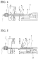
- the wire pulling unit 2 comprises a slidable form or wire template member 3 that incorporates, as shown best in FIG. 11, a corresponding plurality of guides 4 that respectively receive the wires 1 fed from the wire measuring and feeding unit 12, and a wire engaging means 6 for catching and holding the leading end of each of the harness wires 1 near the entrances 102 of each of the template member wire guides 4.
- the template member 3 is of a predetermined length that is equal to a desired length of wire to be pulled from the wire supply reels 11 and the guides 4 thereof may take any desired form so long as they contain the wires 1 therein, such as hollow channels 104.
- the template member 3 is mounted on a linear guide bearing assembly 28, which is driven back and forth in its reciprocating movement by an associated drive means, such as a primary piston and cylinder assembly 29 and a secondary piston and cylinder assembly 30.
- the wire engagement means 6 includes a harness wire set clamp 31 and a piston and cylinder drive assembly 32.
- the wire engagement means 6 is secured near the front end 5 of the template member 3 for catching and holding the leading ends 8 of the wires 1 in place near the front end 5 thereof.
- the apparatus 100 includes a means for aligning the ends of the harness wires 1.
- This wire end alignment means includes, at each wire guide 4 of the template member 3, an alignment thrust pin 7 for aligning the leading free ends 8 of the wire 1 in a common, lateral alignment.
- the alignment thrust pins 7 are fixed to an associated pin support 33, that is driven by a suitable drive means, such as an associated piston-and-cylinder drive 34.
- the primary and secondary piston and cylinder assemblies 29 and 30 are actuated, thereby causing the template member 3 to move forward from the initial position of FIG. 2 to the subsequent position of FIG. 3, where the front end 5 of the template member 3 is now in close proximity to the leading ends 8 of the wires 1 ready to be fed from the wire measuring and feeding unit 12.
- the forward ends of the wire alignment thrust pins 7 remain within the guides 4 of the template member 3 near the rear of the template member 3 as illustrated in FIG. 3.
- the wire feeding mechanism 21 and the wire measuring and feeding unit 12 is actuated to thereby feed the harness wires 1 into the guides 4 of the template member 3. This wire feeding continues until the leading ends of the wires 1 make contact with the thrust pins 7 and abut thereagainst. At this position a first predetermined length F1 for each of the harness wires extending in the guide pieces 4 of the guide template 3 is determined, as seen in FIG. 4.
- the primary piston and cylinder assembly 29 is actuated to partially withdraw the template member 3.
- the piston and cylinder assembly 32 is actuated to bring the harness wire set clamp 31 into contact with the harness wire set 1 to hold the leading free ends 8 thereof in position.
- the wire pulling unit 2 in effect draws out a length of the wire set that is approximately equal to the length of the template member.
- the lateral alignment of the leading ends 8 of the wires 1 and the feeding-out of the electric wires 1 from the wire measuring and feeding unit 12 occurs as illustrated in FIG. 6.
- the lateral aligning of the leading ends 8 of the electric wires 1 is effected by actuating the piston and cylinder drive assembly 34, to thereby drive the alignment thrust pins 7 through the wire guides 4 of the template member 3 into contact with the wires 1.
- the feeding out of the wires occurs in the direction of arrow F2 to complete the length of the wire harness required. This feeding occurs by the wire feed mechanism 21.
- the wire-to-wire interval setting unit 20 may be actuated by its associated piston-and-cylinder drive assembly 36 to place the harness wires 1 in predetermined intervals or pitches P as is required for the wire harnesses to be made.
- a loop L may be formed in the harness wires 1 as illustrated in FIG. 6.
- the cylinder assemblies 25a, 25b are actuated to drive the upper and lower clamps 24a, 24b into engagement with the harness wires 1 to catch and hold the set of measured harness wires 1 as illustrated.
- two opposing blades 26a and 26b are actuated by their respective associated upper and lower piston and cylinder drive assemblies 27a, 27b and brought into contact with the measured harness wires 1 in order to cut them.
- the harness wire set is then released from the wire engagement means 6.
- the secondary piston and cylinder drive sub assembly 30 is actuated to withdraw the template member 3 from the leading ends of the wires 1.
- the piston and cylinder drive assembly 36 is thereupon activated to withdraw the wire interval setting unit 20 from engagement with the harness wires 1, which now remain in their required intervals.
- the wire feeding mechanism 21 of the wire measuring and feeding unit 12 is actuated to withdraw the next set of leading ends of the wires 1 generally in the direction indicated by arrow R of FIG. 9 so that this next set of leading wire ends are positioned in the outlet 110 of the wire measuring and feeding unit 12.
- the wire clamping and shifting unit 14 is actuated to bring the cut and measured harness wire set 112 downstream to the connector termination means 13a and 13b where connectors 9a, 9b are terminated thereto, such as by crimping, insulation displacement or other suitable termination process.
- all components are allowed to return to the initial position of the apparatus 100 as shown in FIG. 2.
- the set 112 of cut harness wires 1 are brought to the connector termination units 13a, 13b, at which electric connectors 9a, 9b are terminated to their opposing ends of the harness wires as illustrated FIG. 10. These completed wire harnesses are then passed through the testing units 17a, 17b for checking of the harnesses, and through the eliminators 18a, 18b for removing defective harnesses, if any. Finally, complete wire harnesses are provided.
- the wires 1 will enter the guides 4 of the wire template member 3. This movement of the wires has the effect of pulling the wires from the wire measuring and feeding unit 12 for a first predetermined length while the leading ends of the wires 1 are aligned in both proper lateral spacing and alignment of the leading ends, thereby eliminating the necessity of further primping and pulling the leading ends 8 of the electric wires 1 to align them together as in the prior art.
Landscapes
- Engineering & Computer Science (AREA)
- Manufacturing & Machinery (AREA)
- Manufacturing Of Electrical Connectors (AREA)
Applications Claiming Priority (2)
| Application Number | Priority Date | Filing Date | Title |
|---|---|---|---|
| JP175569/96 | 1996-06-14 | ||
| JP8175569A JP2992678B2 (ja) | 1996-06-14 | 1996-06-14 | 電線圧接装置に於ける電線引き出し部の電線引き出し機構 |
Publications (2)
| Publication Number | Publication Date |
|---|---|
| EP0813271A2 true EP0813271A2 (de) | 1997-12-17 |
| EP0813271A3 EP0813271A3 (de) | 1998-11-25 |
Family
ID=15998381
Family Applications (1)
| Application Number | Title | Priority Date | Filing Date |
|---|---|---|---|
| EP97109346A Withdrawn EP0813271A3 (de) | 1996-06-14 | 1997-06-10 | Drahtendeführungsvorrichtung für Crimpgerät |
Country Status (3)
| Country | Link |
|---|---|
| US (1) | US5943751A (de) |
| EP (1) | EP0813271A3 (de) |
| JP (1) | JP2992678B2 (de) |
Cited By (2)
| Publication number | Priority date | Publication date | Assignee | Title |
|---|---|---|---|---|
| WO2009036979A1 (en) * | 2007-09-21 | 2009-03-26 | Tyco Electronics Amp Gmbh | Harness making device and method for the production of cable harnesses |
| EP2590275A1 (de) * | 2011-11-02 | 2013-05-08 | Schleuniger Holding AG | Leitungspositionierungsvorrichtung |
Families Citing this family (13)
| Publication number | Priority date | Publication date | Assignee | Title |
|---|---|---|---|---|
| US7798180B2 (en) * | 2002-08-30 | 2010-09-21 | Molex Incorporated | Harness fabricating apparatus |
| JP2006164568A (ja) * | 2004-12-02 | 2006-06-22 | Tyco Electronics Amp Kk | ハーネス製造装置及び製造方法 |
| ITPD20050297A1 (it) * | 2005-10-12 | 2007-04-13 | K M I Trade Srl | Attrezzatura per la realizzazione di cablaggi elettrici |
| US9484722B2 (en) * | 2009-03-23 | 2016-11-01 | Southwire Company, Llc | Pulling head assembly workstation |
| WO2011046998A1 (en) | 2009-10-14 | 2011-04-21 | Southwire Company | Pulling head assembly workstation |
| CN102074312B (zh) * | 2010-12-23 | 2012-06-27 | 昆山联滔电子有限公司 | 线缆u型成型装置 |
| JP5405618B2 (ja) * | 2012-04-26 | 2014-02-05 | 日本航空電子工業株式会社 | 電線ホルダ並びにそれを用いたハーネスの製造装置及び製造方法 |
| CN103414085B (zh) * | 2013-07-24 | 2015-12-23 | 昆山迈致治具科技有限公司 | 一种导线送料治具 |
| US20170331267A1 (en) * | 2016-05-13 | 2017-11-16 | Bentek Corporation | Apparatus and process for constructing a cable harness |
| US10867726B2 (en) * | 2017-07-13 | 2020-12-15 | John D Tillotson, JR. | Wire inventory indexing system |
| US11424583B2 (en) * | 2019-06-19 | 2022-08-23 | Blooming International Limited | Serially-connectable light string |
| WO2021154408A1 (en) * | 2020-01-28 | 2021-08-05 | Tillotson John D Jr | Wire inventory indexing system |
| CN112139406B (zh) * | 2020-09-25 | 2025-06-27 | 安费诺电子装配(厦门)有限公司 | 信号线切割装置 |
Family Cites Families (11)
| Publication number | Priority date | Publication date | Assignee | Title |
|---|---|---|---|---|
| BE625128A (de) * | 1961-11-28 | |||
| US4136440A (en) * | 1977-07-12 | 1979-01-30 | Amp Incorporated | Electrical harness fabrication method and apparatus |
| US4175316A (en) * | 1978-06-05 | 1979-11-27 | Artos Engineering Company | Wire lead clamping mechanism for wire lead production apparatus |
| AU542680B2 (en) * | 1980-03-31 | 1985-03-07 | Amp Incorporated | Wired electrical connectors |
| US4363167A (en) * | 1980-08-11 | 1982-12-14 | Amp Incorporated | Method of terminating leading ends of a plurality of wires |
| US4439919A (en) * | 1980-11-14 | 1984-04-03 | Burndy Corporation | Automatic lead making apparatus |
| US4404743A (en) * | 1981-05-26 | 1983-09-20 | Amp Incorporated | Electrical harness fabrication using improved wire measuring method |
| DE3939310A1 (de) * | 1989-11-28 | 1991-05-29 | Grote & Hartmann | Verfahren und vorrichtung zur automatischen herstellung von elektrischen modulen |
| GB9001978D0 (en) * | 1990-01-29 | 1990-03-28 | Amp Gmbh | Wire spreading device |
| JP3209444B2 (ja) * | 1992-04-07 | 2001-09-17 | タイコエレクトロニクスアンプ株式会社 | 電気コネクタ用結線装置 |
| JP2932142B2 (ja) * | 1993-12-29 | 1999-08-09 | モレックス インコーポレーテッド | 複数の電線配列間隔変換装置 |
-
1996
- 1996-06-14 JP JP8175569A patent/JP2992678B2/ja not_active Expired - Lifetime
-
1997
- 1997-06-05 US US08/869,435 patent/US5943751A/en not_active Expired - Fee Related
- 1997-06-10 EP EP97109346A patent/EP0813271A3/de not_active Withdrawn
Cited By (6)
| Publication number | Priority date | Publication date | Assignee | Title |
|---|---|---|---|---|
| WO2009036979A1 (en) * | 2007-09-21 | 2009-03-26 | Tyco Electronics Amp Gmbh | Harness making device and method for the production of cable harnesses |
| RU2483405C2 (ru) * | 2007-09-21 | 2013-05-27 | Тайко Электроникс Амп Гмбх | Машина для получения жгутов и способ получения кабельных жгутов |
| EP2590275A1 (de) * | 2011-11-02 | 2013-05-08 | Schleuniger Holding AG | Leitungspositionierungsvorrichtung |
| WO2013064916A1 (en) | 2011-11-02 | 2013-05-10 | Schleuniger Holding Ag | Wire positioning device |
| CN104025396A (zh) * | 2011-11-02 | 2014-09-03 | 施洛伊尼格控股有限公司 | 电线定位装置 |
| US9793671B2 (en) | 2011-11-02 | 2017-10-17 | Schleuniger Holding Ag | Wire positioning device |
Also Published As
| Publication number | Publication date |
|---|---|
| JPH1012062A (ja) | 1998-01-16 |
| EP0813271A3 (de) | 1998-11-25 |
| US5943751A (en) | 1999-08-31 |
| JP2992678B2 (ja) | 1999-12-20 |
Similar Documents
| Publication | Publication Date | Title |
|---|---|---|
| US5943751A (en) | Wire end alignment assembly for wire crimping apparatus | |
| US5230147A (en) | Electrical hardness termination apparatus and method | |
| JPS6039787A (ja) | 端子圧着電線の自動成形装置 | |
| US4454652A (en) | Method of processing end portions of covered wires | |
| EP0147081B1 (de) | Drahtlängenwandelvorrichtung in Zusammenhang mit einem Apparat zur Herstellung von elektrischen Drahtbäumen | |
| US4136440A (en) | Electrical harness fabrication method and apparatus | |
| US4126935A (en) | Method and apparatus for manufacturing wiring harnesses | |
| DE69409218T2 (de) | Verfahren und Vorrichtung zum Wickeln eines Bandes | |
| US4404743A (en) | Electrical harness fabrication using improved wire measuring method | |
| US4409734A (en) | Harness making apparatus and method | |
| US4290179A (en) | Cable harness assembly machine | |
| CN114365239B (zh) | 用于自动地缠绕缆线股的组装头以及方法 | |
| WO1989005047A1 (en) | Electrical cable-making apparatus | |
| US4976294A (en) | Method and apparatus for making specified-length wires for wire harness | |
| US5933932A (en) | Apparatus for making electrical harness | |
| US4630353A (en) | Insulation covering stripping device | |
| US5842266A (en) | Apparatus for producing wire harnesses | |
| US4977934A (en) | Multiple wire straightener module for an automated cable assembly system | |
| EP0801826A1 (de) | Gerät zur herstellung von kabelbäumen | |
| EP0601474B1 (de) | Drahtlängen-Messeinrichtung | |
| US7032300B2 (en) | Wire insulation displacement connection apparatus with pitch conversion mechanism | |
| EP0216464B1 (de) | Verfahren und Vorrichtung zur Herstellung eines elektrischen Kabelbaumes | |
| US5033186A (en) | Apparatus for assembling terminated wires into connectors to form electrical harnesses | |
| EP0708506A2 (de) | Zuführvorrichtung für eine Verbinderanschlussvorrichtung | |
| JPH0515012B2 (de) |
Legal Events
| Date | Code | Title | Description |
|---|---|---|---|
| PUAI | Public reference made under article 153(3) epc to a published international application that has entered the european phase |
Free format text: ORIGINAL CODE: 0009012 |
|
| AK | Designated contracting states |
Kind code of ref document: A2 Designated state(s): DE FR GB IT |
|
| PUAL | Search report despatched |
Free format text: ORIGINAL CODE: 0009013 |
|
| AK | Designated contracting states |
Kind code of ref document: A3 Designated state(s): AT BE CH DE DK ES FI FR GB GR IE IT LI LU MC NL PT SE |
|
| 17P | Request for examination filed |
Effective date: 19990415 |
|
| AKX | Designation fees paid |
Free format text: DE FR GB IT |
|
| STAA | Information on the status of an ep patent application or granted ep patent |
Free format text: STATUS: THE APPLICATION HAS BEEN WITHDRAWN |
|
| 18W | Application withdrawn |
Withdrawal date: 20020223 |