EP0813334A2 - Procédé pour définir une zone d'image détaillée à résolution complète pour visualisation pendant le balayage - Google Patents
Procédé pour définir une zone d'image détaillée à résolution complète pour visualisation pendant le balayage Download PDFInfo
- Publication number
- EP0813334A2 EP0813334A2 EP97201671A EP97201671A EP0813334A2 EP 0813334 A2 EP0813334 A2 EP 0813334A2 EP 97201671 A EP97201671 A EP 97201671A EP 97201671 A EP97201671 A EP 97201671A EP 0813334 A2 EP0813334 A2 EP 0813334A2
- Authority
- EP
- European Patent Office
- Prior art keywords
- high resolution
- image data
- scan
- resolution image
- image
- Prior art date
- Legal status (The legal status is an assumption and is not a legal conclusion. Google has not performed a legal analysis and makes no representation as to the accuracy of the status listed.)
- Withdrawn
Links
- 238000000034 method Methods 0.000 title claims description 16
- 238000013459 approach Methods 0.000 description 1
- 230000001419 dependent effect Effects 0.000 description 1
- 230000000873 masking effect Effects 0.000 description 1
- 230000004048 modification Effects 0.000 description 1
- 238000012986 modification Methods 0.000 description 1
Images


Classifications
-
- H—ELECTRICITY
- H04—ELECTRIC COMMUNICATION TECHNIQUE
- H04N—PICTORIAL COMMUNICATION, e.g. TELEVISION
- H04N1/00—Scanning, transmission or reproduction of documents or the like, e.g. facsimile transmission; Details thereof
- H04N1/387—Composing, repositioning or otherwise geometrically modifying originals
- H04N1/3872—Repositioning or masking
- H04N1/3873—Repositioning or masking defined only by a limited number of coordinate points or parameters, e.g. corners, centre; for trimming
- H04N1/3875—Repositioning or masking defined only by a limited number of coordinate points or parameters, e.g. corners, centre; for trimming combined with enlarging or reducing
Definitions
- the present invention relates in general to scanning systems. More specifically, the present invention provides a method for selecting and viewing a portion of a scanned image in full resolution during scanning to simplify the workflow and computing resources required to perform a quality check on the scanned image.
- Acquiring high resolution digital image data from a scanner is traditionally done in a multiple step process. Usually a low resolution image is scanned, on which cropping, rotation, and other image processing operations are performed. Once the operator is pleased with the result on the low resolution image, a final image is scanned at higher resolution. The image processing steps performed on the low resolution image are automatically applied to the high resolution image during or after it is scanned.
- the high resolution image may be scanned directly to disk, or it may appear in the operators window. Regardless of the output location, the high resolution image usually must be checked for image quality, since there are details in the high resolution image that cannot be seen in the low resolution version, and some image processing operations are resolution dependent, like descreening and unsharp masking. These operations cannot be accurately previewed on the low resolution image.
- a sample of the image may be scanned at high resolution, before scanning the entire image at high resolution, but this can be very time consuming relative to scanning the whole image with the hope that the quality will be good enough.
- the final quality check requires the operator to wait while the relatively large high resolution image is scanned, processed and displayed on his screen. Or, the operator must reload the final image at a later time.
- Viewing these large images usually involves examining a scaled down version of the image, similar to the low resolution image, and selecting a portion of the image to view at full resolution.
- the scaled down version of the image is either made in advance and saved on disk, or created on the fly as the image is loaded from disk. These steps consume time and memory.
- the present invention provides a method for selecting and viewing a detail area of a scanned image in full resolution during scanning to perform a quality check on the scanned image.
- the method generally includes the following steps:
- the present invention offers many advantages over the traditional quality checking approaches of the prior art.
- First, the invention allows an operator to specify at least one area of a low resolution scan that may need quality checking. This is done prior to a high resolution scan of the image.
- the high resolution image data corresponding to a selected area is available, it is automatically displayed in a separate detail window, preferably at a 1:1 ratio (1 display pixel for 1 data pixel).
- the operator can then accept or reject the high resolution scan, based on the selected area of high resolution image data displayed in the detail window, without having to load into memory and view the entire high resolution image at a 1:1 ratio.
- the high resolution image data displayed in the detail window is "tapped" out during the high resolution scan, thereby requiring no additional scanning steps. If the high resolution image data displayed in the detail window is acceptable to the operator, no time has been lost since no extra scanning steps were needed to create these detail views.
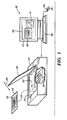
- a scanning system 10 is configured for the scanning of a reflective original 12.
- the reflective original 12 is placed with the surface 14 containing the image 16 to be scanned facing down on a transparent scanning surface 18 , and held in place by a cover 20.
- the surface is illuminated from below by lamps 22, producing a scan line 24 .
- the scanning optics and sensor electronics are located in a scan module 26, which is driven together with lamps 22 to move the scan line 24 across the length of the original 12, thereby scanning the original 12 to produce a digital representation thereof.
- the cover 20 is pivotally secured on one side to the main body of the scanning system 10 via a hinge mechanism (not shown), thereby allowing the cover 20 to be raised and lowered (directional arrow 28 ) to position one or more reflective originals 12 on the transparent scanning surface 18 .
- a digital representation of an image 30 is displayed on the display 31 of a workstation 32.
- An image modification tool 34 forming a portion of the scanner driver controlling the operation of the scanning system 10 , or accessed via a stand-alone image editing program such as Adobe's PHOTOSHOPTM, can be used if necessary, to modify various characteristics of the digital image 30 .
- FIG. 2 illustrates a low resolution preview scan 40 of an image as displayed on the display 31 of the workstation 32 .
- the image has been cropped 42 to specify the portion of the image to be scanned in high resolution.
- a scanning operator has selected at least one detail area 44 of the cropped portion 42 of the image to be viewed in high resolution during a subsequent high resolution scan.
- the high resolution image data is stored line by line to disk (not shown).
- the high resolution image data corresponding to the detail area 44 is displayed in a separate detail window 46 after it becomes available during the high resolution scan.
- the high resolution scan of the cropped portion 42 of the image starts at the top 48 of the image and progresses downward toward the bottom 50 of the image.
- the high resolution scan continues in a normal manner, with the high resolution image data stored to disk, until the current scan line 52 passes beyond the detail area 44 .
- the partially completed high resolution scan is indicated by arrow 54 .
- the high resolution image data corresponding to the detail area 44 is output from disk and displayed within the detail window 46 . If the quality of the image data within the detail window 46 is satisfactory, the high resolution scan continues (arrow 56 ) until the scan is complete. If the quality of the image data within the detail window 46 is unsatisfactory, however, the operator can prematurely terminate the scan.
- a flowchart 60 describing the general operational flow of the present invention is illustrated in FIG. 6 .
- a low resolution preview scan of an image is performed in block 62 .
- the scanning operator examines the preview scan, specifies (block 63 ) a portion of the preview scan (e.g., via cropping) to be scanned at high resolution, and selects (block 64 ) at least one detail area within the specified portion of the preview scan for use in determining the quality of the high resolution scan.
- the operator initiates the high resolution scan of the specified portion of the preview scan (block 66 ), with the high resolution scan data stored line by line to disk (block 68 ).
- the high resolution scan continues (loop 70 ) until the high resolution image data corresponding to the selected detail area is completely available (block 72 ).
- the high resolution image data corresponding to the selected detail area is read from disk and displayed in its entirety in a separate detail window (block 74 ). Meanwhile, the high resolution scan continues uninterrupted until complete (block 76 , loop 78 ). However, if the high resolution image data displayed within the detail window is deemed unacceptable (block 80 ), the operator can prematurely terminate the high resolution scan (block 82 ).
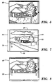
- the detail window 46 can be filled on a line by line basis with high resolution image data as the scan line 52 moves across the detail area 44 . This is illustrated in FIGS. 7-8 . As shown, the detail window 46 only contains high resolution image data for the previously scanned portion of the detail area 44 . The amount of displayed high resolution data increases (arrow 90 ) as the current scan line 52 passes over the detail area 44 . The high resolution image data for each scan line is preferably displayed in parallel with its storage to disk as soon as it is produced by the scanning system. In this embodiment, the scanning operator can reject or accept the results of the high resolution scan even before the detail window 46 has been completely filled with high resolution image data corresponding to the detail area 44 .
Landscapes
- Engineering & Computer Science (AREA)
- Multimedia (AREA)
- Signal Processing (AREA)
- Facsimile Scanning Arrangements (AREA)
- Editing Of Facsimile Originals (AREA)
- Image Input (AREA)
- Controls And Circuits For Display Device (AREA)
- Apparatus For Radiation Diagnosis (AREA)
Applications Claiming Priority (2)
| Application Number | Priority Date | Filing Date | Title |
|---|---|---|---|
| US08/661,261 US6295388B1 (en) | 1996-06-10 | 1996-06-10 | Method for selecting an area of full resolution image detail for viewing during scanning |
| US661261 | 1996-06-10 |
Publications (2)
| Publication Number | Publication Date |
|---|---|
| EP0813334A2 true EP0813334A2 (fr) | 1997-12-17 |
| EP0813334A3 EP0813334A3 (fr) | 1999-09-15 |
Family
ID=24652855
Family Applications (1)
| Application Number | Title | Priority Date | Filing Date |
|---|---|---|---|
| EP97201671A Withdrawn EP0813334A3 (fr) | 1996-06-10 | 1997-06-03 | Procédé pour définir une zone d'image détaillée à résolution complète pour visualisation pendant le balayage |
Country Status (3)
| Country | Link |
|---|---|
| US (1) | US6295388B1 (fr) |
| EP (1) | EP0813334A3 (fr) |
| JP (1) | JPH1074252A (fr) |
Cited By (6)
| Publication number | Priority date | Publication date | Assignee | Title |
|---|---|---|---|---|
| FR2787611A1 (fr) * | 1998-12-18 | 2000-06-23 | Synaps | Procede et dispositif de controle de conformite d'un support a plat |
| EP1073991A1 (fr) * | 1998-04-30 | 2001-02-07 | C Technologies AB | Enregistrement d'informations |
| EP0991263A3 (fr) * | 1998-10-01 | 2003-08-13 | Hewlett-Packard Company, A Delaware Corporation | Interface utilsateur pour déclencher un balayage final utilisant déclenchement et lâchage |
| EP0991265A3 (fr) * | 1998-10-01 | 2003-08-27 | Hewlett-Packard Company, A Delaware Corporation | Fonction de surlignage dans une interface utilisateur pour obtenir une entrée dirigée pour le traitement d'images |
| EP1206117A3 (fr) * | 2000-11-08 | 2005-04-20 | Xerox Corporation | Procédé et appareil de saisie, de sélection et de copie d'images |
| CN105793918A (zh) * | 2013-09-27 | 2016-07-20 | 皇家飞利浦有限公司 | 同时显示多个视频源的视频数据 |
Families Citing this family (8)
| Publication number | Priority date | Publication date | Assignee | Title |
|---|---|---|---|---|
| JPH11175699A (ja) * | 1997-12-12 | 1999-07-02 | Fuji Photo Film Co Ltd | 画像処理装置 |
| WO1999040725A1 (fr) * | 1998-02-10 | 1999-08-12 | Nihon Computer Co., Ltd. | Procede de transfert video a forte valeur ajoutee haute resolution au moyen d'image pseudo-naturelle, unite de traitement video, procede de traitement video et systeme de transfert a forte valeur ajoutee haute resolution, ainsi que support de stockage |
| US6674901B1 (en) * | 1999-04-21 | 2004-01-06 | Hewlett-Packard Development Company, L.P. | Document analysis system and method |
| US6965460B1 (en) * | 2000-08-08 | 2005-11-15 | Hewlett-Packard Development Company, L.P. | Method and system for scanning an image using a look-down linear array scanner |
| US7440146B2 (en) * | 2001-09-20 | 2008-10-21 | Transpacific Ip, Llp | Scanning method and scanning system free of identifying original's attribute |
| US20040042684A1 (en) * | 2002-09-03 | 2004-03-04 | Linda Liu | Method for scanning the irregular object |
| US7639392B2 (en) * | 2003-03-28 | 2009-12-29 | Infoprint Solutions Company, Llc | Methods, systems, and media to enhance image processing in a color reprographic system |
| US11889986B2 (en) | 2010-12-09 | 2024-02-06 | Endochoice, Inc. | Flexible electronic circuit board for a multi-camera endoscope |
Family Cites Families (10)
| Publication number | Priority date | Publication date | Assignee | Title |
|---|---|---|---|---|
| DE2516191A1 (de) * | 1975-04-14 | 1976-10-28 | Siemens Ag | Verfahren zum uebertragen von bildern aus einem zentralen bildspeicher in fernmelde-, insbesondere fernsprechanlagen zu einem bildwiedergabegeraet |
| EP0202014B1 (fr) * | 1985-04-13 | 1996-02-28 | Quantel Limited | Systèmes de création d'images vidéo |
| US4712142A (en) * | 1985-08-27 | 1987-12-08 | Mitsubishi Denki Kabushiki Kaisha | Image pickup apparatus with range specification of displayed image |
| US4656524A (en) * | 1985-12-23 | 1987-04-07 | Polaroid Corporation | Electronic imaging copier |
| JP2508673B2 (ja) * | 1986-12-17 | 1996-06-19 | ソニー株式会社 | 表示装置 |
| US4888812A (en) | 1987-12-18 | 1989-12-19 | International Business Machines Corporation | Document image processing system |
| US4837635A (en) | 1988-01-22 | 1989-06-06 | Hewlett-Packard Company | A scanning system in which a portion of a preview scan image of a picture displaced on a screen is selected and a corresponding portion of the picture is scanned in a final scan |
| US5185662A (en) * | 1991-01-28 | 1993-02-09 | Eastman Kodak Company | Method and apparatus for producing copy with selective area treatment |
| US5222154A (en) * | 1991-06-12 | 1993-06-22 | Hewlett-Packard Company | System and method for spot color extraction |
| JPH05181443A (ja) * | 1991-07-01 | 1993-07-23 | Seiko Epson Corp | コンピュータ |
-
1996
- 1996-06-10 US US08/661,261 patent/US6295388B1/en not_active Expired - Fee Related
-
1997
- 1997-06-03 EP EP97201671A patent/EP0813334A3/fr not_active Withdrawn
- 1997-06-09 JP JP9164884A patent/JPH1074252A/ja active Pending
Cited By (8)
| Publication number | Priority date | Publication date | Assignee | Title |
|---|---|---|---|---|
| EP1073991A1 (fr) * | 1998-04-30 | 2001-02-07 | C Technologies AB | Enregistrement d'informations |
| EP0991263A3 (fr) * | 1998-10-01 | 2003-08-13 | Hewlett-Packard Company, A Delaware Corporation | Interface utilsateur pour déclencher un balayage final utilisant déclenchement et lâchage |
| EP0991265A3 (fr) * | 1998-10-01 | 2003-08-27 | Hewlett-Packard Company, A Delaware Corporation | Fonction de surlignage dans une interface utilisateur pour obtenir une entrée dirigée pour le traitement d'images |
| FR2787611A1 (fr) * | 1998-12-18 | 2000-06-23 | Synaps | Procede et dispositif de controle de conformite d'un support a plat |
| WO2000038114A1 (fr) * | 1998-12-18 | 2000-06-29 | Synaps | Procede et dispositif de controle de conformite d'un support a plat en reference d'un modele defini |
| EP1206117A3 (fr) * | 2000-11-08 | 2005-04-20 | Xerox Corporation | Procédé et appareil de saisie, de sélection et de copie d'images |
| CN105793918A (zh) * | 2013-09-27 | 2016-07-20 | 皇家飞利浦有限公司 | 同时显示多个视频源的视频数据 |
| CN105793918B (zh) * | 2013-09-27 | 2019-01-22 | 皇家飞利浦有限公司 | 同时显示多个视频源的视频数据 |
Also Published As
| Publication number | Publication date |
|---|---|
| EP0813334A3 (fr) | 1999-09-15 |
| US6295388B1 (en) | 2001-09-25 |
| JPH1074252A (ja) | 1998-03-17 |
Similar Documents
| Publication | Publication Date | Title |
|---|---|---|
| US6295388B1 (en) | Method for selecting an area of full resolution image detail for viewing during scanning | |
| US6954284B2 (en) | Index print producing method, image processing system, image processing method and image processing device | |
| US6765691B2 (en) | Method and apparatus for converting original image data to density data for forming an image on photosensitive material and for displaying an image on a monitor | |
| US5889578A (en) | Method and apparatus for using film scanning information to determine the type and category of an image | |
| US7072526B2 (en) | Image processing apparatus, image processing method and recording medium | |
| US7515313B2 (en) | Method and system for scanning with one-scan-and-done feature | |
| EP0502369B1 (fr) | Procédé et appareil de traitement d'images par la mise au point des conditions de traitement d'image basée sur des indications de finition | |
| US20070030540A1 (en) | Image scanning | |
| US6317221B1 (en) | Image reading device and method | |
| CN101729723A (zh) | 图像读取方法和图像读取设备 | |
| JPH11191841A (ja) | 画像処理装置 | |
| EP0500112B1 (fr) | Appareil et procédé de lecture d'images pour la détermination automatique de la zone d'image dans une zone de lecture plus large | |
| US6201613B1 (en) | Automatic image enhancement of halftone and continuous tone images | |
| EP1377023A1 (fr) | Système de balayage et de traitement d'image, méthode de balayage et traitement d' une image, et méthode de sélection d'une d'une pluralité de fichier maitres comportant des données encodant une image balayée | |
| CN101202804B (zh) | 图像读取系统的控制方法 | |
| US20060165291A1 (en) | Picture editing | |
| US4635108A (en) | Scanner-previewer combination including a programmable sampling circuit for permitting an entire frame of an original to be stored in a fixed-capacity memory | |
| JP2004032167A (ja) | 画像読取システムおよび画像読取処理プログラム | |
| JPH1117890A (ja) | 原稿画像を走査する為の方法及び装置 | |
| US20020154343A1 (en) | System and method of capturing a digital picture | |
| US20040212849A1 (en) | Image reading device, program and method | |
| JPH11194866A (ja) | 画像処理装置 | |
| JP3740150B2 (ja) | インデックスプリント作成方法 | |
| JP2000083172A (ja) | 画像処理装置 | |
| JP2000011140A (ja) | 画像処理装置 |
Legal Events
| Date | Code | Title | Description |
|---|---|---|---|
| PUAI | Public reference made under article 153(3) epc to a published international application that has entered the european phase |
Free format text: ORIGINAL CODE: 0009012 |
|
| AK | Designated contracting states |
Kind code of ref document: A2 Designated state(s): BE DE FR GB |
|
| RAP1 | Party data changed (applicant data changed or rights of an application transferred) |
Owner name: AGFA CORPORATION |
|
| PUAL | Search report despatched |
Free format text: ORIGINAL CODE: 0009013 |
|
| RAP1 | Party data changed (applicant data changed or rights of an application transferred) |
Owner name: AGFA CORPORATION |
|
| AK | Designated contracting states |
Kind code of ref document: A3 Designated state(s): AT BE CH DE DK ES FI FR GB GR IE IT LI LU MC NL PT SE |
|
| 17P | Request for examination filed |
Effective date: 20000315 |
|
| AKX | Designation fees paid |
Free format text: BE DE FR GB |
|
| STAA | Information on the status of an ep patent application or granted ep patent |
Free format text: STATUS: THE APPLICATION IS DEEMED TO BE WITHDRAWN |
|
| 18D | Application deemed to be withdrawn |
Effective date: 20041231 |