EP0813832A2 - Système de meubles, en particulier, système de meubles pour cuisines - Google Patents
Système de meubles, en particulier, système de meubles pour cuisines Download PDFInfo
- Publication number
- EP0813832A2 EP0813832A2 EP97108219A EP97108219A EP0813832A2 EP 0813832 A2 EP0813832 A2 EP 0813832A2 EP 97108219 A EP97108219 A EP 97108219A EP 97108219 A EP97108219 A EP 97108219A EP 0813832 A2 EP0813832 A2 EP 0813832A2
- Authority
- EP
- European Patent Office
- Prior art keywords
- connecting element
- furniture system
- tubes
- profiles
- here
- Prior art date
- Legal status (The legal status is an assumption and is not a legal conclusion. Google has not performed a legal analysis and makes no representation as to the accuracy of the status listed.)
- Granted
Links
- 238000005034 decoration Methods 0.000 claims description 2
- 229910052782 aluminium Inorganic materials 0.000 description 7
- XAGFODPZIPBFFR-UHFFFAOYSA-N aluminium Chemical compound [Al] XAGFODPZIPBFFR-UHFFFAOYSA-N 0.000 description 7
- 238000010276 construction Methods 0.000 description 6
- 239000000463 material Substances 0.000 description 6
- 229910052751 metal Inorganic materials 0.000 description 6
- 239000002184 metal Substances 0.000 description 6
- 239000002023 wood Substances 0.000 description 5
- 238000013459 approach Methods 0.000 description 4
- 229910000831 Steel Inorganic materials 0.000 description 3
- 238000009434 installation Methods 0.000 description 3
- 239000004033 plastic Substances 0.000 description 3
- 229910001220 stainless steel Inorganic materials 0.000 description 3
- 239000010935 stainless steel Substances 0.000 description 3
- 239000010959 steel Substances 0.000 description 3
- 230000008719 thickening Effects 0.000 description 3
- XEEYBQQBJWHFJM-UHFFFAOYSA-N Iron Chemical compound [Fe] XEEYBQQBJWHFJM-UHFFFAOYSA-N 0.000 description 2
- 229910000746 Structural steel Inorganic materials 0.000 description 2
- 238000004026 adhesive bonding Methods 0.000 description 2
- 239000000428 dust Substances 0.000 description 2
- 239000013013 elastic material Substances 0.000 description 2
- 230000004048 modification Effects 0.000 description 2
- 238000012986 modification Methods 0.000 description 2
- 238000002360 preparation method Methods 0.000 description 2
- 238000003466 welding Methods 0.000 description 2
- 235000004443 Ricinus communis Nutrition 0.000 description 1
- 240000000528 Ricinus communis Species 0.000 description 1
- 239000000853 adhesive Substances 0.000 description 1
- 230000001070 adhesive effect Effects 0.000 description 1
- 230000000712 assembly Effects 0.000 description 1
- 238000000429 assembly Methods 0.000 description 1
- 238000005452 bending Methods 0.000 description 1
- 230000015572 biosynthetic process Effects 0.000 description 1
- 239000011093 chipboard Substances 0.000 description 1
- 239000006260 foam Substances 0.000 description 1
- 239000011521 glass Substances 0.000 description 1
- 239000010438 granite Substances 0.000 description 1
- 229910052742 iron Inorganic materials 0.000 description 1
- 239000010410 layer Substances 0.000 description 1
- 239000007788 liquid Substances 0.000 description 1
- 238000003801 milling Methods 0.000 description 1
- 239000000123 paper Substances 0.000 description 1
- 238000005192 partition Methods 0.000 description 1
- 239000011120 plywood Substances 0.000 description 1
- 239000002356 single layer Substances 0.000 description 1
- 125000006850 spacer group Chemical group 0.000 description 1
- 230000003068 static effect Effects 0.000 description 1
- 239000004575 stone Substances 0.000 description 1
- 238000011144 upstream manufacturing Methods 0.000 description 1
- 238000005406 washing Methods 0.000 description 1
Images


Classifications
-
- F—MECHANICAL ENGINEERING; LIGHTING; HEATING; WEAPONS; BLASTING
- F16—ENGINEERING ELEMENTS AND UNITS; GENERAL MEASURES FOR PRODUCING AND MAINTAINING EFFECTIVE FUNCTIONING OF MACHINES OR INSTALLATIONS; THERMAL INSULATION IN GENERAL
- F16B—DEVICES FOR FASTENING OR SECURING CONSTRUCTIONAL ELEMENTS OR MACHINE PARTS TOGETHER, e.g. NAILS, BOLTS, CIRCLIPS, CLAMPS, CLIPS OR WEDGES; JOINTS OR JOINTING
- F16B12/00—Jointing of furniture or the like, e.g. hidden from exterior
- F16B12/44—Leg joints; Corner joints
-
- A—HUMAN NECESSITIES
- A47—FURNITURE; DOMESTIC ARTICLES OR APPLIANCES; COFFEE MILLS; SPICE MILLS; SUCTION CLEANERS IN GENERAL
- A47B—TABLES; DESKS; OFFICE FURNITURE; CABINETS; DRAWERS; GENERAL DETAILS OF FURNITURE
- A47B77/00—Kitchen cabinets
-
- A—HUMAN NECESSITIES
- A47—FURNITURE; DOMESTIC ARTICLES OR APPLIANCES; COFFEE MILLS; SPICE MILLS; SUCTION CLEANERS IN GENERAL
- A47B—TABLES; DESKS; OFFICE FURNITURE; CABINETS; DRAWERS; GENERAL DETAILS OF FURNITURE
- A47B47/00—Cabinets, racks or shelf units, characterised by features related to dismountability or building-up from elements
-
- A—HUMAN NECESSITIES
- A47—FURNITURE; DOMESTIC ARTICLES OR APPLIANCES; COFFEE MILLS; SPICE MILLS; SUCTION CLEANERS IN GENERAL
- A47B—TABLES; DESKS; OFFICE FURNITURE; CABINETS; DRAWERS; GENERAL DETAILS OF FURNITURE
- A47B88/00—Drawers for tables, cabinets or like furniture; Guides for drawers
- A47B88/40—Sliding drawers; Slides or guides therefor
- A47B88/423—Fastening devices for slides or guides
- A47B88/43—Fastening devices for slides or guides at cabinet side
-
- A—HUMAN NECESSITIES
- A47—FURNITURE; DOMESTIC ARTICLES OR APPLIANCES; COFFEE MILLS; SPICE MILLS; SUCTION CLEANERS IN GENERAL
- A47B—TABLES; DESKS; OFFICE FURNITURE; CABINETS; DRAWERS; GENERAL DETAILS OF FURNITURE
- A47B96/00—Details of cabinets, racks or shelf units not covered by a single one of groups A47B43/00 - A47B95/00; General details of furniture
- A47B96/14—Bars, uprights, struts, or like supports, for cabinets, brackets, or the like
-
- F—MECHANICAL ENGINEERING; LIGHTING; HEATING; WEAPONS; BLASTING
- F16—ENGINEERING ELEMENTS AND UNITS; GENERAL MEASURES FOR PRODUCING AND MAINTAINING EFFECTIVE FUNCTIONING OF MACHINES OR INSTALLATIONS; THERMAL INSULATION IN GENERAL
- F16B—DEVICES FOR FASTENING OR SECURING CONSTRUCTIONAL ELEMENTS OR MACHINE PARTS TOGETHER, e.g. NAILS, BOLTS, CIRCLIPS, CLAMPS, CLIPS OR WEDGES; JOINTS OR JOINTING
- F16B12/00—Jointing of furniture or the like, e.g. hidden from exterior
- F16B12/02—Joints between panels and corner posts
-
- F—MECHANICAL ENGINEERING; LIGHTING; HEATING; WEAPONS; BLASTING
- F16—ENGINEERING ELEMENTS AND UNITS; GENERAL MEASURES FOR PRODUCING AND MAINTAINING EFFECTIVE FUNCTIONING OF MACHINES OR INSTALLATIONS; THERMAL INSULATION IN GENERAL
- F16B—DEVICES FOR FASTENING OR SECURING CONSTRUCTIONAL ELEMENTS OR MACHINE PARTS TOGETHER, e.g. NAILS, BOLTS, CIRCLIPS, CLAMPS, CLIPS OR WEDGES; JOINTS OR JOINTING
- F16B12/00—Jointing of furniture or the like, e.g. hidden from exterior
- F16B12/40—Joints for furniture tubing
- F16B12/42—Joints for furniture tubing connecting furniture tubing to non-tubular parts
-
- F—MECHANICAL ENGINEERING; LIGHTING; HEATING; WEAPONS; BLASTING
- F16—ENGINEERING ELEMENTS AND UNITS; GENERAL MEASURES FOR PRODUCING AND MAINTAINING EFFECTIVE FUNCTIONING OF MACHINES OR INSTALLATIONS; THERMAL INSULATION IN GENERAL
- F16B—DEVICES FOR FASTENING OR SECURING CONSTRUCTIONAL ELEMENTS OR MACHINE PARTS TOGETHER, e.g. NAILS, BOLTS, CIRCLIPS, CLAMPS, CLIPS OR WEDGES; JOINTS OR JOINTING
- F16B12/00—Jointing of furniture or the like, e.g. hidden from exterior
- F16B12/44—Leg joints; Corner joints
- F16B12/48—Non-metal leg connections
-
- Y—GENERAL TAGGING OF NEW TECHNOLOGICAL DEVELOPMENTS; GENERAL TAGGING OF CROSS-SECTIONAL TECHNOLOGIES SPANNING OVER SEVERAL SECTIONS OF THE IPC; TECHNICAL SUBJECTS COVERED BY FORMER USPC CROSS-REFERENCE ART COLLECTIONS [XRACs] AND DIGESTS
- Y10—TECHNICAL SUBJECTS COVERED BY FORMER USPC
- Y10T—TECHNICAL SUBJECTS COVERED BY FORMER US CLASSIFICATION
- Y10T403/00—Joints and connections
- Y10T403/46—Rod end to transverse side of member
- Y10T403/4602—Corner joint
Definitions
- the invention relates to a furniture system, in particular kitchen furniture system according to the preamble of patent claim 1.
- suitablecase kitchen in which cupboards and functional units such as dishwashers, washing machines, stoves are integrated in a kind of suitcase housing that can be moved on castors and has integrated folding handles for transporting the unit.
- a furniture system in which a self-supporting basic structure is provided with tubes connected to one another by connecting elements, whereby depending on the functionality, shelf boards, side parts, wall parts, flaps, inserts or the like are used in the basic structure and whereby the wall elements are statically load-bearing parts of the furniture.
- the connection of the tubes forming the basic structure is formed by essentially spherical node elements into which the tubes are screwed by means of an end screw.
- the object of the invention is to develop a furniture system with a self-supporting basic structure, which allows a flexible design of kitchen furniture, including all functionalities, that at the same time enables high mobility and has an independent and appealing design.
- the connecting elements of the basic structure each consist of a molded part, which is itself designed as a tube and / or largely closed hollow profile, on which at least one laterally projecting shoulder, which extends over the entire length of the connecting element, is formed is.
- the connecting elements themselves are integrated as vertical components in the basic structure, which replace the pipes and / or profiles that connect them with each other over their length.
- all functionalities can be integrated using the connecting elements formed with the approach. Shelf compartments, side walls, doors, flaps and fittings, as well as drawers can be easily integrated.
- Heavy built-in devices can also be integrated due to the high load-bearing capacity.
- the design of the connecting elements not only enables a modular system that is advantageous from a technical point of view, but also gives the furniture a significant design note due to the connection of the hollow profile consisting of a tube and / or largely closed with a subsequent approach.
- the vertical elements of the basic structure can consist of tubes and / or profiles which extend into the hollow profile of the connecting elements.
- the pipes and / or profiles can extend over the entire length of the connecting element, so that the connecting element is pushed onto the hollow profile as a sleeve, so to speak.
- the hollow profiles do not extend over the entire length in the connecting element, but are only pushed in at the ends to such an extent that secure fastening in the connecting element, for example by clamping, screwing, etc., is possible. This saves material and weight.
- the horizontal pipes and / or profiles, as well as any plates, frames etc. of the basic structure that may be used can be attached of the connecting element.
- the connecting element has the shape of an asymmetrical drop in cross section.
- this shape also enables very good functionality, since no edges are formed here, which make it difficult, for example, to clean the surface.
- the connecting element can have a round or polygonal hollow profile, which is adapted to the shape of the pipes to be connected to one another.
- a recess can be provided on one side of the attachment for the flush reception of components such as wall elements, floors, frames, pipes and plates.
- decorations can be applied to the connecting element, which are engraved and / or printed, for example, in order to additionally give the furniture a designer character.
- connection elements are connected to mounting plates which as such have standardized bores, screw bores, recesses and / or grooves which serve to accommodate components and fittings to be assembled.
- These mounting plates thus contain a number of mounting options, which in particular restrict the provision of a variety of shapes for components for the furniture system. Converting the furniture system is also made easier by the multiple functionality of these mounting plates.
- the connecting element can also be formed in several parts. So the connecting element as such have a teardrop shape, but comprise an externally attachable screen to cover screws of a screw connection that are to be screwed in from the outside.
- an easy-to-install version is provided, since screwing on from the outside is guaranteed after removing the screen.
- the connecting element can also consist of a hollow profile with a shape recess extending over its length and an attachment that can be connected to this hollow profile with a corresponding shape attachment for the positive connection of the two parts.
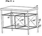
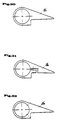
- the basic structure 12 consists in all embodiments of connecting elements 16, which are aligned vertically and into which vertical tubes 18 are also inserted in each case.
- the connecting elements 16 consist of a molded part which is itself designed as a tube and on which a laterally protruding projection 20 which extends over the entire length of the connecting element 16 is formed.
- the horizontal struts, which are designed here as square tubes 22, are attached to this extension 20.
- the basic structure of the furniture system according to the invention is thus carried out by a pipe system which is connected to one another by connecting elements 16.
- the connecting elements 16 and also the usual tubes 18, 22 preferably consist of metal, for example aluminum and stainless steel, but also of wood or plastic.
- Two floor levels are formed by the horizontally extending tubes 22.
- a plate made of metal or wood can also be connected to the connecting elements in a manner not shown here.
- FIG. 1 shows a monoblock in which a functional element, such as a device, is later formed
- the exemplary embodiment according to FIG. 2 is designed as a duoblock.
- Two devices can later be accommodated here side by side.
- the horizontal square tubes 22 are here by a central vertical support frame 24, which is also made of square tubes exists, connected to each other.
- the frame in the rear wall area can be stiffened with static aids such as ropes or rods 25 in order to avoid bending and the like.
- the embodiment according to FIG. 3 shows a high monoblock in which two functional compartments are arranged one above the other.
- a middle support level is formed by corresponding square tubes 22, the height of which can be fastened to the connecting elements 16 in a freely adjustable manner.
- the tubes 18, which are designed here as tubes with a circular cross section, are only inserted into the respective connecting element 16 to the extent that this is ensured for the necessary stability by means of appropriate connections or constructive safeguards. It is essential that the frame is self-supporting and self-stiffening and that no stability is achieved for the kitchen furniture via the usual side parts used here. As a result, no consideration needs to be given to the design of the side elements. Any functionalities can thus be accommodated in the self-supporting and self-stiffening basic structure 12.
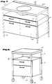
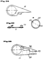
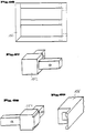
- a duo block is shown in the kitchen furniture according to FIGS. 4 and 5, which essentially contains a basic structure 12 according to the previous embodiment according to FIG. 2. Here, however, an additional horizontal plane has been drawn in to accommodate drawers 26. Larger drawers 28 are arranged in the lower area.
- a wet unit 30 is provided as the support plate 14 integrated basin, the shape of the basin differs in the embodiments according to FIGS. 4 and 5. In the rear area of the wet unit 30 there are in each case strips 32 which form a stop edge on the wet unit 30 and thus prevent objects or liquids from running behind the wet unit.
- 4a shows a wet unit 30 in which the integrated basin is arranged in a large depression 31 which has a step-shaped shoulder 33 in the rear region.
- FIG. 6 shows an example of a preparation unit in which a drawer 28 and a narrower drawer 26 are formed in the frame 12.
- a parking level 36 is formed above the narrower drawer 26.
- a worktop 14 is supported on the base frame 12.
- the preparation unit is movably supported on rollers 34 here.
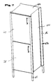
- a "high" monoblock with two devices arranged one above the other in this exemplary embodiment is formed in the basic framework 12 and has two door elements 38 and 40 arranged one above the other.
- a refrigerator is integrated in the upper region by the door element 40 in the exemplary embodiment shown here.
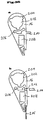
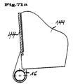
- FIG. 7a shows another embodiment of the invention, here as a "low" monoblock.
- a narrow pull-out 26 is arranged below the plate 14.
- the monoblock In the lower area, the monoblock is designed to be open, the lower level being defined by an inserted grate 158.
- the dash-dotted line indicates a plate that can be installed as an additional intermediate floor 37.
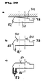
- a connecting element 16 is shown in section. It consists of a tubular hollow profile and a flag-like extension 20, the overall shape of the cross section corresponding to an asymmetrical teardrop shape, as is also shown in FIG. 11.
- the connecting element is manufactured, for example, as an aluminum profile. It can also consist of other materials, such as iron, plastic, etc.
- a tube 18 is shown inside the connecting element 16, which is connected to the connecting element 16 in a rotationally fixed manner.
- a recess is provided on the side of the connecting element, which is directed towards the inside of the furniture.
- a mounting plate 50 is screwed into this recess and is additionally inserted into a corresponding groove of the connecting element via a nose-shaped projection 52.
- the mounting plate has perforated holes, screw holes and a further groove for receiving a side wall 44 which can be screwed in accordingly.
- the more precise structure and function of the mounting plate 50 will be described in more detail below.
- a side wall 44 is inserted between the recess of the mounting plate 50 and the extension 20 and is connected to a screw connection, not shown here.
- FIG. 9 An alternative embodiment of the connecting element is shown in the embodiment according to FIG. 9, in which there is only a comparatively smaller recess for the immediate reception of a side element 44.
- the mounting plate is dispensed with.
- FIG. 10 A further alternative embodiment of the connecting element is shown in FIG. 10.
- the connecting element 16 has no recess, so that the side element 44 is screwed onto the outside of the connecting element 16. This creates a shoulder 46.
- the side element 44 is therefore not designed to be flush with the connecting element 16.
- the paragraph 46 also serves as a door stop for a door.
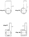
- connecting elements 16 with a drop shape which is asymmetrical in cross section are assumed, as shown in FIG. 11.
- 12 to 25 show shape variants of the connecting elements, which are the same in each case that they consist of a tube and / or largely closed hollow profile and a shoulder.
- the shape is fundamentally different.
- the hollow profile can have a contour which is circular on the inside in cross section.
- this inner contour can also be polygonal.
- a square inner contour is shown in FIGS. 21 and 23, while an octagonal inner contour is shown in FIGS. 24 and 25.
- the tubes 18 of the basic structure 12 which are not shown in any more detail here, are of course also polygonal in a form-adapted manner.
- the formation of polygons in particular makes it easier to adjust and fix a certain angle for the next connected side.
- FIGS. 11 to 25 only partial recesses are shown, into which either a side wall 44 or a mounting plate 50 can be received directly.
- the arrangement and configuration of these recesses is not limited to the embodiments shown here, but can also be applied to the other embodiments.
- FIG. 26 and 27 each show connecting elements 16, 11 correspond in their basic form to that according to FIG. 11, but on the outward-facing surface of the extension 20 facing away from the furniture, decorative grooves 56 (in FIG. 26) or 58 (in FIG. 27) are provided.
- FIG. 28 shows a profile 17 which is derived from the shape of the profile 16 according to FIG. 14 by providing two recesses.
- This connecting element 17 forms a central part with which, for example, a central post of a kitchen furniture or basic module can be realized. Additional elements (such as basic modules) can also be attached via the connecting element 17.
- mounting plates 50 not shown here, can be used in the corresponding recesses, via which horizontal pipe connections, wall parts, etc. can then be attached.
- FIG. 29 shows a connecting element 16 'in which two lugs 20 and 20' are formed at right angles to one another.
- This connecting element can serve as a corner connection in the rear basic scaffold area.
- a rear wall and a side wall can be mounted in corresponding recesses 21 or 21 '.
- FIG. 30 to 34 show different embodiments of connecting elements 16, which differ in the type of fastening of the pipe, not shown here.
- the tube 18 is connected to the connecting element 16 by a fit, by gluing or another detachable or non-detachable connection.
- FIG. 31 shows a connecting element with which the hollow profile of the connecting element is designed as a pipe clamp, so that the pipe or wheel holder 18 is clamped here by means of a corresponding clamping screw connection.
- Fig. 32 two clamping screws are indicated by dashed lines in the connecting element 16, via which a correspondingly inserted tube 18 can also be clamped.
- FIG. 33 and 34 an alternative fastening of the tube 18, which is not shown here, is shown in the connecting element 16.
- a corresponding opening 60 is provided here in the connecting element 16.
- the pipe 18 to be fixed which is shown in FIG. 33a, also has openings 62 and 64 at two points which are diametrically opposite.
- a leaf spring 66 which is shown in FIG. 33, can be pushed through the openings 60 of the connecting element 16 and the openings 62 and 64 of the tube 18 in order to fix the tube 18.
- Protrusions 68 and 70 of different heights which consist, for example, of welded nut heads, are provided for fixing the leaf spring, the protrusion 68 being less high than the protrusion 70.
- the protrusion 68 can be pushed through the comparatively higher opening 62 of the tube 18.
- the projection 70 fits into the recess 60 of the connecting element 16.
- the length of the leaf spring 66 is now dimensioned such that it comes to lie in the assembled position within the recess 64 of the tube 18 with its tongue upstream of the thickening 68, while the thickening 70th comes to rest in the recess 60 of the connecting element 16.
- the tube is secured axially and radially in the connecting element 16.
- the thickening 70 is adapted to the opening 60 so that a clamping set is implemented here.
- the connecting element 16 here has screw holes which permit screwing from the outside of the piece of furniture. After screwing from the outside, one can Screen 72 inserted over the area of the screw connections and fixed by a spring groove connection or a snap-click connection.
- the approach 20 of the connecting element 16 has a recess in which a side wall, not shown here, can be received. This is supported by a corresponding contact surface 73 and screwed according to the dashed line. Due to the different design of the screen 72 and the contact surface 73, different thicknesses of the side wall can be compensated here by exchanging the screen 72.
- 35a and 35b show further exemplary embodiments of the connecting element 16.
- These two connecting elements each have tube receptacles 202. Distributed equally over the circumference, three grooves 204 are excluded from each of these tube receptacles.
- Both connecting elements 16 also have a corresponding bore 206, which is used to fasten cover caps, which are not shown here.
- both embodiments of the connecting elements 16 comprise hollow chambers 208 for receiving corner connectors (cf. embodiment according to FIG. 60a), which are used for fastening floors.
- a projection 210 is integrally formed on the connecting element 16, which is used for fastening to the rear wall.
- a groove 212 is excluded, in which a front stop 214 can be inserted.
- a side plate 216 is inserted into a corresponding receptacle.
- FIG. 36 shows a cross-sectional illustration and a top view of the mounting plate 50, while FIGS. 37 to 39 each show only cross-sectional representations of the mounting plate.
- the mounting plate 50 according to FIG. 36 corresponds to that from FIG. 8.
- a number of pre-drilled holes and screw holes 74 which serve to accommodate standard fittings, are shown.
- a projection 52 is provided on the mounting plate 50, which is used to adjust and prevent lifting in the event of a flat load due to a side wall that applies a pressure load in the interior of the piece of furniture or an outward tensile force of a hinge that is attached in the function bar.
- the projection 52 engages in a corresponding recess in the connecting element 16 (cf. FIG. 8).
- the dimensioning of the side screw connection can be chosen smaller due to this positive engagement of the projection 52 in the corresponding recess of the connecting element 16.
- the projection 52 is arranged at a different location.
- recesses 76 are provided here, into which rubber lips (not shown here) or similar spacers can be inserted in order to compensate for different side wall thicknesses and tolerances of the side walls of side walls (not shown here) to be used, which come to rest in the recess 78. In principle, however, different side thicknesses can also be realized by means of different recesses 78.
- FIG. 38 Another embodiment of the mounting plate is shown in FIG. 38, in which recesses in the mounting plate, which are designated here by 80, are provided, these recesses serving to save weight.
- 39 shows an again varied embodiment of the mounting plate 50, which has two conical guides 82 and 84 and an integrated stop bar 86 with a seal 88.
- the seal 88 is optional and can also be omitted if necessary.
- 39a, 39b and 39c modifications of the embodiment according to FIG. 39 are shown.
- the mounting plate has an inclined contact surface 79, which, by appropriately tightening the mounting screws, enables the space formed by the recess 78 to be narrowed and thus allows it to be adapted to the side wall thickness of the side wall, which is not shown here.
- the stop bar 86 ' is integrally formed on the mounting plate 50.
- the stop bar 86 ' is covered with a U-shaped rubber bar 87.
- the mounting plate 40 shows a mounting plate 50 with a number of different functional fitting parts.
- the mounting plate 50 has a series of bores 74.
- a hinge bracket 94 also shows in the assembled position in FIG. 40.
- Various shelf supports, as are customary in construction, are shown at 96 and 98.
- the strip 100 also represents a shelf support which is fitted in a recess 90 and can be inserted there. With 102 a support angle is designated, which can be connected to the mounting plate by means of screws.
- 104 shows a frame for a floor, which can also be connected to the mounting plate via screw connections.
- the mounting plate offers a multitude of variable mounting options for the individual hardware components, components and functional parts.
- the mounting plate 50 can be perforated, as designated here with the opening 75, in order to also accommodate a frame 104 here, for example.
- the interruption 75 can also be made longer, which leads to material savings and thus to a reduction in costs and weight
- FIG. 41 shows another typical installation situation of two mounting plates 50 in perspective in the basic framework, which is not shown here.
- a side element 44 is held between the two mounting plates 50.
- a rear wall 106 shown only in section, is inserted in the rear mounting plate 50 in a corresponding groove.
- a conventional slide guide 108 is screwed laterally inwards into corresponding screw holes provided in the mounting plates 50.
- FIG. 42 shows an alternative embodiment of the rear mounting plate 50 which has an integrated stop bar 110 to which the rear wall 106 can be screwed.
- a mounting plate 50 is shown, which also has a stop bar 110 for screwing on the rear wall 106 and additionally a groove 112, into which a further partition can be inserted.
- a separate compartment in the kitchen furniture is thus formed by the further usable intermediate wall (not shown here) and the rear wall 106.
- FIG. 44 has a rear mounting plate 50 which essentially corresponds to that according to FIG. 43.
- a removable clamping strip 114 is inserted in the recess 112, which interacts with a stop strip 116 additionally molded onto the mounting plate and two rubber seals 118 in order to hold a further rear wall 120 which can be removed from the interior of the kitchen furniture.
- a fastening of a rear wall 106 is shown without the provision of an additional mounting plate.
- a connecting element 16 according to an embodiment of FIG. 35a is equipped with an integrally molded projection 210 to which the corresponding rear wall 106 can be screwed.
- a rear wall 106 is screwed to a lower floor 220 so that it protrudes vertically upwards.
- an upper base 222 is arranged with a component 224 arranged underneath, in which a groove 226 is recessed.
- a bent part of a rear wall 106, on which one or more knobs 228 are provided, is inserted into this groove 226.
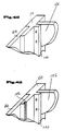
- FIGS. 45 to 49 Another construction of a connecting element 51 is shown in FIGS. 45 to 49.
- the connecting element 51 is constructed here in two parts and consists of a hollow profile 122 and a shoulder 124.
- a shaped recess is provided in the hollow profile, into which a corresponding shaped shoulder 126 of the shoulder 124 can be inserted and fixed using a screw connection shown here in broken lines.
- a mounting plate or a side part 44 can be fastened to the extension 124.
- the extension 124 can itself also be designed as a mounting plate.
- FIG. 46 shows the hollow profile 122 with the shaped recess into which a correspondingly shaped cover 128 is fitted.
- a double attachment for a corner connection 130 is inserted into the hollow profile 122 at right angles to one another.
- Side walls 44 and a rear wall 106 are also attached to these.
- FIG. 48 shows an extension 124, which is designed here as a mounting plate, in this illustration a hinge bracket 132 or all the others Functional parts is screwed onto which a hinge for the rotatable mounting of a door element can be pushed.
- the worktop 14 can consist of wood, stone, glass, granite, a sheet metal construction or a suitable plastic.
- the worktop has a corresponding bore or sleeve 134 which can be slipped over the ends of the tubes 18.
- angle iron 136 for example, can be fastened between the tubes.
- Corresponding recesses are also provided in the worktop 14, for example for receiving the angle iron 136.
- FIG. 52 in which another section through the worktop is shown. This construction is shown in plan view in FIG. 51, the contours that are actually not visible being shown in dashed lines.
- the worktop 14 is made from a corresponding folded sheet.
- 54 shows in perspective how, for example, the fastening brackets 136 are connected to the tube 18.
- the mounting brackets 136 are welded to a sleeve 138, which are integrally connected to the pipe end of the pipe 18, for example, via welding points 140.
- an adhesive, press fit, screwing or the like can also be provided.
- a corresponding angle 136 is shown here, which has a recess for saving weight. Instead of an angle, a square or a tube can also be used.
- a worktop 14 is shown, which is placed on a tube 18 in the manner shown above.
- the worktop 14 is perforated in its full thickness in the region of the tube 18, so that a further tube piece 138 designed as an adapter can be inserted here.
- a further pipe can be inserted, on which, for example, a wall part, a cover, not shown, or the like is held.
- an end cap 140 or 141 which is also shown in FIG. 56, can also be fitted.
- part 138 is shown in the assembled position.
- a power cable 142 runs through the tube 18 and the tube part 138, which is designed as an adapter and which, for example, supplies power to a lighting arrangement arranged on a rear wall (not shown in more detail here).
- FIGS. 57a and 57b An alternative embodiment for fastening a worktop 14 is shown in FIGS. 57a and 57b.
- a corner element 230 which can also be referred to as an adapter, is inserted in the worktop 14 in a corresponding recess at the corner.
- This adapter 230 is shown in a top view in FIG. 57b.
- the adapter 230 has a sleeve 232 into which the tube 18 can be inserted.
- the tube 18 lies on the collar-shaped end of the sleeve 232 after placement of the plate 14.
- a tube part 138 can be inserted into the worktop 14 from above.
- FIG. 58 shows a single-layer plate and FIG. 59 shows a multi-layer plate or honeycomb construction.
- the base plates can, for example, consist of wood, such as preferably plywood or chipboard, aluminum foam, honeycomb, steel, stainless steel or other flat materials.
- 59 shows an example of a honeycomb construction in which the honeycomb preferably consists of paper, cardboard or aluminum and the cover materials preferably made of aluminum sheet, steel sheet, stainless steel sheet or wood.
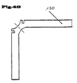
- a profile floor 144 is shown, which is formed as an aluminum profile in one-part or multi-part design. In the case of a multi-part design, the profiles are clipped together or pushed into one another. 60a, a profile floor 144 can be suspended via a correspondingly adapted corner connector 234. The free leg of the corner connector 234 can be inserted, for example, into a receiving opening 208 of a connecting element 16 according to FIGS. 35a and 35b for fastening the profile base 144.
- the base plate 144 is provided with a circumferential corner profile 146, the profile here being able to be designed as a frame and being connected to the base 144 by screws.
- the bottom 144 is formed from a folded sheet metal, the lateral folds serving for stiffening and being able to be circumferential. In a manner not shown here, the corners of the folds are welded for stiffening.
- the additional tab 146 provided in the middle on the underside of the bottom 144 can be connected to the bottom by welding or gluing.
- additional profiles can be made lengthways and / or crosswise be attached to the floor.
- further profiles 148 can also be inserted into the folds, as is explained in more detail using the embodiment according to FIG. 63. In the embodiments according to FIGS.
- the entire floor consists of a floor frame 150 and a support surface 144 which forms the base itself.
- the support surface 144 can now either be folded or placed on a provided tab.
- a further profile can be attached to the frame, as shown in FIG. 65, or the support surface of the floor can have a corresponding stiffening 146, as has already been explained with reference to FIG. 62.
- 61a, 61b and 61c show alternative embodiments of the fastening possibility of the base plate 144.
- a shelf support 147 is shown here, which can be used, for example, in an interruption of the function bar 50, as denoted by 75 in FIG. 40.
- a base 144 made of sheet steel, for example is at least partially bent over in the edge region, so that a connecting lug 145 is formed which can be screwed to a mounting plate 50 (not shown here) by means of corresponding screw holes.
- a base plate 144 which consists for example of sheet metal, is connected to a mounting plate 50 via an angled sheet metal edge 145.
- it can also be a base plate 144 made of any other material.
- FIG. 65 shows the bottom frame 150 according to the embodiment according to FIG. 65 in a top view.
- the floor frame can be non-detachably or releasably connected to one another.
- 67, 68 and 69 are corner connectors for the profiles of the floor frame 150 shown, which are designated 152, 154 and 156 here. These can be connected to each other with the floor profiles by means of a press fit or by screwing. Appropriate milling of the individual profile struts, as shown in FIG. 69, visually conceals the corner connection, ie the bottom is formed without a joint when viewed from the front.
- the corner connectors can be fastened to the connecting element 16 or to the mounting plate 50.
- a lattice frame floor 158 which, in a very simple embodiment, can be inserted into corresponding grooves of the connecting element 16 and fixed there.
- a trellis can be used, for example, as a so-called parking level, i.e. serve as a storage area below the worktop.
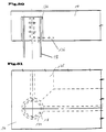
- FIG. 72 shows a floor in plan view, which has recesses 160 in the respective corner regions. In the built-in version, as shown in FIG. 71, these recesses lie against the projection formed by the mounting plate 50 and thus offer protection against inadvertent pulling out of the base 144. A corresponding embodiment without a mounting plate 50 is shown in FIG. 71a.
- FIGS. 74a, b and c prefabricated assemblies of floors, sides and rear wall elements are shown, which can be inserted into the basic structure 12 as integrated components.
- the elements are assembled from several parts with simple screw connections or spot welded.
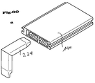
- the 75 shows an integrated side part 162 which integrally integrates two connecting elements 16 and one side part 44.
- the side part 44 is designed here as a hollow chamber aluminum profile to reduce weight.
- the integrated component 162 according to FIG. 75 is shown, in which a groove 164 is additionally provided, into which a mounting plate 50 can be inserted.
- FIG. 8 the embodiment according to FIG. 8 is taken up again, different arrangements of the kitchen cabinet front plate 166 being shown here.
- the kitchen cabinet front plate is arranged behind the center line of the hollow profile of the connecting element 16.
- a gap is possible between the connecting element 16 and the front plate.
- 78 shows an embodiment in which the kitchen front plate lies in front of the center line of the hollow profile of the connecting element 16.
- a gap is formed between the kitchen front plate 166 and the connecting element 16.
- FIG. 79 an arrangement according to FIG.
- a seal 168 is attached as a wiper seal made of elastic material or a brush, which in this exemplary embodiment is received and held in a groove of the connecting element and that Seals the interior of the kitchen furniture against dust, dirt, vermin or the like.
- a seal 170 is formed here as a stop seal made of elastic material or a brush, which is held or glued here in a groove in the mounting plate 50.
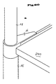
- 80a and 80b each show connecting elements 16, to which tubes 18 each attach. At the lower part there are foot parts and at the upper part tubes 18, as shown for example in Fig. 7a. In contrast to the design according to the embodiment according to FIG. 7a, a bottom 240 is inserted here into corresponding receiving slots of the connecting elements 16.
- an eccentric 250 is shown in dashed lines, which is integrated in the holder and is used for simple fastening.
Landscapes
- Engineering & Computer Science (AREA)
- General Engineering & Computer Science (AREA)
- Mechanical Engineering (AREA)
- Assembled Shelves (AREA)
- Combinations Of Kitchen Furniture (AREA)
- Furniture Connections (AREA)
Priority Applications (5)
| Application Number | Priority Date | Filing Date | Title |
|---|---|---|---|
| US08/877,943 US6000874A (en) | 1996-06-20 | 1997-06-18 | Furniture system, in particular a kitchen furniture system |
| KR1019970025759A KR100221866B1 (ko) | 1996-06-20 | 1997-06-19 | 주방용 가구 시스템 |
| TR97/00519A TR199700519A2 (xx) | 1996-06-20 | 1997-06-19 | Bir mobilya sistemi, özelde, bir mutfak mobilya sistemi. |
| BR9703651A BR9703651A (pt) | 1996-06-20 | 1997-06-20 | Sistema de móveis em particular um sistema de móveis de cozinha |
| US09/322,682 US6196753B1 (en) | 1996-06-20 | 1999-05-28 | Furniture system in particular a kitchen furniture system |
Applications Claiming Priority (2)
| Application Number | Priority Date | Filing Date | Title |
|---|---|---|---|
| DE19624673 | 1996-06-20 | ||
| DE19624673A DE19624673C1 (de) | 1996-06-20 | 1996-06-20 | Möbelsystem, insbesondere Küchenmöbelsystem |
Publications (3)
| Publication Number | Publication Date |
|---|---|
| EP0813832A2 true EP0813832A2 (fr) | 1997-12-29 |
| EP0813832A3 EP0813832A3 (fr) | 2002-01-02 |
| EP0813832B1 EP0813832B1 (fr) | 2004-07-28 |
Family
ID=7797506
Family Applications (1)
| Application Number | Title | Priority Date | Filing Date |
|---|---|---|---|
| EP97108219A Expired - Lifetime EP0813832B1 (fr) | 1996-06-20 | 1997-05-21 | Système de meubles, en particulier, système de meubles pour cuisines |
Country Status (5)
| Country | Link |
|---|---|
| EP (1) | EP0813832B1 (fr) |
| KR (1) | KR100221866B1 (fr) |
| AT (1) | ATE271809T1 (fr) |
| DE (2) | DE19624673C1 (fr) |
| ES (1) | ES2224195T3 (fr) |
Families Citing this family (7)
| Publication number | Priority date | Publication date | Assignee | Title |
|---|---|---|---|---|
| DE19738964A1 (de) * | 1997-09-05 | 1999-03-11 | Bulthaup Gmbh & Co | Spüle mit Spülbecken und Einhängebehälter |
| DE10011446B4 (de) * | 2000-03-10 | 2006-12-28 | Stefan Singer | Möbelsystem |
| DE10116098C2 (de) * | 2000-03-30 | 2003-12-24 | Rieber Gmbh & Co Kg | Küchensystem |
| DE10061778A1 (de) * | 2000-12-12 | 2002-07-11 | Aeg Hausgeraete Gmbh | Kühl- und/oder Gefriergerät für den Haushalt |
| KR100737425B1 (ko) | 2006-08-24 | 2007-07-09 | 위니아만도 주식회사 | 전자기기용 지지대 및 식품저장고 및 전자기기에 설치되는프레임 조립체 |
| ES2837409T3 (es) * | 2016-12-12 | 2021-06-30 | Ibk Project Srl | Kit para proporcionar cocinas modulares |
| DE102020126727A1 (de) | 2020-10-12 | 2022-04-14 | Westermann Kg | Aus vertikal und horizontal verlaufenden Profilteilen gebildetes Möbel, Einschubteil für ein aus Profilteilen gebildetes Möbel sowie Schublade für ein Möbel |
Family Cites Families (5)
| Publication number | Priority date | Publication date | Assignee | Title |
|---|---|---|---|---|
| US269907A (en) * | 1883-01-02 | Corner for picture-frames | ||
| US3851601A (en) * | 1973-02-09 | 1974-12-03 | J Davis | Display case stand |
| US4637324A (en) * | 1981-08-27 | 1987-01-20 | Janson Richard W | Furniture assembly and assembly device |
| JPS63169158U (fr) * | 1987-04-27 | 1988-11-02 | ||
| US4864795A (en) * | 1987-05-22 | 1989-09-12 | Uni Corp. | Structural framework system and clamp assembly |
-
1996
- 1996-06-20 DE DE19624673A patent/DE19624673C1/de not_active Expired - Fee Related
-
1997
- 1997-05-21 EP EP97108219A patent/EP0813832B1/fr not_active Expired - Lifetime
- 1997-05-21 DE DE59711800T patent/DE59711800D1/de not_active Expired - Fee Related
- 1997-05-21 AT AT97108219T patent/ATE271809T1/de not_active IP Right Cessation
- 1997-05-21 ES ES97108219T patent/ES2224195T3/es not_active Expired - Lifetime
- 1997-06-19 KR KR1019970025759A patent/KR100221866B1/ko not_active Expired - Fee Related
Also Published As
| Publication number | Publication date |
|---|---|
| DE59711800D1 (de) | 2004-09-02 |
| ES2224195T3 (es) | 2005-03-01 |
| DE19624673C1 (de) | 1997-07-24 |
| ATE271809T1 (de) | 2004-08-15 |
| EP0813832A3 (fr) | 2002-01-02 |
| KR980000269A (ko) | 1998-03-30 |
| EP0813832B1 (fr) | 2004-07-28 |
| KR100221866B1 (ko) | 1999-09-15 |
Similar Documents
| Publication | Publication Date | Title |
|---|---|---|
| DE102015109016B4 (de) | Einhängerahmen für Abfallbehälter in Möbelauszügen | |
| DE2201232C3 (de) | Verfahren zum Herstellen eines kastenartigen Gehäuses | |
| EP0813832A2 (fr) | Système de meubles, en particulier, système de meubles pour cuisines | |
| DE4420711A1 (de) | Duschabtrennung | |
| EP2801291A1 (fr) | Ferrure de meuble pour former un dispositif coulissant de collecte de déchets | |
| EP3981289A1 (fr) | Meuble formé à partir de pièces profilées verticales et horizontales, élément guide pour un meuble formé à partir de pièces profilées, ainsi que tiroir pour un meuble | |
| DE3231802C2 (fr) | ||
| DE9422457U1 (de) | Beschlag zur Befestigung einer Rückwand einer Schublade | |
| EP0441162A2 (fr) | Tiroir | |
| DE29611951U1 (de) | Traggestellrahmen | |
| WO2011131641A1 (fr) | Ensemble armoire encastré | |
| CH711428B1 (de) | Modulares System für Schränke und/oder Regale. | |
| DE102011015494B4 (de) | Befestigungsanordnung | |
| EP4324359B1 (fr) | Meuble bas et meuble sanitaire | |
| DE102014106539B4 (de) | Traverse für einen Schrank | |
| DE29714821U1 (de) | Küchenmöbelsystem in wangenbauweise, insbesondere zur un- und/oder bedingten Wandmontage | |
| AT409066B (de) | Möbel mit einem tragenden gestell | |
| DE202018103987U1 (de) | Möbelsystem zum Bau von unterschiedlichen Möbelarrangements | |
| AT1609U1 (de) | Verteilerschrank für sanitär- und/oder heizungsinstallationen | |
| DE20004358U1 (de) | Möbelsystem | |
| DE4430320C2 (de) | Möbelsystem für die Erstellung von Regalen, Schränken, Vitrinen und Tischen | |
| EP1000568A1 (fr) | Parois de placard pour construction de systèmes | |
| DE3224166A1 (de) | Eckverbindung zwischen einer vertikalen, profilierten saeule und einer horizontalen platte, vorzugsweise fuer tische, schraenke u. dgl. | |
| EP4335323A1 (fr) | Meuble sanitaire suspendu au mur | |
| DE6910098U (de) | Zerlegbare anbaukueche mit montagerahmen |
Legal Events
| Date | Code | Title | Description |
|---|---|---|---|
| PUAI | Public reference made under article 153(3) epc to a published international application that has entered the european phase |
Free format text: ORIGINAL CODE: 0009012 |
|
| AK | Designated contracting states |
Kind code of ref document: A2 Designated state(s): AT BE CH DE ES FR GB GR IT LI LU NL SE |
|
| PUAL | Search report despatched |
Free format text: ORIGINAL CODE: 0009013 |
|
| AK | Designated contracting states |
Kind code of ref document: A3 Designated state(s): AT BE CH DE ES FR GB GR IT LI LU NL SE |
|
| 17P | Request for examination filed |
Effective date: 20020214 |
|
| 17Q | First examination report despatched |
Effective date: 20020610 |
|
| GRAP | Despatch of communication of intention to grant a patent |
Free format text: ORIGINAL CODE: EPIDOSNIGR1 |
|
| GRAS | Grant fee paid |
Free format text: ORIGINAL CODE: EPIDOSNIGR3 |
|
| RAP1 | Party data changed (applicant data changed or rights of an application transferred) |
Owner name: BULTHAUP GMBH & CO. KG |
|
| GRAA | (expected) grant |
Free format text: ORIGINAL CODE: 0009210 |
|
| AK | Designated contracting states |
Kind code of ref document: B1 Designated state(s): AT BE CH DE ES FR GB GR IT LI LU NL SE |
|
| REG | Reference to a national code |
Ref country code: GB Ref legal event code: FG4D Free format text: NOT ENGLISH |
|
| REG | Reference to a national code |
Ref country code: CH Ref legal event code: NV Representative=s name: BOVARD AG PATENTANWAELTE Ref country code: CH Ref legal event code: EP |
|
| REF | Corresponds to: |
Ref document number: 59711800 Country of ref document: DE Date of ref document: 20040902 Kind code of ref document: P |
|
| PG25 | Lapsed in a contracting state [announced via postgrant information from national office to epo] |
Ref country code: SE Free format text: LAPSE BECAUSE OF FAILURE TO SUBMIT A TRANSLATION OF THE DESCRIPTION OR TO PAY THE FEE WITHIN THE PRESCRIBED TIME-LIMIT Effective date: 20041028 Ref country code: GR Free format text: LAPSE BECAUSE OF FAILURE TO SUBMIT A TRANSLATION OF THE DESCRIPTION OR TO PAY THE FEE WITHIN THE PRESCRIBED TIME-LIMIT Effective date: 20041028 |
|
| GBT | Gb: translation of ep patent filed (gb section 77(6)(a)/1977) |
Effective date: 20041104 |
|
| REG | Reference to a national code |
Ref country code: ES Ref legal event code: FG2A Ref document number: 2224195 Country of ref document: ES Kind code of ref document: T3 |
|
| ET | Fr: translation filed | ||
| PG25 | Lapsed in a contracting state [announced via postgrant information from national office to epo] |
Ref country code: LU Free format text: LAPSE BECAUSE OF NON-PAYMENT OF DUE FEES Effective date: 20050521 |
|
| PLBE | No opposition filed within time limit |
Free format text: ORIGINAL CODE: 0009261 |
|
| STAA | Information on the status of an ep patent application or granted ep patent |
Free format text: STATUS: NO OPPOSITION FILED WITHIN TIME LIMIT |
|
| 26N | No opposition filed |
Effective date: 20050429 |
|
| PGFP | Annual fee paid to national office [announced via postgrant information from national office to epo] |
Ref country code: ES Payment date: 20080522 Year of fee payment: 12 Ref country code: DE Payment date: 20080530 Year of fee payment: 12 Ref country code: CH Payment date: 20080526 Year of fee payment: 12 |
|
| PGFP | Annual fee paid to national office [announced via postgrant information from national office to epo] |
Ref country code: AT Payment date: 20080521 Year of fee payment: 12 |
|
| PGFP | Annual fee paid to national office [announced via postgrant information from national office to epo] |
Ref country code: BE Payment date: 20080526 Year of fee payment: 12 Ref country code: IT Payment date: 20080521 Year of fee payment: 12 |
|
| PGFP | Annual fee paid to national office [announced via postgrant information from national office to epo] |
Ref country code: NL Payment date: 20080528 Year of fee payment: 12 |
|
| PGFP | Annual fee paid to national office [announced via postgrant information from national office to epo] |
Ref country code: FR Payment date: 20080521 Year of fee payment: 12 |
|
| PGFP | Annual fee paid to national office [announced via postgrant information from national office to epo] |
Ref country code: GB Payment date: 20080520 Year of fee payment: 12 |
|
| BERE | Be: lapsed |
Owner name: *BULTHAUP G.M.B.H. & CO. K.G. Effective date: 20090531 |
|
| REG | Reference to a national code |
Ref country code: CH Ref legal event code: PL |
|
| GBPC | Gb: european patent ceased through non-payment of renewal fee |
Effective date: 20090521 |
|
| PG25 | Lapsed in a contracting state [announced via postgrant information from national office to epo] |
Ref country code: LI Free format text: LAPSE BECAUSE OF NON-PAYMENT OF DUE FEES Effective date: 20090531 Ref country code: CH Free format text: LAPSE BECAUSE OF NON-PAYMENT OF DUE FEES Effective date: 20090531 Ref country code: AT Free format text: LAPSE BECAUSE OF NON-PAYMENT OF DUE FEES Effective date: 20090521 |
|
| NLV4 | Nl: lapsed or anulled due to non-payment of the annual fee |
Effective date: 20091201 |
|
| PG25 | Lapsed in a contracting state [announced via postgrant information from national office to epo] |
Ref country code: NL Free format text: LAPSE BECAUSE OF NON-PAYMENT OF DUE FEES Effective date: 20091201 |
|
| REG | Reference to a national code |
Ref country code: FR Ref legal event code: ST Effective date: 20100129 |
|
| PG25 | Lapsed in a contracting state [announced via postgrant information from national office to epo] |
Ref country code: FR Free format text: LAPSE BECAUSE OF NON-PAYMENT OF DUE FEES Effective date: 20090602 |
|
| PG25 | Lapsed in a contracting state [announced via postgrant information from national office to epo] |
Ref country code: GB Free format text: LAPSE BECAUSE OF NON-PAYMENT OF DUE FEES Effective date: 20090521 |
|
| PG25 | Lapsed in a contracting state [announced via postgrant information from national office to epo] |
Ref country code: DE Free format text: LAPSE BECAUSE OF NON-PAYMENT OF DUE FEES Effective date: 20091201 Ref country code: BE Free format text: LAPSE BECAUSE OF NON-PAYMENT OF DUE FEES Effective date: 20090531 |
|
| REG | Reference to a national code |
Ref country code: ES Ref legal event code: FD2A Effective date: 20090522 |
|
| PG25 | Lapsed in a contracting state [announced via postgrant information from national office to epo] |
Ref country code: ES Free format text: LAPSE BECAUSE OF NON-PAYMENT OF DUE FEES Effective date: 20090522 |
|
| PG25 | Lapsed in a contracting state [announced via postgrant information from national office to epo] |
Ref country code: IT Free format text: LAPSE BECAUSE OF NON-PAYMENT OF DUE FEES Effective date: 20090521 |