EP0813932B1 - Dispositif de polissage muni d'une cassette avec toile - Google Patents
Dispositif de polissage muni d'une cassette avec toile Download PDFInfo
- Publication number
- EP0813932B1 EP0813932B1 EP97110228A EP97110228A EP0813932B1 EP 0813932 B1 EP0813932 B1 EP 0813932B1 EP 97110228 A EP97110228 A EP 97110228A EP 97110228 A EP97110228 A EP 97110228A EP 0813932 B1 EP0813932 B1 EP 0813932B1
- Authority
- EP
- European Patent Office
- Prior art keywords
- cloth
- cartridge
- polishing
- base member
- turntable
- Prior art date
- Legal status (The legal status is an assumption and is not a legal conclusion. Google has not performed a legal analysis and makes no representation as to the accuracy of the status listed.)
- Expired - Lifetime
Links
Images

Classifications
-
- B—PERFORMING OPERATIONS; TRANSPORTING
- B24—GRINDING; POLISHING
- B24B—MACHINES, DEVICES, OR PROCESSES FOR GRINDING OR POLISHING; DRESSING OR CONDITIONING OF ABRADING SURFACES; FEEDING OF GRINDING, POLISHING, OR LAPPING AGENTS
- B24B37/00—Lapping machines or devices; Accessories
- B24B37/11—Lapping tools
- B24B37/20—Lapping pads for working plane surfaces
- B24B37/26—Lapping pads for working plane surfaces characterised by the shape of the lapping pad surface, e.g. grooved
-
- H—ELECTRICITY
- H10—SEMICONDUCTOR DEVICES; ELECTRIC SOLID-STATE DEVICES NOT OTHERWISE PROVIDED FOR
- H10P—GENERIC PROCESSES OR APPARATUS FOR THE MANUFACTURE OR TREATMENT OF DEVICES COVERED BY CLASS H10
- H10P52/00—Grinding, lapping or polishing of wafers, substrates or parts of devices
-
- B—PERFORMING OPERATIONS; TRANSPORTING
- B24—GRINDING; POLISHING
- B24B—MACHINES, DEVICES, OR PROCESSES FOR GRINDING OR POLISHING; DRESSING OR CONDITIONING OF ABRADING SURFACES; FEEDING OF GRINDING, POLISHING, OR LAPPING AGENTS
- B24B37/00—Lapping machines or devices; Accessories
- B24B37/11—Lapping tools
- B24B37/12—Lapping plates for working plane surfaces
-
- B—PERFORMING OPERATIONS; TRANSPORTING
- B24—GRINDING; POLISHING
- B24B—MACHINES, DEVICES, OR PROCESSES FOR GRINDING OR POLISHING; DRESSING OR CONDITIONING OF ABRADING SURFACES; FEEDING OF GRINDING, POLISHING, OR LAPPING AGENTS
- B24B37/00—Lapping machines or devices; Accessories
- B24B37/11—Lapping tools
- B24B37/20—Lapping pads for working plane surfaces
Definitions
- the present invention relates to a polishing apparatus for polishing a workpiece such as a semiconductor wafer, and more particularly to a polishing apparatus having a cloth cartridge which is detachably exchangeably mounted on a turntable.
- CMP Chemical Mechanical Polishing
- a polishing apparatus has a turntable and a top ring which rotate at respective individual speeds.
- a polishing cloth is attached to the upper surface of the turntable.
- a semiconductor wafer to be polished is placed on the polishing cloth and clamped between the top ring and the turntable.
- An abrasive liquid containing abrasive grains is supplied onto the polishing cloth and retained on the polishing cloth.
- the top ring exerts a certain pressure on the turntable, and the surface of the semiconductor wafer held against the polishing cloth is therefore polished by a combination of chemical polishing and mechanical polishing to a flat mirror finish while the top ring and the turntable are rotated.
- the polishing cloth is processed to recover its original polishing capability.
- Various processes have been and are being developed for restoring the polishing cloth, and are collectively called "dressing".
- the polishing cloth is dressed by a dressing tool in order to enable the polishing apparatus to perform a good polishing function at all times without undesired degradation of a polishing performance.
- polishing apparatus When replacing the polishing cloth, the polishing apparatus is shut down, and the polishing cloth is detached from the turntable. Thereafter, an abrasive liquid remaining on the turntable is washed out, and a new polishing cloth is attached to the turntable after drying the turntable.
- This maintenance work is troublesome and requires a long period of time during which the polishing apparatus continues to be shut down, thus lowering the productivity of the semiconductor devices per unit time.
- the conventional cloth cartridge has a relatively large outer diameter and is difficult to be handled.
- the cloth cartridge normally has a diameter of 600mm or more, and hence the replacement of the cloth cartridge involves removal of a disk-shaped object having a diameter of 600mm or more from the polishing apparatus.
- the polishing apparatus is installed in a clean room, and when the cloth cartridge is replaced, the polishing cloth is normally wet with an abrasive liquid and such condition of the polishing cloth is not suitable for environment of the clean room.
- the cloth cartridge is packed in a bag or wrapped by a sheet inside the polishing apparatus, and then the packed or wrapped cloth cartridge is taken out from the polishing apparatus.
- handling of the cloth cartridge is troublesome and the replacement work is time-consuming.
- Polishing apparatus and, respectively, cloth cartridges according to the preambles of claims 1, 5, 9 and 10 are known, for example, from DE-A-195 38 991.
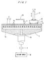
- a polishing apparatus according to an embodiment of the present invention will be described below with reference to FIGS. 1 through 2B.
- a polishing apparatus comprises a turntable 1, a cloth cartridge 2 detachably exchangeably mounted on the turntable 1, and a top ring 6 for holding a semiconductor wafer 5 as a workpiece and pressing the semiconductor wafer 5 against the turntable 1.
- the cloth cartridge 2 comprises a disk-shaped base plate 3 and a polishing cloth 4 bonded to an upper surface of the base plate 3.
- the base plate 3 constitutes a cartridge base member.
- the turntable 1 has a chamber la therein, and a number of vertical suction holes 1b which are open at the upper surface of the turntable 1 and communicate with the chamber 1a.
- the chamber la communicates with a vacuum source 8 through a vertical hole 1c formed in the turntable 1 and a rotary joint 7 coupled to a shaft of the turntable 1. Therefore, the cloth cartridge 2 can be fixedly mounted on the turntable 1 under vacuum developed by the vacuum source 8 when the suction holes 1b communicate with the vacuum source 8.
- the cloth cartridge 2 can be detached from the turntable 1 when vacuum in the suction holes 1b is broken, i.e., the pressure in the suction holes 1b is raised to ambient.
- the base plate 3 of the cloth cartridge 2 is made of alloy steel such as stainless steel, aluminum or plastics as a main component.
- the polishing cloth 4 of the cloth cartridge 2 is a commercially available polishing cloth which is normally used to polish semiconductor wafers. Examples of the polishing cloth are Suba 800 and IC-1000 manufactured by Rodel Products Corporation and Surfin xxx-5 and Surfin 000 manufactured by Fujimi Inc.
- the polishing cloth sold under the trade names Suba 800, Surfin xxx-5, and Surfin 000 is made of non-woven fabric composed of fibers bound together by urethane resin, and the polishing cloth sold under the trade name IC-1000 is made of polyurethane foam which is porous and has minute recesses or micropores in its surface.
- the turntable 1 is rotatable about its own axis as indicated by an arrow by a motor (not shown) which is coupled to the turntable 1.
- the top ring 6 is coupled to a motor (not shown) and also to a lifting/lowering cylinder (not shown).
- the top ring 6 is vertically movable and rotatable about its own axis, as indicated by the arrows, by the motor and the lifting/lowering cylinder.
- the top ring 6 can therefore press the semiconductor wafer 5 against the polishing cloth 4 under a desired pressure.
- the semiconductor wafer 5 is attached to a lower surface of the top ring 6 under a vacuum or the like.
- a guide ring 9 is mounted on the outer circumferential edge of the lower surface of the top ring 6 for preventing the semiconductor wafer 5 from being disengaged from the top ring 6.
- An abrasive liquid Q is supplied through a supply pipe 10 onto the polishing cloth 4.
- FIGS. 2A and 2B show the detailed structure of the cloth cartridge 2 shown in FIG. 1.
- the cloth cartridge 2 is divided into four segments.
- the base plate 3 comprises four sectorial base plate segments 3A, 3B, 3C and 3D
- the polishing cloth 4 comprises four sectorial polishing cloth segments 4A, 4B, 4C and 4D.
- each unit comprises one of the base plate segments 3A, 3B, 3C and 3D and one of the polishing cloth segments 4A, 4B, 4C and 4D bonded to one of the base plate segments 4A, 4B, 4C and 4D.
- the division-type cloth cartridge 2 is detachably mounted on the upper surface of the turntable 1 under vacuum.
- the cloth cartridge 2 can be fixedly mounted on the turntable 1 or detached from the turntable 1 by an individual unit comprising one of the base plate segments 3A, 3B, 3C and 3D and one of the polishing cloth segments 4A, 4B, 4C and 4D.
- This structure of the cloth cartridge 2 allows the replacement work of the cloth cartridge 2 to be easy, and further allows the size of the bag for containing the cloth cartridge to be small.
- a bag having dimensions of 600mm x 600mm or larger is required for containing the conventional cloth cartridge therein.
- a bag having dimensions of 300mm x 300mm is sufficient for containing the cloth cartridge 2 therein.
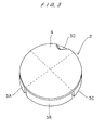
- FIG. 3 shows a cloth cartridge in a polishing apparatus according to another embodiment of the present invention.
- the cloth cartridge comprises four sectorial base plate segments 3A, 3B, 3C and 3D, and a circular sheet of polishing cloth 4 bonded to the upper surfaces of the base plate segments 3A, 3B, 3C and 3D.
- the cloth cartridge 2 of this embodiment when replaced, can be folded along dotted lines in half or fourth. That is, the cloth cartridge 2 can be folded into a more compact form by utilizing flexibility of the polishing cloth 4. Therefore, the cloth cartridge of this embodiment can be easily handled, and can be contained in a small-sized bag as in the embodiment of FIG. 2.
- the cloth cartridge comprises a plurality of base plate segments and a polishing cloth bonded to the upper surfaces of the base plate segments, and can be folded by utilizing flexibility of the polishing cloth.
- the polishing cloth may comprise a plurality of polishing cloth segments, and a connector such as a hinge may be provided between two base plate segments adjacent to each other so that the cloth cartridge can be folded in half or fourth.
- a connector such as a hinge
- the cloth cartridge may be handled by an individual unit comprising a base plate segment and a polishing cloth segment without folding, as described in the first embodiment.
- the cloth cartridge can be separated into a plurality of units or can be folded into a more compact form, the cloth cartridge can be easily handled at the time of replacement, and pollution of the environment of the clean room in which the polishing apparatus is installed can be prevented.
Landscapes
- Engineering & Computer Science (AREA)
- Mechanical Engineering (AREA)
- Finish Polishing, Edge Sharpening, And Grinding By Specific Grinding Devices (AREA)
- Mechanical Treatment Of Semiconductor (AREA)
- Polishing Bodies And Polishing Tools (AREA)
Claims (10)
- Dispositif de polissage destiné à polir une surface d'une pièce à usiner, comportant :caractérisé en ce que ledit élément formant base de cartouche comporte une pluralité de segments d'élément de base, et ledit tissu de polissage comporte une pluralité de segments de tissu de polissage collés sur les surfaces supérieures desdits segments d'élément de base, respectivement.un plateau tournant,une cartouche de tissu montée de manière amovible et de manière remplaçable sur ledit plateau tournant, ladite cartouche de tissu comportant un élément formant base de cartouche et un tissu de polissage collé sur une surface supérieure dudit élément formant base de cartouche, etun anneau supérieur destiné à maintenir et à comprimer ladite pièce à usiner contre ledit tissu de polissage,
- Dispositif de polissage selon la revendication 1, dans lequel ladite cartouche de tissu est montée de manière fixe sur ledit plateau tournant, sous vide.
- Dispositif de polissage selon la revendication 1, dans lequel ledit élément formant base de cartouche est constitué d'un élément parmi un acier allié, l'aluminium, et des matières plastiques en tant que composant principal.
- Dispositif de polissage selon la revendication 1, dans lequel ladite cartouche de tissu est manipulée par une unité individuelle comportant un desdits segments d'élément formant base et un desdits segments de tissu de polissage lors du remplacement de ladite cartouche de tissu.
- Dispositif de polissage destiné à polir une surface d'une pièce à usiner, comportant :caractérisé en ce que ledit élément formant base de cartouche comporte une pluralité de segments d'élément formant base, et ledit tissu de polissage comporte une feuille de tissu de polissage collée sur les surfaces supérieures desdits segments d'élément formant base.un plateau tournant,une cartouche de tissu montée de manière amovible et de manière remplaçable sur ledit plateau tournant, ladite cartouche de tissu comportant un élément formant base de cartouche et un tissu de polissage collé sur une surface supérieure dudit élément formant base de cartouche, etun anneau supérieur destiné à maintenir et à comprimer ladite pièce à usiner contre ledit tissu de polissage,
- Dispositif de polissage selon la revendication 5, dans lequel ladite cartouche de tissu est montée de manière fixe sur ledit plateau tournant, sous vide.
- Dispositif de polissage selon la revendication 5, dans lequel ledit élément formant base de cartouche est constitué d'un élément parmi un acier allié, l'aluminium, et des matières plastiques en tant que composant principal.
- Dispositif de polissage selon la revendication 5, dans lequel ladite cartouche de tissu est manipulée en pliant ladite cartouche de tissu sous une forme plus compacte en utilisant la souplesse dudit tissu de polissage.
- Cartouche de tissu devant être montée de manière amovible et de manière remplaçable sur un plateau tournant d'un dispositif de polissage destiné à être utilisé pour polir une surface d'une pièce à usiner, ladite cartouche de tissu comportant :caractérisée en ce que ledit élément formant base de cartouche comporte une pluralité de segments d'élément formant base, et ledit tissu de polissage comporte une pluralité de segments de tissu de polissage collés sur les surfaces supérieures desdits segments d'élément formant base, respectivement.un élément formant base de cartouche, etun tissu de polissage collé sur une surface supérieure dudit élément formant base de cartouche,
- Cartouche de tissu devant être montée de manière amovible et de manière remplaçable sur un plateau tournant d'un dispositif de polissage destiné à être utilisé pour polir une surface d'une pièce à usiner, ladite cartouche de tissu comportant :caractérisée en ce que ledit élément formant base de cartouche comporte une pluralité de segments d'élément de base, et ledit tissu de polissage comporte une feuille de tissu de polissage collée sur les surfaces supérieures desdits segments d'élément formant base.un élément formant base de cartouche, etun tissu de polissage collé sur une surface supérieure dudit élément formant base de cartouche,
Applications Claiming Priority (3)
| Application Number | Priority Date | Filing Date | Title |
|---|---|---|---|
| JP18147196 | 1996-06-21 | ||
| JP18147196A JP3611404B2 (ja) | 1996-06-21 | 1996-06-21 | ポリッシング装置 |
| JP181471/96 | 1996-06-21 |
Publications (2)
| Publication Number | Publication Date |
|---|---|
| EP0813932A1 EP0813932A1 (fr) | 1997-12-29 |
| EP0813932B1 true EP0813932B1 (fr) | 2001-10-24 |
Family
ID=16101344
Family Applications (1)
| Application Number | Title | Priority Date | Filing Date |
|---|---|---|---|
| EP97110228A Expired - Lifetime EP0813932B1 (fr) | 1996-06-21 | 1997-06-23 | Dispositif de polissage muni d'une cassette avec toile |
Country Status (5)
| Country | Link |
|---|---|
| US (1) | US5921852A (fr) |
| EP (1) | EP0813932B1 (fr) |
| JP (1) | JP3611404B2 (fr) |
| KR (1) | KR100435303B1 (fr) |
| DE (1) | DE69707565T2 (fr) |
Families Citing this family (20)
| Publication number | Priority date | Publication date | Assignee | Title |
|---|---|---|---|---|
| WO1999028083A1 (fr) * | 1997-12-03 | 1999-06-10 | Speedfam-Ipec Corporation | Tampon a polir en secteurs |
| JP2000094307A (ja) | 1998-09-18 | 2000-04-04 | Ebara Corp | ポリッシング装置 |
| US6602380B1 (en) * | 1998-10-28 | 2003-08-05 | Micron Technology, Inc. | Method and apparatus for releasably attaching a polishing pad to a chemical-mechanical planarization machine |
| US6491570B1 (en) * | 1999-02-25 | 2002-12-10 | Applied Materials, Inc. | Polishing media stabilizer |
| US6217426B1 (en) * | 1999-04-06 | 2001-04-17 | Applied Materials, Inc. | CMP polishing pad |
| DE19939258A1 (de) * | 1999-08-19 | 2001-03-08 | Wacker Siltronic Halbleitermat | Werkzeug und Verfahren zum abrasiven Bearbeiten einer im wesentlichen ebenen Fläche |
| US6302775B1 (en) * | 2000-03-22 | 2001-10-16 | Motorola, Inc. | Apparatus and method for cold cross-sectioning of soft materials |
| US6561884B1 (en) * | 2000-08-29 | 2003-05-13 | Applied Materials, Inc. | Web lift system for chemical mechanical planarization |
| US7077733B1 (en) * | 2000-08-31 | 2006-07-18 | Micron Technology, Inc. | Subpad support with a releasable subpad securing element and polishing apparatus including the subpad support |
| US6592439B1 (en) | 2000-11-10 | 2003-07-15 | Applied Materials, Inc. | Platen for retaining polishing material |
| US8062098B2 (en) * | 2000-11-17 | 2011-11-22 | Duescher Wayne O | High speed flat lapping platen |
| US6503131B1 (en) | 2001-08-16 | 2003-01-07 | Applied Materials, Inc. | Integrated platen assembly for a chemical mechanical planarization system |
| KR20030062133A (ko) * | 2002-01-16 | 2003-07-23 | 삼성전자주식회사 | 이동 통신 시스템의 기지국 송신 장치 |
| JP2006520273A (ja) * | 2003-03-14 | 2006-09-07 | 株式会社荏原製作所 | 研磨工具および研磨装置 |
| JP2004330326A (ja) * | 2003-05-02 | 2004-11-25 | Ebara Corp | ポリッシング装置 |
| KR100643495B1 (ko) * | 2004-11-16 | 2006-11-10 | 삼성전자주식회사 | 반도체 웨이퍼 폴리싱장치의 플래튼 구조 및 그 플래튼에고정되는 폴리싱패드 교체방법 |
| JP5009101B2 (ja) * | 2006-10-06 | 2012-08-22 | 株式会社荏原製作所 | 基板研磨装置 |
| US9102034B2 (en) * | 2013-08-30 | 2015-08-11 | Rohm And Haas Electronic Materials Cmp Holdings, Inc. | Method of chemical mechanical polishing a substrate |
| KR102406293B1 (ko) * | 2020-08-11 | 2022-06-10 | 에스씨플랫 주식회사 | 디스플레이 장치의 기판용 연마장비 |
| JP7870135B2 (ja) * | 2022-09-21 | 2026-06-04 | 株式会社Screenホールディングス | 下面ブラシ、ブラシユニットおよび基板洗浄装置 |
Family Cites Families (9)
| Publication number | Priority date | Publication date | Assignee | Title |
|---|---|---|---|---|
| GB1466545A (en) * | 1974-03-26 | 1977-03-09 | Nederman B | Abrasive disc |
| US4350497A (en) * | 1980-09-08 | 1982-09-21 | Abraham Ogman | Reinforced grinding device |
| US4527358A (en) * | 1983-08-29 | 1985-07-09 | General Signal Corporation | Removable polishing pad assembly |
| JPS60242975A (ja) * | 1984-05-14 | 1985-12-02 | Kanebo Ltd | 平面研磨装置 |
| JP2985490B2 (ja) * | 1992-02-28 | 1999-11-29 | 信越半導体株式会社 | 研磨機の除熱方法 |
| JPH07328915A (ja) * | 1994-06-03 | 1995-12-19 | Ebara Corp | ポリッシング装置 |
| EP0728055A1 (fr) * | 1994-09-08 | 1996-08-28 | Struers A/S | Feuille de couverture de meulage/polissage se pla ant sur un disque tournant de meulage/polissage |
| US5575707A (en) * | 1994-10-11 | 1996-11-19 | Ontrak Systems, Inc. | Polishing pad cluster for polishing a semiconductor wafer |
| JP3418467B2 (ja) * | 1994-10-19 | 2003-06-23 | 株式会社荏原製作所 | ポリッシング装置 |
-
1996
- 1996-06-21 JP JP18147196A patent/JP3611404B2/ja not_active Expired - Fee Related
-
1997
- 1997-06-20 KR KR1019970025990A patent/KR100435303B1/ko not_active Expired - Fee Related
- 1997-06-23 US US08/880,639 patent/US5921852A/en not_active Expired - Fee Related
- 1997-06-23 EP EP97110228A patent/EP0813932B1/fr not_active Expired - Lifetime
- 1997-06-23 DE DE69707565T patent/DE69707565T2/de not_active Expired - Lifetime
Also Published As
| Publication number | Publication date |
|---|---|
| JP3611404B2 (ja) | 2005-01-19 |
| US5921852A (en) | 1999-07-13 |
| EP0813932A1 (fr) | 1997-12-29 |
| JPH106209A (ja) | 1998-01-13 |
| DE69707565T2 (de) | 2002-07-11 |
| KR980005775A (ko) | 1998-03-30 |
| DE69707565D1 (de) | 2001-11-29 |
| KR100435303B1 (ko) | 2004-10-22 |
Similar Documents
| Publication | Publication Date | Title |
|---|---|---|
| US5921852A (en) | Polishing apparatus having a cloth cartridge | |
| US5651725A (en) | Apparatus and method for polishing workpiece | |
| KR100428881B1 (ko) | 폴리싱포의폴리싱표면의드레싱방법및드레싱장치 | |
| EP1250215B1 (fr) | Appareil et technique permettant de maitriser le polissage et la planarisation de tranches de semi-conducteur | |
| US6458012B1 (en) | Polishing apparatus | |
| US5902173A (en) | Polishing machine with efficient polishing and dressing | |
| US7104875B2 (en) | Chemical mechanical polishing apparatus with rotating belt | |
| US5921855A (en) | Polishing pad having a grooved pattern for use in a chemical mechanical polishing system | |
| US6152806A (en) | Concentric platens | |
| JP2004517479A (ja) | 表面積を減じた研磨パッドと可変式部分的パッド−ウェーハ・オーバラップ技法を用いて半導体ウェーハを研磨し平坦化するためのシステム及び方法 | |
| TWI423316B (zh) | 研磨方法及研磨裝置、及研磨裝置控制用程式 | |
| EP0818272A1 (fr) | Rétention d'un tampon de polissage sur un plateau dans un système de polissage mécano-chimique | |
| US5895270A (en) | Chemical mechanical polishing method and apparatus | |
| EP0842738B1 (fr) | Procédé et dispositif pour polir et nettoyer des pièces planes | |
| EP1025955B1 (fr) | Polissage mécano-chimique avec une toile de polissage mobile | |
| US7229343B2 (en) | Orbiting indexable belt polishing station for chemical mechanical polishing | |
| US6398626B1 (en) | Polishing apparatus | |
| EP1157783B1 (fr) | Procédé et dispositif de polissage | |
| EP0796702B1 (fr) | Appareil et procédé de polissage | |
| WO1999026761A1 (fr) | Appareil de polissage | |
| EP0806267A1 (fr) | Patin de polissage haché pour polir un substrat dans un système de polissage chemico-mécanique | |
| JPH0236066A (ja) | 研磨布および研磨装置 | |
| EP0769350A1 (fr) | Procédé et dispositif pour dresser un tissu de polissage |
Legal Events
| Date | Code | Title | Description |
|---|---|---|---|
| PUAI | Public reference made under article 153(3) epc to a published international application that has entered the european phase |
Free format text: ORIGINAL CODE: 0009012 |
|
| AK | Designated contracting states |
Kind code of ref document: A1 Designated state(s): DE FR |
|
| 17P | Request for examination filed |
Effective date: 19980629 |
|
| AKX | Designation fees paid |
Free format text: DE FR |
|
| RBV | Designated contracting states (corrected) |
Designated state(s): DE FR |
|
| GRAG | Despatch of communication of intention to grant |
Free format text: ORIGINAL CODE: EPIDOS AGRA |
|
| 17Q | First examination report despatched |
Effective date: 20010125 |
|
| GRAG | Despatch of communication of intention to grant |
Free format text: ORIGINAL CODE: EPIDOS AGRA |
|
| GRAH | Despatch of communication of intention to grant a patent |
Free format text: ORIGINAL CODE: EPIDOS IGRA |
|
| GRAH | Despatch of communication of intention to grant a patent |
Free format text: ORIGINAL CODE: EPIDOS IGRA |
|
| GRAA | (expected) grant |
Free format text: ORIGINAL CODE: 0009210 |
|
| AK | Designated contracting states |
Kind code of ref document: B1 Designated state(s): DE FR |
|
| REF | Corresponds to: |
Ref document number: 69707565 Country of ref document: DE Date of ref document: 20011129 |
|
| ET | Fr: translation filed | ||
| PLBE | No opposition filed within time limit |
Free format text: ORIGINAL CODE: 0009261 |
|
| STAA | Information on the status of an ep patent application or granted ep patent |
Free format text: STATUS: NO OPPOSITION FILED WITHIN TIME LIMIT |
|
| 26N | No opposition filed | ||
| PGFP | Annual fee paid to national office [announced via postgrant information from national office to epo] |
Ref country code: FR Payment date: 20080617 Year of fee payment: 12 |
|
| REG | Reference to a national code |
Ref country code: FR Ref legal event code: ST Effective date: 20100226 |
|
| PG25 | Lapsed in a contracting state [announced via postgrant information from national office to epo] |
Ref country code: FR Free format text: LAPSE BECAUSE OF NON-PAYMENT OF DUE FEES Effective date: 20090630 |
|
| PGFP | Annual fee paid to national office [announced via postgrant information from national office to epo] |
Ref country code: DE Payment date: 20100616 Year of fee payment: 14 |
|
| REG | Reference to a national code |
Ref country code: DE Ref legal event code: R119 Ref document number: 69707565 Country of ref document: DE Effective date: 20120103 |
|
| PG25 | Lapsed in a contracting state [announced via postgrant information from national office to epo] |
Ref country code: DE Free format text: LAPSE BECAUSE OF NON-PAYMENT OF DUE FEES Effective date: 20120103 |