EP0813941A2 - Machine-outil pour l'usinage de pièces allongées - Google Patents
Machine-outil pour l'usinage de pièces allongées Download PDFInfo
- Publication number
- EP0813941A2 EP0813941A2 EP97109751A EP97109751A EP0813941A2 EP 0813941 A2 EP0813941 A2 EP 0813941A2 EP 97109751 A EP97109751 A EP 97109751A EP 97109751 A EP97109751 A EP 97109751A EP 0813941 A2 EP0813941 A2 EP 0813941A2
- Authority
- EP
- European Patent Office
- Prior art keywords
- tool spindle
- machine according
- spindle
- workpiece
- joinery
- Prior art date
- Legal status (The legal status is an assumption and is not a legal conclusion. Google has not performed a legal analysis and makes no representation as to the accuracy of the status listed.)
- Granted
Links
Images
Classifications
-
- B—PERFORMING OPERATIONS; TRANSPORTING
- B27—WORKING OR PRESERVING WOOD OR SIMILAR MATERIAL; NAILING OR STAPLING MACHINES IN GENERAL
- B27M—WORKING OF WOOD NOT PROVIDED FOR IN SUBCLASSES B27B - B27L; MANUFACTURE OF SPECIFIC WOODEN ARTICLES
- B27M1/00—Working of wood not provided for in subclasses B27B - B27L, e.g. by stretching
- B27M1/08—Working of wood not provided for in subclasses B27B - B27L, e.g. by stretching by multi-step processes
-
- B—PERFORMING OPERATIONS; TRANSPORTING
- B23—MACHINE TOOLS; METAL-WORKING NOT OTHERWISE PROVIDED FOR
- B23Q—DETAILS, COMPONENTS, OR ACCESSORIES FOR MACHINE TOOLS, e.g. ARRANGEMENTS FOR COPYING OR CONTROLLING; MACHINE TOOLS IN GENERAL CHARACTERISED BY THE CONSTRUCTION OF PARTICULAR DETAILS OR COMPONENTS; COMBINATIONS OR ASSOCIATIONS OF METAL-WORKING MACHINES, NOT DIRECTED TO A PARTICULAR RESULT
- B23Q7/00—Arrangements for handling work specially combined with or arranged in, or specially adapted for use in connection with, machine tools, e.g. for conveying, loading, positioning, discharging, sorting
- B23Q7/06—Arrangements for handling work specially combined with or arranged in, or specially adapted for use in connection with, machine tools, e.g. for conveying, loading, positioning, discharging, sorting by means of pushers
-
- B—PERFORMING OPERATIONS; TRANSPORTING
- B23—MACHINE TOOLS; METAL-WORKING NOT OTHERWISE PROVIDED FOR
- B23Q—DETAILS, COMPONENTS, OR ACCESSORIES FOR MACHINE TOOLS, e.g. ARRANGEMENTS FOR COPYING OR CONTROLLING; MACHINE TOOLS IN GENERAL CHARACTERISED BY THE CONSTRUCTION OF PARTICULAR DETAILS OR COMPONENTS; COMBINATIONS OR ASSOCIATIONS OF METAL-WORKING MACHINES, NOT DIRECTED TO A PARTICULAR RESULT
- B23Q7/00—Arrangements for handling work specially combined with or arranged in, or specially adapted for use in connection with, machine tools, e.g. for conveying, loading, positioning, discharging, sorting
- B23Q7/14—Arrangements for handling work specially combined with or arranged in, or specially adapted for use in connection with, machine tools, e.g. for conveying, loading, positioning, discharging, sorting co-ordinated in production lines
- B23Q7/141—Arrangements for handling work specially combined with or arranged in, or specially adapted for use in connection with, machine tools, e.g. for conveying, loading, positioning, discharging, sorting co-ordinated in production lines with a series disposition of different working devices and with the axial transport for long workpieces of which a plurality of final products are made
-
- B—PERFORMING OPERATIONS; TRANSPORTING
- B27—WORKING OR PRESERVING WOOD OR SIMILAR MATERIAL; NAILING OR STAPLING MACHINES IN GENERAL
- B27C—PLANING, DRILLING, MILLING, TURNING OR UNIVERSAL MACHINES FOR WOOD OR SIMILAR MATERIAL
- B27C9/00—Multi-purpose machines; Universal machines; Equipment therefor
- B27C9/02—Multi-purpose machines; Universal machines; Equipment therefor with a single working spindle
Definitions
- the invention relates to a joinery machine for processing strand material, in particular for processing rod-shaped wooden workpieces, wooden beams, boards and the like, which rest on a support and are transported by a transport device, at least one processing unit arranged along the transport device with a tool spindle driven by a spindle drive , which is displaceable in one plane and on which a tool for machining the workpiece is arranged.
- a joinery machine of this type is known from DE-OS 42 08 233.
- the joinery machine described there has an elongated support for the workpiece and a transport device with which the workpiece can be transported along the support.
- the transport device has a driver which can be connected to the workpiece and, driven by a motor along a guide rail running parallel to the support, pulls the workpiece through the joinery machine.
- joinery systems described above are used to mechanically support the elaborate manual work of a carpenter.
- the joinery system is connected to a computer control, which takes over the data from a construction program and uses this data to determine the corresponding processing steps for the creation of a corresponding wooden workpiece for a roof structure or other wooden structure.
- the joinery machine has a variety of different processing units that are used according to the specifications of the control system according to the construction plan. Exact processing is achieved by the exact guidance of the piece of wood through the transport device.
- joinery machine is that the previously complex manual work is now fully automated by the carpenter. This effect is further intensified by the increasing use of computers in the construction of the roof trusses, since automated joinery systems take over the data for the processing of the workpieces directly from the computer of the designer of the roof truss via a CNC control.
- a CNC-controlled joinery machine is known from DE-PS 34 20 080.
- joinery work is also possible, for example the manufacture of prefabricated houses, etc. using the joinery systems described above.
- the workpiece passes through at least one, but usually several different processing units, which process the workpiece by the usual methods such as milling, drilling or sawing.
- Longitudinal machining such as the introduction of longitudinal grooves, chamfering edges or the like, as well as transverse machining, such as cutting to a certain angle or the introduction of transverse grooves or bores for pins, etc., are carried out on the workpiece.
- a wide variety of tools are required to carry out these various machining steps, such as face and radial milling cutters, round and angular radial milling cutters, various drills or saws.
- a disadvantage of the generic joinery systems is that separate processing units arranged one behind the other must either be provided for the various processing steps to be carried out on the respective workpiece or, if a suitable processing unit is already present in the system, the tool is changed after the first processing and the workpiece must be sent through the system again for further processing.
- This disadvantage arises not only when different machining steps on a workpiece are required, but also when several workpieces are to be machined one after the other, with different machining operations being to be carried out on the different workpieces.
- the tool spindle of a joinery machine of the type mentioned at the outset is rotatable about an axis of rotation perpendicular to the spindle axis and the spindle drive drives a plurality of tools.
- the inventive configuration of the joinery machine makes it possible to arrange several tools that can be used independently of one another on the tool spindle of a processing unit. As a result, the number of processing units required can be significantly reduced, which also reduces the size of the system. Because the position of the tool spindle relative to the workpiece can be changed as required, a large spectrum of different tools can be arranged on a spindle.
- the tool spindle can be mounted in its central region, so that it has two free ends protruding from the mounting, which can be equipped with tools.
- an end mill can be arranged, with which the end face of the workpiece can be machined on the one hand, and, with the tool spindle rotated through 90 ° and correspondingly in the plane transverse to the workpiece, the sides of the workpiece can be machined.
- another tool is arranged, with which other processing steps are carried out.
- a radial milling cutter with a relatively large outside diameter can be used, on the side of which, facing away from the spindle bearing, a small end mill is arranged as a face milling cutter.
- a tool combination of this type grooves can be produced by the radial milling cutter as well as recesses by the face milling cutter.
- the processing unit only moves to the required position by positioning the axis of rotation of the tool spindle accordingly by transversely moving the processing unit and bringing the required tool into the processing position by rotating the tool spindle about the axis perpendicular to the spindle.
- the tools are arranged one behind the other on one side of the tool spindle, for example.
- the tool spindle it is also possible for the tool spindle to have a drive arranged centrally in the middle, and for the two ends of the tool spindle to carry one or more tools.
- several radial milling cutters can be arranged side by side.
- either two mutually parallel grooves can be milled in one operation or, if the distance between the two radial milling cutters is greater than the width of the workpiece to be machined, different groove shapes can be produced.
- An angular milling cutter can thus be provided for producing a rectangular groove, while a rounded radial milling cutter arranged at a distance next to this can produce an internal circular groove.
- the tool spindle which is arranged at right angles to the workpiece, is simply moved a corresponding distance across the workpiece.
- almost any number of milling cutters and saw blades can be arranged side by side.
- an end mill or end mill is arranged at the outer end of the tool spindle.
- This end mill or end mill is combined, for example, with a radial mill with a correspondingly large diameter.
- This radial milling cutter has, for example, a length of approximately 10 cm and a diameter of up to 40 cm.
- the combination of a large and a relatively small milling cutter increases the flexibility of the joinery system considerably.
- the arrangement of the outer end mill is used, for example, for fine machining of surfaces, for example as a router. Instead of the end mill or end mill, it is also possible to use a drill.
- the tool spindle is mounted in the end region of a pedestal and the opposite end of the pedestal is fastened to a rotatably mounted turntable which is driven by an actuator, the turntable being displaceable in the essentially vertically oriented plane.
- the versatility of the joinery system according to the invention is based on the displaceability of the tool spindle in a plane which is angled to the feed direction and the rotatability of the tool spindle about an axis of rotation perpendicular to the spindle axis.
- the plane in which the tool spindle can be moved is arranged at right angles to the feed direction. With horizontal feed, the tool spindle can then be moved to any desired position by a transverse movement perpendicular to the feed direction and a vertical movement.
- the spindle, together with the spindle drive is arranged on a rotatable pedestal which is mounted on a support frame which can be displaced in the essentially vertically oriented plane.
- the base with the spindle drive and the tool spindle can also be arranged on a carrier element which can be moved around the workpiece in a circular or elliptical path.
- the transport device and the support for the workpiece can be enclosed by a circular or elliptical guide rail, for example a rounded toothed rack, on which the motor-driven carrier element can be moved.
- a circular or elliptical guide rail for example a rounded toothed rack
- the base can be designed as a telescopic rod, with the spindle drive is either arranged beyond the adjustment range in the vicinity of the tool spindle or has a length-adjustable power transmission.
- This can consist, for example, of a belt drive with a suitable tensioning device.
- the tool spindle is first brought into the desired position by moving to a specific angular position of the carrier element and then positioning it in the radial direction.
- the guide rail can also be designed in the form of a circular or elliptical cutout without completely enclosing the transport device and the support. All that is required is sufficient mobility of the carrier element on the corresponding circular path.
- the tool spindle can be displaced relative to the carrier element in the direction of the workpiece. Such flexibility enables the drive spindle to be optimally adapted to the workpiece.
- the joinery machine according to the invention can be advanced by a movement of the processing unit as well as by the movement of the workpiece or a combination of both movements.
- a further advantageous embodiment of the invention has a coupling of the workpiece to the transport device, which ensures that the workpiece is moved both forward in the main feed direction, as well as moving backwards in the opposite direction.
- the workpiece can pass through a processing unit several times and, in combination with the large number of tools that can now be used in a variety of ways on this processing unit, can be processed in a wide variety of ways. The processing can take place in both directions of movement.
- the feed can also be realized by a combination of movement of the workpiece and movement of the processing unit.
- the spindle drive acts on a plurality of tool spindles.
- two tool spindles are arranged at right angles to each other and each tool spindle carries one or more tools.
- the distance between the base and the end of the chuck facing it is greater than half the maximum width of the workpiece to be machined.
- Such a configuration ensures that a workpiece with a known maximum width is optimally machined, that is to say in particular machining is carried out over the entire width of the workpiece. For example, there is a double It is necessary to approach the tool spindle to the workpiece, the approach then taking place from two opposite positions. As a result, the invention achieves optimal usability with a correspondingly adapted construction.
- the machining unit can execute a stroke which is dimensioned such that a maximum height of the workpiece can be machined with the milling cutter, the machining unit, in particular the tool spindle, being able to be lowered to such an extent that the workpiece is not machined by tools.
- the tool spindle is driven by a drive motor attached to the turntable via a belt or chain drive. Such a configuration creates a low-vibration drive.
- the drive motor it is also possible to provide the drive motor on the drive spindle.
- the drive motor is attached to the turntable.
- an interchangeable magazine is provided and the tool spindle can be moved up to the interchangeable magazine for automatic loading with processing tools. For example, replacement tools or tools for various purposes are kept in a change magazine. Set-up times can be reduced by such a configuration.
- processing unit is arranged substantially below the transport device and the support in the area of the processing unit has a recess for the tool spindle. Such a configuration enables a space-saving arrangement of the processing unit. It is also possible that Processing unit is arranged laterally next to the transport device, and with a corresponding design of the transport device also above the support.
- the tool spindle can be rotated about a second axis of rotation that is perpendicular to the axis of rotation and to the tool spindle.
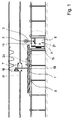
- FIG. 1 shows a joinery machine which has a support 8 for a workpiece 1, which can be moved in the longitudinal direction of the support 8 by means of a transport device 7.
- the transport device consists of a motor-driven towing device 18, which is connected to the workpiece 1 via a stamp 19.
- a processing unit 6 arranged which has a support frame 15 with a tool spindle 5 which can be displaced in the vertical and in the horizontal direction.
- the support 8 consists of a plurality of guide rollers 20 which are arranged one behind the other in the longitudinal direction of the support 8 and on which the workpiece 1 rolls during the movement through the joinery machine.
- a recess 21 is provided which receives the processing unit 6.
- This recess 21 is formed, for example, by a corresponding distance between the guide rollers 20.
- the support 8 can consist of a conveyor belt interrupted in the area of the processing units 6 or a sliding plane with a corresponding recess for the passage of the tool spindle 5.
- the support frame 15 is displaced by means of the adjusting means customary in machine and plant construction, such as hydraulic cylinders or motors, which can be controlled by a machine control.
- This machine control can be a conventional control as well as a computer-aided control (CNC control).
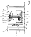
- a turntable 4 is mounted with a base 3, on which the tool spindle 5 is arranged with a tool 2. Further details of the processing unit 6 result from FIG. 2, in which the detail X in FIG. 1 is shown enlarged.
- the processing unit 6 is in a rest position shown.
- the support frame 15 is moved to the lowest position, so that the tool spindle 5 with the tools 2 ', 2''and2''' is arranged below the plane of the support 8.
- the turntable 4 is rotatably mounted on which the base 3 is fastened.
- the drive motor 12 for the spindle drive of the tool spindle 5 is arranged on the turntable 4.
- the drive force is transmitted via a belt drive, for example a toothed or V-belt 22, to the tool spindle 5 arranged in the upper region of the base 3.
- the turntable 4 itself can be driven by an actuator 9, which is also arranged in the support frame 15.
- the turntable 4 can consist, for example, of a pulley which is rotated by the servomotor 9 via a V-belt depending on the system control.
- the turntable 4 can also consist of a gear wheel which is driven by a pinion driven by the servomotor 9.
- the tool spindle 5 Due to the arrangement of the tool spindle 5 in the upper region of the base 3, which can be rotated with the rotary plate 4, it can be rotated about the axis of rotation D.
- the tool spindle 5 is supported with its central region via two roller bearings in the upper end region of the base 3 and has a radial milling cutter 2 'and a face milling cutter 2' 'on its ends projecting on both sides of the pedestal 3.
- the radial milling cutter 2 'additionally has on its side used for mounting the tool spindle an end mill 2' '' with which smaller grooves or cylindrical recesses can be produced.
- Fig. 2 it is indicated that several tools 2 are used on the tool spindle.
- the left one of the tool spindle initially carries a radial milling cutter 3 with a correspondingly large diameter and a finger milling cutter 2 '''is arranged on its left extension of the tool spindle, whereby the flexibility of the joinery system according to the invention is increased.
- the ends of the tool spindle 5 have chucks 10, 11.
- the drive motor 12 can also be arranged in the end region of the base 3.
- the power transmission to the tool spindle 5 can be simplified, but the relatively heavy motor 12 causes undesirable vibrations of the base, so that it must be reinforced accordingly.
- tool spindles 5 can also be arranged on the base 3, which are either driven by a motor via a corresponding gear, or can be driven by several motors.
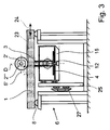
- FIG. 3 shows the processing unit 6 from FIG. 2 during the processing of a beam-shaped wooden workpiece 1.
- a radial milling cutter 2 'driven by the tool spindle 5 is working a longitudinal groove into the top of the workpiece 1.
- the support frame 15 has been moved vertically upwards and transversely to the support 8, so that the radial milling cutter 2 'has assumed the required position.
- the tool spindle 5 was rotated through 90 ° about the axis of rotation D in order to align the tool 2 ′ for milling the longitudinal groove 23.
- the radial milling cutter 2 ′ works the groove 23 into the workpiece 1.
- the transport device 7 is able to guide the workpiece 1 so precisely that the desired manufacturing accuracy is achieved.
- the feed movement of the transport device 7 is identified by the double arrow 24.
- the transport device 7 embosses a movement in both directions, forwards, on the wooden workpiece and backwards, one.
- the workpiece 1 is moved in the forward direction of the joinery machine. After this processing has been completed, further processing can then be carried out by changing the direction of the workpiece movement and by possibly rotating or transversely displacing the tool spindle 5.
- the support frame 15 is guided vertically on a guide tree 25.
- the drive means necessary for this are not shown for the sake of clarity.
- the guide tree 25 is slidably arranged for horizontal movement.
- the guide tree 25 is mounted on slide bearings 26.
- the guide tree 25 is provided, for example, on both sides of the support frame 15.
- a guide 27 is provided for movement in the horizontal direction. Such a configuration achieves a movement of the support frame in a plane which is here perpendicular to the plane of the drawing. A different configuration can be selected by a corresponding configuration of the guide 27.
- the definition of the spindle axis 5 ' also includes the axis about which the tool 2 rotates.
Landscapes
- Engineering & Computer Science (AREA)
- Mechanical Engineering (AREA)
- Life Sciences & Earth Sciences (AREA)
- Wood Science & Technology (AREA)
- Forests & Forestry (AREA)
- Milling, Drilling, And Turning Of Wood (AREA)
- Treatment Of Steel In Its Molten State (AREA)
- Compositions Of Macromolecular Compounds (AREA)
- Saccharide Compounds (AREA)
- Drilling And Boring (AREA)
- Turning (AREA)
- Pressure Welding/Diffusion-Bonding (AREA)
Priority Applications (1)
| Application Number | Priority Date | Filing Date | Title |
|---|---|---|---|
| DE29723243U DE29723243U1 (de) | 1996-06-17 | 1997-06-16 | Abbundanlage zur Bearbeitung von Strangmaterial |
Applications Claiming Priority (2)
| Application Number | Priority Date | Filing Date | Title |
|---|---|---|---|
| DE19624138A DE19624138A1 (de) | 1996-06-17 | 1996-06-17 | Abbundanlage zur Bearbeitung von Strangmaterial |
| DE19624138 | 1996-06-17 |
Publications (4)
| Publication Number | Publication Date |
|---|---|
| EP0813941A2 true EP0813941A2 (fr) | 1997-12-29 |
| EP0813941A3 EP0813941A3 (fr) | 1998-07-29 |
| EP0813941B1 EP0813941B1 (fr) | 2005-08-03 |
| EP0813941B2 EP0813941B2 (fr) | 2010-01-13 |
Family
ID=7797170
Family Applications (1)
| Application Number | Title | Priority Date | Filing Date |
|---|---|---|---|
| EP97109751A Expired - Lifetime EP0813941B2 (fr) | 1996-06-17 | 1997-06-16 | Machine-outil pour l'usinage de pièces allongées |
Country Status (3)
| Country | Link |
|---|---|
| EP (1) | EP0813941B2 (fr) |
| AT (1) | ATE301028T1 (fr) |
| DE (2) | DE19624138A1 (fr) |
Cited By (4)
| Publication number | Priority date | Publication date | Assignee | Title |
|---|---|---|---|---|
| EP0894565A3 (fr) * | 1997-08-02 | 1999-12-15 | Engelbert Güntert | Machine de taillage |
| WO2013104706A1 (fr) * | 2012-01-14 | 2013-07-18 | Hans Hundegger | Installation de traitement du bois, et procédé permettant de faire fonctionner ladite installation de traitement du bois |
| ITPD20120181A1 (it) * | 2012-06-06 | 2013-12-07 | Essetre Holding Spa | Centro di lavoro perfezionato per la lavorazione di travi, particolarmente per la lavorazione di travi in legno e simili |
| EP2894018B1 (fr) * | 2010-02-10 | 2018-03-14 | Hans Hundegger | Installation de traitement de bois |
Families Citing this family (2)
| Publication number | Priority date | Publication date | Assignee | Title |
|---|---|---|---|---|
| DE19716971C9 (de) * | 1997-04-15 | 2012-05-31 | R.M.G. Schmidler Gmbh | Abbundanlage |
| DE102014108480A1 (de) * | 2014-06-17 | 2015-12-17 | Hans Hundegger | Verfahren zur Durchführung von Abbundarbeiten an einem Holzbauteil |
Family Cites Families (7)
| Publication number | Priority date | Publication date | Assignee | Title |
|---|---|---|---|---|
| DE182321C (fr) * | ||||
| US1789398A (en) * | 1927-11-18 | 1931-01-20 | Aubertin Wilhelm Thure | Machine for working wood |
| US2672170A (en) * | 1950-05-19 | 1954-03-16 | Arthur C Johnson | Electrically driven speed reducing power unit |
| US4589174A (en) * | 1984-03-27 | 1986-05-20 | Brigham Young University | Polar coordinate apparatus |
| DE3741171A1 (de) * | 1987-12-04 | 1989-06-15 | Hans Kuehl | Zimmerei-abbundanlage |
| IT1238935B (it) * | 1990-05-23 | 1993-09-07 | Bacci Paolino Di Giuseppe Bacc | Macchina utensile per la realizzazione di giunti su elementi costruttivi di mobili e simili |
| DE4301217A1 (de) * | 1993-01-19 | 1994-07-21 | Baljer & Zembrod | CNC-gesteuerte Holzbearbeitungsanlage, insbesondere für lange Werkstücke wie Balken |
-
1996
- 1996-06-17 DE DE19624138A patent/DE19624138A1/de not_active Withdrawn
-
1997
- 1997-06-16 AT AT97109751T patent/ATE301028T1/de active
- 1997-06-16 DE DE59712380T patent/DE59712380D1/de not_active Expired - Lifetime
- 1997-06-16 EP EP97109751A patent/EP0813941B2/fr not_active Expired - Lifetime
Cited By (6)
| Publication number | Priority date | Publication date | Assignee | Title |
|---|---|---|---|---|
| EP0894565A3 (fr) * | 1997-08-02 | 1999-12-15 | Engelbert Güntert | Machine de taillage |
| EP2894018B1 (fr) * | 2010-02-10 | 2018-03-14 | Hans Hundegger | Installation de traitement de bois |
| WO2013104706A1 (fr) * | 2012-01-14 | 2013-07-18 | Hans Hundegger | Installation de traitement du bois, et procédé permettant de faire fonctionner ladite installation de traitement du bois |
| US9815164B2 (en) | 2012-01-14 | 2017-11-14 | Hans Hundegger | Wood-working machine and method for the operation thereof |
| ITPD20120181A1 (it) * | 2012-06-06 | 2013-12-07 | Essetre Holding Spa | Centro di lavoro perfezionato per la lavorazione di travi, particolarmente per la lavorazione di travi in legno e simili |
| EP2671697A1 (fr) * | 2012-06-06 | 2013-12-11 | Essetre Holding SpA | Centre d'usinage pour l'usinage de poutres, en particulier des poutres en bois ou similaire |
Also Published As
| Publication number | Publication date |
|---|---|
| DE59712380D1 (de) | 2005-09-08 |
| EP0813941A3 (fr) | 1998-07-29 |
| EP0813941B1 (fr) | 2005-08-03 |
| EP0813941B2 (fr) | 2010-01-13 |
| DE19624138A1 (de) | 1997-12-18 |
| ATE301028T1 (de) | 2005-08-15 |
Similar Documents
| Publication | Publication Date | Title |
|---|---|---|
| DE4113629C2 (de) | Reihenbohr- und Fräsmaschine | |
| DE19915672C2 (de) | Vorrichtung zum Bearbeiten von Kanten eines plattenförmigen Werkstückes mit mehreren Spanwerkzeugen | |
| DE102016114252B4 (de) | Innenfräs-Maschine | |
| EP0332149B1 (fr) | Dispositif pour le fraisage de profils sur des planches en bois | |
| EP1600254B1 (fr) | Unité d'avance pour machine à usiner des pièces et méthode pour usiner ces pièces | |
| EP0106907A1 (fr) | Scie à lames circulaires dont les lames sont réglables | |
| DE4031911A1 (de) | Vorrichtung zum bearbeiten von stangen | |
| EP1346788A2 (fr) | Centre d'usinage | |
| EP0813941B2 (fr) | Machine-outil pour l'usinage de pièces allongées | |
| EP3311967B1 (fr) | Dispositif à travailler le bois | |
| EP0787560B1 (fr) | Dispositif d'usinage des barres, des profilés et similaire | |
| DE4419324C2 (de) | Vorrichtung zum Bearbeiten von Holz | |
| WO1985005062A1 (fr) | Installation de sciage et de coupe pour troncs d'arbre | |
| DE69020870T2 (de) | Mehrspindel-Drehautomat. | |
| EP2185331B1 (fr) | Installation de traitement de pieces en bois, matiere plastique et analogues, et procede de traitement de telles pieces | |
| EP0292864B1 (fr) | Machine pour travailler le bois | |
| DE10147649C2 (de) | Fräsaggregat | |
| DE292957C (fr) | ||
| DE19831284C2 (de) | Abbundanlage zur Bearbeitung von Strangmaterial | |
| DE4401044B4 (de) | Hobelmaschine | |
| DE4326890A1 (de) | Vorrichtung zum Schleifen der Kanten von platten- oder tafelförmigen Werkstücken | |
| EP0059979A2 (fr) | Machine pour le fraisage de rainures dans la paroi d'alésages de pièces | |
| DE3717411C2 (fr) | ||
| DE29723243U1 (de) | Abbundanlage zur Bearbeitung von Strangmaterial | |
| DE19721521C2 (de) | Numerisch gesteuerte Zapfenschneidmaschine |
Legal Events
| Date | Code | Title | Description |
|---|---|---|---|
| PUAI | Public reference made under article 153(3) epc to a published international application that has entered the european phase |
Free format text: ORIGINAL CODE: 0009012 |
|
| AK | Designated contracting states |
Kind code of ref document: A2 Designated state(s): AT CH DE FI FR IT LI SE |
|
| PUAL | Search report despatched |
Free format text: ORIGINAL CODE: 0009013 |
|
| AK | Designated contracting states |
Kind code of ref document: A3 Designated state(s): AT BE CH DE DK ES FI FR GB GR IE IT LI LU MC NL PT SE |
|
| 17P | Request for examination filed |
Effective date: 19981010 |
|
| AKX | Designation fees paid |
Free format text: AT CH DE FI FR IT LI SE |
|
| RBV | Designated contracting states (corrected) |
Designated state(s): AT CH DE FI FR IT LI SE |
|
| 17Q | First examination report despatched |
Effective date: 20020802 |
|
| GRAP | Despatch of communication of intention to grant a patent |
Free format text: ORIGINAL CODE: EPIDOSNIGR1 |
|
| GRAS | Grant fee paid |
Free format text: ORIGINAL CODE: EPIDOSNIGR3 |
|
| GRAA | (expected) grant |
Free format text: ORIGINAL CODE: 0009210 |
|
| AK | Designated contracting states |
Kind code of ref document: B1 Designated state(s): AT CH DE FI FR IT LI SE |
|
| REG | Reference to a national code |
Ref country code: CH Ref legal event code: EP |
|
| REF | Corresponds to: |
Ref document number: 59712380 Country of ref document: DE Date of ref document: 20050908 Kind code of ref document: P |
|
| REG | Reference to a national code |
Ref country code: CH Ref legal event code: NV Representative=s name: PA ALDO ROEMPLER |
|
| REG | Reference to a national code |
Ref country code: SE Ref legal event code: TRGR |
|
| ET | Fr: translation filed | ||
| PLBI | Opposition filed |
Free format text: ORIGINAL CODE: 0009260 |
|
| PLAX | Notice of opposition and request to file observation + time limit sent |
Free format text: ORIGINAL CODE: EPIDOSNOBS2 |
|
| 26 | Opposition filed |
Opponent name: R.M.G. SCHMIDLER GMBH Effective date: 20060428 |
|
| PLBB | Reply of patent proprietor to notice(s) of opposition received |
Free format text: ORIGINAL CODE: EPIDOSNOBS3 |
|
| REG | Reference to a national code |
Ref country code: CH Ref legal event code: PCAR Free format text: ALDO ROEMPLER PATENTANWALT;BRENDENWEG 11 POSTFACH 154;9424 RHEINECK (CH) |
|
| APBM | Appeal reference recorded |
Free format text: ORIGINAL CODE: EPIDOSNREFNO |
|
| APBP | Date of receipt of notice of appeal recorded |
Free format text: ORIGINAL CODE: EPIDOSNNOA2O |
|
| APAH | Appeal reference modified |
Free format text: ORIGINAL CODE: EPIDOSCREFNO |
|
| APBQ | Date of receipt of statement of grounds of appeal recorded |
Free format text: ORIGINAL CODE: EPIDOSNNOA3O |
|
| APBU | Appeal procedure closed |
Free format text: ORIGINAL CODE: EPIDOSNNOA9O |
|
| PUAH | Patent maintained in amended form |
Free format text: ORIGINAL CODE: 0009272 |
|
| STAA | Information on the status of an ep patent application or granted ep patent |
Free format text: STATUS: PATENT MAINTAINED AS AMENDED |
|
| 27A | Patent maintained in amended form |
Effective date: 20100113 |
|
| AK | Designated contracting states |
Kind code of ref document: B2 Designated state(s): AT CH DE FI FR IT LI SE |
|
| REG | Reference to a national code |
Ref country code: CH Ref legal event code: AEN Free format text: AUFRECHTERHALTUNG DES PATENTES IN GEAENDERTER FORM |
|
| REG | Reference to a national code |
Ref country code: SE Ref legal event code: RPEO |
|
| REG | Reference to a national code |
Ref country code: DE Ref legal event code: R008 Ref document number: 59712380 Country of ref document: DE |
|
| REG | Reference to a national code |
Ref country code: DE Ref legal event code: R097 Ref document number: 59712380 Country of ref document: DE |
|
| REG | Reference to a national code |
Ref country code: DE Ref legal event code: R040 Ref document number: 59712380 Country of ref document: DE Effective date: 20140213 |
|
| REG | Reference to a national code |
Ref country code: FR Ref legal event code: PLFP Year of fee payment: 20 |
|
| PGFP | Annual fee paid to national office [announced via postgrant information from national office to epo] |
Ref country code: FI Payment date: 20160606 Year of fee payment: 20 |
|
| PGFP | Annual fee paid to national office [announced via postgrant information from national office to epo] |
Ref country code: SE Payment date: 20160622 Year of fee payment: 20 Ref country code: FR Payment date: 20160614 Year of fee payment: 20 Ref country code: AT Payment date: 20160627 Year of fee payment: 20 |
|
| PGFP | Annual fee paid to national office [announced via postgrant information from national office to epo] |
Ref country code: DE Payment date: 20160804 Year of fee payment: 20 Ref country code: CH Payment date: 20160927 Year of fee payment: 20 Ref country code: IT Payment date: 20160622 Year of fee payment: 20 |
|
| REG | Reference to a national code |
Ref country code: DE Ref legal event code: R071 Ref document number: 59712380 Country of ref document: DE |
|
| REG | Reference to a national code |
Ref country code: CH Ref legal event code: PL |
|
| REG | Reference to a national code |
Ref country code: SE Ref legal event code: EUG |
|
| REG | Reference to a national code |
Ref country code: AT Ref legal event code: MK07 Ref document number: 301028 Country of ref document: AT Kind code of ref document: T Effective date: 20170616 |