EP0814002A2 - Procédé pour connecter une unité de commande avec un dispositif de détection de l'état d'un système de sécurité passive dans un véhicule à moteur - Google Patents
Procédé pour connecter une unité de commande avec un dispositif de détection de l'état d'un système de sécurité passive dans un véhicule à moteur Download PDFInfo
- Publication number
- EP0814002A2 EP0814002A2 EP97109368A EP97109368A EP0814002A2 EP 0814002 A2 EP0814002 A2 EP 0814002A2 EP 97109368 A EP97109368 A EP 97109368A EP 97109368 A EP97109368 A EP 97109368A EP 0814002 A2 EP0814002 A2 EP 0814002A2
- Authority
- EP
- European Patent Office
- Prior art keywords
- detection device
- control unit
- state detection
- voltage
- circuit
- Prior art date
- Legal status (The legal status is an assumption and is not a legal conclusion. Google has not performed a legal analysis and makes no representation as to the accuracy of the status listed.)
- Granted
Links
Images

Classifications
-
- B—PERFORMING OPERATIONS; TRANSPORTING
- B60—VEHICLES IN GENERAL
- B60R—VEHICLES, VEHICLE FITTINGS, OR VEHICLE PARTS, NOT OTHERWISE PROVIDED FOR
- B60R21/00—Arrangements or fittings on vehicles for protecting or preventing injuries to occupants or pedestrians in case of accidents or other traffic risks
- B60R21/01—Electrical circuits for triggering passive safety arrangements, e.g. airbags, safety belt tighteners, in case of vehicle accidents or impending vehicle accidents
- B60R21/015—Electrical circuits for triggering passive safety arrangements, e.g. airbags, safety belt tighteners, in case of vehicle accidents or impending vehicle accidents including means for detecting the presence or position of passengers, passenger seats or child seats, and the related safety parameters therefor, e.g. speed or timing of airbag inflation in relation to occupant position or seat belt use
- B60R21/01512—Passenger detection systems
- B60R21/01544—Passenger detection systems detecting seat belt parameters, e.g. length, tension or height-adjustment
- B60R21/01546—Passenger detection systems detecting seat belt parameters, e.g. length, tension or height-adjustment using belt buckle sensors
-
- B—PERFORMING OPERATIONS; TRANSPORTING
- B60—VEHICLES IN GENERAL
- B60R—VEHICLES, VEHICLE FITTINGS, OR VEHICLE PARTS, NOT OTHERWISE PROVIDED FOR
- B60R21/00—Arrangements or fittings on vehicles for protecting or preventing injuries to occupants or pedestrians in case of accidents or other traffic risks
- B60R21/01—Electrical circuits for triggering passive safety arrangements, e.g. airbags, safety belt tighteners, in case of vehicle accidents or impending vehicle accidents
- B60R21/015—Electrical circuits for triggering passive safety arrangements, e.g. airbags, safety belt tighteners, in case of vehicle accidents or impending vehicle accidents including means for detecting the presence or position of passengers, passenger seats or child seats, and the related safety parameters therefor, e.g. speed or timing of airbag inflation in relation to occupant position or seat belt use
- B60R21/01512—Passenger detection systems
- B60R21/01516—Passenger detection systems using force or pressure sensing means
- B60R21/01526—Passenger detection systems using force or pressure sensing means using piezoelectric elements
Definitions
- the invention relates to a method for connecting a state detection device of a passive safety system for motor vehicles to a control unit.
- condition detection devices of additional devices of such security systems such as occupant seat occupancy detection, seat belt buckle condition detection, function reliably and provide reliable condition information, so that adequate protection is provided for the motor vehicle occupants in an emergency.
- the object of the invention is to provide a method with which various state detection devices that work with different physical principles of operation can be connected to the control unit of the security system in a simple and inexpensive manner, so that the signal generated by the respectively connected state detection device Control unit of the security system can be fed in an evaluable form.
- the signal is processed into an analog or digital signal depending on the physical mode of operation of the state detection device. These signals are then preferably fed to the analog or digital input of the control unit. In this way, the corresponding input of the control unit can advantageously be activated in software, preferably with a software-controlled switch.
- state detection devices of the first and second type are provided such that the state detection device of the first type works with a mechanical principle of operation for state detection, in particular by means of a micromechanical switch, whereas the state detection device second type works with a non-mechanical principle of action, in particular with Hall sensors, infrared sensors, piezoelectric, magnetostrictive, electrodynamic, capacitive or piezoresistive sensors.
- both the voltage source is switched on by the control unit and the analog signal is fed to the analog input of the control unit.
- both the voltage-stabilized current source is switched on by the control unit and the digital signal is fed to the digital input of the control unit.
- an interface circuit which is connected via the single-wire connection to the state detection device and which has a voltage source which can be switched by the control unit and which, when switched on, supplies a connected state detection device of the first type with an operating voltage and which also supplies an operating voltage also has a voltage-stabilized current source which can be switched by the control unit and which, in the switched-on state, may supply an operating current to a connected state-recognition device of the second type.
- circuit means are provided which are connected to the analog input of the control unit in the case of a connected state detection device of the first type and at the same time a comparison circuit is implemented in the interface circuit for generating a digital signal, which is implemented in the case of a connected state detection device of the second type is connected to the digital input of the control unit, the comparison circuit comparing a voltage potential generated on the single-wire connection with a reference voltage.
- the proposed interface circuit can thus advantageously process both analog and digital signals as an input.
- a resistance network can be provided as circuit means and a resistance network and a comparator can also be provided as comparison circuit, the same resistance network being usable in each case.
- the single-wire connection used in the interface circuit represents a connector pin of a connector.
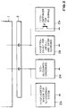
- An interface circuit 1 contains a voltage source 3, a voltage-stabilized current source 4, two comparators K 1 and K 2 and four resistors R s11 , R s12 , R s21 and R s22 .
- This interface circuit 1 is connected via plug pins 2a and 2b of a plug connection 2 to a status detection device Z 11 or Z 21 and Z 22 or Z 12 , respectively.
- condition detection devices Z 11 to Z 22 represent belt buckle condition detections - Z 11 and Z 21 or Z 12 and Z 22 for the driver or front passenger side - which are based on various physical principles of operation.
- the two state detection devices Z 21 and Z 22 contain a micromechanical belt buckle contact switch G 1 and G 2 , which, when the belt buckle is engaged, bridges a further resistor R 12 and R 22 in series with a resistor R 11 and R 21 , respectively.
- the required operating voltage is supplied from the 5 V voltage source 3 is connected via the resistor R s11 with the connector pin 2a and via the resistor R s21 with the connector pin 2b.
- the switchability of the voltage source 3 is realized by means of a semiconductor switch which is controlled via an input / output unit I / O of a control unit, in particular a microprocessor ⁇ P.
- This microprocessor ⁇ P represents the control unit of a security system, for example an airbar system.
- the voltage signal generated at connector pin 2a or 2b is fed via resistor R s12 or R s22 to an analog input of an A / D converter of the microprocessor ⁇ P for evaluation, where this voltage signal is used before evaluation is digitized. Since the status detection device connected to the plug pin 2a detects the belt buckle state on the driver's side and that connected to the plug pin 2b detects the belt buckle state on the front passenger side, the microprocessor ⁇ P has the information whether the driver or the front passenger has fastened the seat belt to decide whether the front passenger airbag and other safety devices should be deployed.
- These state detection devices Z 11 and Z 12 contain a Hall sensor H 1 or H 2 , which turns on a transistor T 1 or T 2 when the belt buckle is engaged.
- the z. B. instead of the voltage source 3, the voltage-stabilized current source 4 switched on by the microprocessor .mu.P, the z. B. is powered by a 24 V voltage source and can deliver a current of 50 mA.
- Such an operating current feeds the Hall sensor H 1 or H 2 , the z. B. takes a maximum of 10 mA, and a controlled by the transistor T 1 or T 2 circuit, the z. B. consists of a Zener diode D 1 and D 2 and a resistor R H1 and R H2 .
- a voltage potential is generated at the connector pin 2a or 2b, which is led to one input of a comparator K 1 or K 2 via the resistor R s12 or R s22 .
- a reference voltage preferably 12 V, is applied to the other input of this comparator K 1 or K 2 .
- a digital signal thus appears at the output of this comparator K 1 or K 2 , which indicates the state of the buckle and is fed to the digital input of the microprocessor ⁇ P for evaluation.
- the digital input leads to the input / output unit I / O of the microprocessor ⁇ P.
- this interface circuit 1 it is thus possible to connect state detection devices to the microprocessor ⁇ P via the single-wire connection 2a or 2b, each of which works with different physical principles of operation.
- the control unit ⁇ P is set to this by means of a software-controlled switch, so that either the voltage source 3 or the voltage-stabilized current source 4 is switched and for this purpose the signal present at the corresponding analog or digital input is evaluated.
- the interface circuit 1 according to FIG. 1 also has the advantage that it can evaluate both analog and digital signals as an input circuit and can therefore also be designated as a multifunctional interface.
- the interface circuit 1 can also transmit status information of other additional devices of a security system.
- status data from a seat occupancy detection Z 4 in particular a child occupancy detection
- data from an outsourced system such as. B. a side impact sensor Z 3
- data for a recording unit of an accident and data recorder Z 5 and data of a photo receiver Z 6 of infrared signals are transmitted.
- the dimensioning of the interface circuit 1 must be adapted to the respective status detection devices.
- the interface circuit 1 shown in FIG. 1 only has a single-wire connection to the state detection device.
- a multi-wire connection is also conceivable in which, for example, the ground line serves as a return line.
Landscapes
- Engineering & Computer Science (AREA)
- Mechanical Engineering (AREA)
- Air Bags (AREA)
- Automotive Seat Belt Assembly (AREA)
Applications Claiming Priority (2)
| Application Number | Priority Date | Filing Date | Title |
|---|---|---|---|
| DE19624199 | 1996-06-18 | ||
| DE19624199A DE19624199C1 (de) | 1996-06-18 | 1996-06-18 | Verfahren zum Verbinden einer Zustandserkennungsvorrichtung eines passiven Sicherheitssystems für Kraftfahrzeuge mit einer Steuereinheit |
Publications (3)
| Publication Number | Publication Date |
|---|---|
| EP0814002A2 true EP0814002A2 (fr) | 1997-12-29 |
| EP0814002A3 EP0814002A3 (fr) | 1999-12-01 |
| EP0814002B1 EP0814002B1 (fr) | 2002-01-30 |
Family
ID=7797213
Family Applications (1)
| Application Number | Title | Priority Date | Filing Date |
|---|---|---|---|
| EP97109368A Expired - Lifetime EP0814002B1 (fr) | 1996-06-18 | 1997-06-10 | Procédé pour connecter une unité de commande avec un dispositif de détection de l'état d'un système de sécurité passive dans un véhicule à moteur |
Country Status (5)
| Country | Link |
|---|---|
| US (1) | US5982048A (fr) |
| EP (1) | EP0814002B1 (fr) |
| JP (1) | JPH1071927A (fr) |
| DE (2) | DE19624199C1 (fr) |
| ES (1) | ES2170300T3 (fr) |
Cited By (1)
| Publication number | Priority date | Publication date | Assignee | Title |
|---|---|---|---|---|
| FR3085334A1 (fr) * | 2018-08-29 | 2020-03-06 | Autoliv Development Ab | Dispositif de detection de vehicule et son procede de fabrication |
Families Citing this family (24)
| Publication number | Priority date | Publication date | Assignee | Title |
|---|---|---|---|---|
| US5917405A (en) | 1993-06-08 | 1999-06-29 | Joao; Raymond Anthony | Control apparatus and methods for vehicles |
| US7397363B2 (en) | 1993-06-08 | 2008-07-08 | Raymond Anthony Joao | Control and/or monitoring apparatus and method |
| US6542077B2 (en) | 1993-06-08 | 2003-04-01 | Raymond Anthony Joao | Monitoring apparatus for a vehicle and/or a premises |
| US10011247B2 (en) | 1996-03-27 | 2018-07-03 | Gtj Ventures, Llc | Control, monitoring and/or security apparatus and method |
| US7277010B2 (en) | 1996-03-27 | 2007-10-02 | Raymond Anthony Joao | Monitoring apparatus and method |
| US6587046B2 (en) | 1996-03-27 | 2003-07-01 | Raymond Anthony Joao | Monitoring apparatus and method |
| US7253731B2 (en) | 2001-01-23 | 2007-08-07 | Raymond Anthony Joao | Apparatus and method for providing shipment information |
| US10152876B2 (en) | 1996-03-27 | 2018-12-11 | Gtj Ventures, Llc | Control, monitoring, and/or security apparatus and method |
| US9075136B1 (en) | 1998-03-04 | 2015-07-07 | Gtj Ventures, Llc | Vehicle operator and/or occupant information apparatus and method |
| US6457071B1 (en) * | 1999-08-05 | 2002-09-24 | Hewlett-Packard Company | System and method for determining connection accuracy at an interface |
| KR20010018903A (ko) * | 1999-08-23 | 2001-03-15 | 이현복 | 자동차용 버클의 로킹 상태 검출회로 |
| US6250672B1 (en) | 2000-08-18 | 2001-06-26 | Ford Global Technologies, Inc. | Vehicle airbag restraint system with deactivation indicator |
| FR2817520B1 (fr) * | 2000-12-06 | 2003-04-18 | Peugeot Citroen Automobiles Sa | Dispositif permettant d'empecher le declenchement d'un actionneur a cartouche pyrotechnique de pretensionnement d'une ceinture de securite de vehicule automobile |
| US10562492B2 (en) | 2002-05-01 | 2020-02-18 | Gtj Ventures, Llc | Control, monitoring and/or security apparatus and method |
| DE10234854A1 (de) * | 2002-07-31 | 2004-02-12 | Robert Bosch Gmbh | Schalter zum Abschalten wenigstens eines Airbags |
| DE10322009A1 (de) * | 2003-05-16 | 2004-12-02 | Daimlerchrysler Ag | Auslösesteuergerät für einen Airbag |
| DE10335866A1 (de) * | 2003-08-06 | 2005-03-03 | Volkswagen Ag | Kraftfahrzeugumrichter |
| DE102004005298B4 (de) | 2004-01-29 | 2018-10-11 | Volkswagen Ag | Vorrichtung zur Gurtanschnallwarnung |
| JP4816412B2 (ja) * | 2006-11-07 | 2011-11-16 | 株式会社デンソー | スイッチ信号入力用インターフェイス回路 |
| JP5689677B2 (ja) * | 2010-12-27 | 2015-03-25 | 矢崎総業株式会社 | スイッチ回路 |
| US8731801B2 (en) | 2011-05-12 | 2014-05-20 | Delphi Technologies, Inc. | Fuel injector heater element control via single data line |
| US10546441B2 (en) | 2013-06-04 | 2020-01-28 | Raymond Anthony Joao | Control, monitoring, and/or security, apparatus and method for premises, vehicles, and/or articles |
| DE102016206589A1 (de) | 2016-04-19 | 2017-10-19 | Volkswagen Aktiengesellschaft | Überzug für ein Band |
| US10964133B2 (en) * | 2018-05-29 | 2021-03-30 | Zf Active Safety And Electronics Us Llc | Vehicle safety system with smart detection sensors |
Family Cites Families (10)
| Publication number | Priority date | Publication date | Assignee | Title |
|---|---|---|---|---|
| US4099157A (en) * | 1976-12-22 | 1978-07-04 | The Goodyear Tire & Rubber Company | Single wire power/signal system for vehicle auxiliary devices |
| KR900001050Y1 (ko) * | 1987-05-29 | 1990-02-15 | 강충석 | 시동스위치를 형성한 자동차안전 밸트의 버클 |
| JPH0226961U (fr) * | 1988-04-25 | 1990-02-21 | ||
| DE3904668A1 (de) * | 1989-02-16 | 1990-08-30 | Daimler Benz Ag | Insassen-rueckhaltesystem |
| US5411289A (en) * | 1993-10-29 | 1995-05-02 | Morton International, Inc. | Air bag system for a motor vehicle |
| DE9317678U1 (de) * | 1993-11-19 | 1995-03-16 | Autoliv Development AB, Vårgårda | Fahrzeugsicherheitssystem |
| US5626359A (en) * | 1993-12-02 | 1997-05-06 | Trw Vehicle Safety Systems, Inc. | Method and apparatus for controlling an actuatable restraining device in response to discrete control zones |
| DE4404816B4 (de) * | 1994-02-16 | 2005-08-25 | Siemens Restraint Systems Gmbh | Vorrichtung zur Übertragung von Energie und Daten zwischen der Fahrzeug- und der Lenkradseite von Kraftfahrzeugen |
| DE4420114A1 (de) * | 1994-06-09 | 1995-12-14 | Telefunken Microelectron | Auslöseeinrichtung für Personenschutzvorrichtungen in Fahrzeugen |
| US5531472A (en) * | 1995-05-01 | 1996-07-02 | Trw Vehicle Safety Systems, Inc. | Apparatus and method for controlling an occupant restraint system |
-
1996
- 1996-06-18 DE DE19624199A patent/DE19624199C1/de not_active Expired - Fee Related
-
1997
- 1997-06-09 JP JP9185651A patent/JPH1071927A/ja active Pending
- 1997-06-10 EP EP97109368A patent/EP0814002B1/fr not_active Expired - Lifetime
- 1997-06-10 DE DE59706214T patent/DE59706214D1/de not_active Expired - Lifetime
- 1997-06-10 ES ES97109368T patent/ES2170300T3/es not_active Expired - Lifetime
- 1997-06-18 US US08/877,814 patent/US5982048A/en not_active Expired - Lifetime
Cited By (1)
| Publication number | Priority date | Publication date | Assignee | Title |
|---|---|---|---|---|
| FR3085334A1 (fr) * | 2018-08-29 | 2020-03-06 | Autoliv Development Ab | Dispositif de detection de vehicule et son procede de fabrication |
Also Published As
| Publication number | Publication date |
|---|---|
| ES2170300T3 (es) | 2002-08-01 |
| EP0814002A3 (fr) | 1999-12-01 |
| JPH1071927A (ja) | 1998-03-17 |
| DE19624199C1 (de) | 1997-11-20 |
| US5982048A (en) | 1999-11-09 |
| EP0814002B1 (fr) | 2002-01-30 |
| DE59706214D1 (de) | 2002-03-14 |
Similar Documents
| Publication | Publication Date | Title |
|---|---|---|
| EP0814002B1 (fr) | Procédé pour connecter une unité de commande avec un dispositif de détection de l'état d'un système de sécurité passive dans un véhicule à moteur | |
| EP0883526B1 (fr) | Procede de declenchement d'un dispositif de retenue de securite dans un vehicule | |
| DE19609290C2 (de) | Airbagsystem | |
| DE4425845A1 (de) | Datenübertragungsverfahren in einem für den Einsatz in Kraftfahrzeugen geeigneten Datenverarbeitungssystem | |
| EP1592583B1 (fr) | Dispositif de transmission sans fil d'un signal de declenchement | |
| DE19648268A1 (de) | Fahrzeugsitz mit einer Steuervorrichtung | |
| DE4128608C2 (de) | Insassenschutzsystem für ein Kraftfahrzeug | |
| DE102007008091B4 (de) | Fahrzeuginsassen-Schutzvorrichtung | |
| DE19541998B4 (de) | Airbagsystem für ein Kraftfahrzeug | |
| DE19646387A1 (de) | Steuerverfahren für ein System, insbesondere für ein Sicherheitssystem in Kraftfahrzeugen | |
| EP1817208B1 (fr) | Circuit integre | |
| DE112005000075B4 (de) | Vorrichtung zur Aktivierung einer Insassen-Schutzeinrichtung eines Fahrzeugs | |
| DE102006028667B4 (de) | Passagier-Schutzsystem zum Schützen von Passagieren in einem Fahrzeug vor einer Kollision | |
| DE102006036861B4 (de) | Passagier-Schutzsystem | |
| DE19829756C1 (de) | Auslösegerät für ein Insassenschutzsystem | |
| DE102004005298B4 (de) | Vorrichtung zur Gurtanschnallwarnung | |
| DE19546359A1 (de) | System mit zwei voneinander räumlich getrennten elektrischen Schaltungsanordnungen, und mit einer Leitung zwischen den Schaltungsanordnungen | |
| DE19536573C1 (de) | System zum Auslösen eines Rückhaltemittels in einem Fahrzeug | |
| DE102005001686B4 (de) | Schaltungsanordung zum Detektieren eines Kurzschlusses | |
| DE102004008616A1 (de) | Verfahren und Vorrichtung zur Erfassung und Verarbeitung des Luftdruckes in einem Fahrzeug | |
| DE102008040317B4 (de) | Steuergerät und Verfahren zur Ansteuerung von Personenschutzmitteln für ein Fahrzeug | |
| DE102007011277B4 (de) | Verfahren und Vorrichtung zur Sitzüberwachung | |
| EP2225126A1 (fr) | Appareil de commande et procédé pour commander des moyens de protection des personnes | |
| DE102005011391A1 (de) | Passives Sicherheitssystem | |
| DE10349888B4 (de) | Codierte Zündeinheit für ein Airbag-Modul sowie damit ausgerüstetes Airbag-Modul für ein Kraftfahrzeug-Airbag-System |
Legal Events
| Date | Code | Title | Description |
|---|---|---|---|
| PUAI | Public reference made under article 153(3) epc to a published international application that has entered the european phase |
Free format text: ORIGINAL CODE: 0009012 |
|
| AK | Designated contracting states |
Kind code of ref document: A2 Designated state(s): DE ES FR GB IT SE |
|
| PUAL | Search report despatched |
Free format text: ORIGINAL CODE: 0009013 |
|
| AK | Designated contracting states |
Kind code of ref document: A3 Designated state(s): AT BE CH DE DK ES FI FR GB GR IE IT LI LU MC NL PT SE |
|
| RAP1 | Party data changed (applicant data changed or rights of an application transferred) |
Owner name: BAYERISCHE MOTOREN WERKE AKTIENGESELLSCHAFT Owner name: TEMIC TELEFUNKEN MICROELECTRONIC GMBH |
|
| 17P | Request for examination filed |
Effective date: 20000404 |
|
| AKX | Designation fees paid |
Free format text: DE ES FR GB IT SE |
|
| GRAG | Despatch of communication of intention to grant |
Free format text: ORIGINAL CODE: EPIDOS AGRA |
|
| GRAG | Despatch of communication of intention to grant |
Free format text: ORIGINAL CODE: EPIDOS AGRA |
|
| GRAH | Despatch of communication of intention to grant a patent |
Free format text: ORIGINAL CODE: EPIDOS IGRA |
|
| GRAH | Despatch of communication of intention to grant a patent |
Free format text: ORIGINAL CODE: EPIDOS IGRA |
|
| 17Q | First examination report despatched |
Effective date: 20010622 |
|
| ITF | It: translation for a ep patent filed | ||
| RAP1 | Party data changed (applicant data changed or rights of an application transferred) |
Owner name: BAYERISCHE MOTOREN WERKE AKTIENGESELLSCHAFT Owner name: CONTI TEMIC MICROELECTRONIC GMBH |
|
| GRAA | (expected) grant |
Free format text: ORIGINAL CODE: 0009210 |
|
| REG | Reference to a national code |
Ref country code: GB Ref legal event code: IF02 |
|
| AK | Designated contracting states |
Kind code of ref document: B1 Designated state(s): DE ES FR GB IT SE |
|
| REF | Corresponds to: |
Ref document number: 59706214 Country of ref document: DE Date of ref document: 20020314 |
|
| GBT | Gb: translation of ep patent filed (gb section 77(6)(a)/1977) |
Effective date: 20020407 |
|
| ET | Fr: translation filed | ||
| REG | Reference to a national code |
Ref country code: ES Ref legal event code: FG2A Ref document number: 2170300 Country of ref document: ES Kind code of ref document: T3 |
|
| PLBE | No opposition filed within time limit |
Free format text: ORIGINAL CODE: 0009261 |
|
| STAA | Information on the status of an ep patent application or granted ep patent |
Free format text: STATUS: NO OPPOSITION FILED WITHIN TIME LIMIT |
|
| 26N | No opposition filed | ||
| PGFP | Annual fee paid to national office [announced via postgrant information from national office to epo] |
Ref country code: DE Payment date: 20120622 Year of fee payment: 16 |
|
| PGFP | Annual fee paid to national office [announced via postgrant information from national office to epo] |
Ref country code: GB Payment date: 20120622 Year of fee payment: 16 Ref country code: FR Payment date: 20120705 Year of fee payment: 16 Ref country code: SE Payment date: 20120621 Year of fee payment: 16 |
|
| PGFP | Annual fee paid to national office [announced via postgrant information from national office to epo] |
Ref country code: ES Payment date: 20120627 Year of fee payment: 16 Ref country code: IT Payment date: 20120628 Year of fee payment: 16 |
|
| REG | Reference to a national code |
Ref country code: DE Ref legal event code: R119 Ref document number: 59706214 Country of ref document: DE |
|
| PG25 | Lapsed in a contracting state [announced via postgrant information from national office to epo] |
Ref country code: SE Free format text: LAPSE BECAUSE OF NON-PAYMENT OF DUE FEES Effective date: 20130611 |
|
| REG | Reference to a national code |
Ref country code: SE Ref legal event code: EUG |
|
| GBPC | Gb: european patent ceased through non-payment of renewal fee |
Effective date: 20130610 |
|
| REG | Reference to a national code |
Ref country code: FR Ref legal event code: ST Effective date: 20140228 |
|
| PG25 | Lapsed in a contracting state [announced via postgrant information from national office to epo] |
Ref country code: GB Free format text: LAPSE BECAUSE OF NON-PAYMENT OF DUE FEES Effective date: 20130610 Ref country code: DE Free format text: LAPSE BECAUSE OF NON-PAYMENT OF DUE FEES Effective date: 20140101 |
|
| PG25 | Lapsed in a contracting state [announced via postgrant information from national office to epo] |
Ref country code: FR Free format text: LAPSE BECAUSE OF NON-PAYMENT OF DUE FEES Effective date: 20130701 Ref country code: IT Free format text: LAPSE BECAUSE OF NON-PAYMENT OF DUE FEES Effective date: 20130610 |
|
| REG | Reference to a national code |
Ref country code: DE Ref legal event code: R079 Ref document number: 59706214 Country of ref document: DE Free format text: PREVIOUS MAIN CLASS: B60R0021320000 Ipc: B60R0021010000 |
|
| REG | Reference to a national code |
Ref country code: ES Ref legal event code: FD2A Effective date: 20140707 |
|
| REG | Reference to a national code |
Ref country code: DE Ref legal event code: R119 Ref document number: 59706214 Country of ref document: DE Effective date: 20140101 Ref country code: DE Ref legal event code: R079 Ref document number: 59706214 Country of ref document: DE Free format text: PREVIOUS MAIN CLASS: B60R0021320000 Ipc: B60R0021010000 Effective date: 20140530 |
|
| PG25 | Lapsed in a contracting state [announced via postgrant information from national office to epo] |
Ref country code: ES Free format text: LAPSE BECAUSE OF NON-PAYMENT OF DUE FEES Effective date: 20130611 |