EP0814207A2 - Système de commande de verrouillage auxiliaire pour machine motrice - Google Patents
Système de commande de verrouillage auxiliaire pour machine motrice Download PDFInfo
- Publication number
- EP0814207A2 EP0814207A2 EP97109475A EP97109475A EP0814207A2 EP 0814207 A2 EP0814207 A2 EP 0814207A2 EP 97109475 A EP97109475 A EP 97109475A EP 97109475 A EP97109475 A EP 97109475A EP 0814207 A2 EP0814207 A2 EP 0814207A2
- Authority
- EP
- European Patent Office
- Prior art keywords
- auxiliary
- hydraulic
- control circuit
- valve
- coupled
- Prior art date
- Legal status (The legal status is an assumption and is not a legal conclusion. Google has not performed a legal analysis and makes no representation as to the accuracy of the status listed.)
- Granted
Links
Images



Classifications
-
- E—FIXED CONSTRUCTIONS
- E02—HYDRAULIC ENGINEERING; FOUNDATIONS; SOIL SHIFTING
- E02F—DREDGING; SOIL-SHIFTING
- E02F9/00—Component parts of dredgers or soil-shifting machines, not restricted to one of the kinds covered by groups E02F3/00 - E02F7/00
- E02F9/20—Drives; Control devices
- E02F9/22—Hydraulic or pneumatic drives
- E02F9/2264—Arrangements or adaptations of elements for hydraulic drives
- E02F9/2267—Valves or distributors
-
- E—FIXED CONSTRUCTIONS
- E02—HYDRAULIC ENGINEERING; FOUNDATIONS; SOIL SHIFTING
- E02F—DREDGING; SOIL-SHIFTING
- E02F3/00—Dredgers; Soil-shifting machines
- E02F3/04—Dredgers; Soil-shifting machines mechanically-driven
- E02F3/28—Dredgers; Soil-shifting machines mechanically-driven with digging tools mounted on a dipper- or bucket-arm, i.e. there is either one arm or a pair of arms, e.g. dippers, buckets
- E02F3/34—Dredgers; Soil-shifting machines mechanically-driven with digging tools mounted on a dipper- or bucket-arm, i.e. there is either one arm or a pair of arms, e.g. dippers, buckets with bucket-arms, i.e. a pair of arms, e.g. manufacturing processes, form, geometry, material of bucket-arms directly pivoted on the frames of tractors or self-propelled machines
- E02F3/3414—Dredgers; Soil-shifting machines mechanically-driven with digging tools mounted on a dipper- or bucket-arm, i.e. there is either one arm or a pair of arms, e.g. dippers, buckets with bucket-arms, i.e. a pair of arms, e.g. manufacturing processes, form, geometry, material of bucket-arms directly pivoted on the frames of tractors or self-propelled machines the arms being pivoted at the rear of the vehicle chassis, e.g. skid steer loader
-
- E—FIXED CONSTRUCTIONS
- E02—HYDRAULIC ENGINEERING; FOUNDATIONS; SOIL SHIFTING
- E02F—DREDGING; SOIL-SHIFTING
- E02F9/00—Component parts of dredgers or soil-shifting machines, not restricted to one of the kinds covered by groups E02F3/00 - E02F7/00
- E02F9/20—Drives; Control devices
- E02F9/22—Hydraulic or pneumatic drives
- E02F9/2264—Arrangements or adaptations of elements for hydraulic drives
- E02F9/2271—Actuators and supports therefor and protection therefor
-
- E—FIXED CONSTRUCTIONS
- E02—HYDRAULIC ENGINEERING; FOUNDATIONS; SOIL SHIFTING
- E02F—DREDGING; SOIL-SHIFTING
- E02F9/00—Component parts of dredgers or soil-shifting machines, not restricted to one of the kinds covered by groups E02F3/00 - E02F7/00
- E02F9/20—Drives; Control devices
- E02F9/22—Hydraulic or pneumatic drives
- E02F9/2264—Arrangements or adaptations of elements for hydraulic drives
- E02F9/2275—Hoses and supports therefor and protection therefor
Definitions
- the present invention deals with power machines, such as skid steer loaders. More specifically, the present invention deals with providing an interlock control system for controlling auxiliary hydraulic fluid flow in a power machine.
- Power machines such as skid steer loaders, typically have a frame which supports a cab or operator compartment and a movable lift arm which, in turn, supports a work tool such as a bucket.
- the movable lift arm is pivotably coupled to the frame of the skid steer loader and is powered by power actuators which are commonly hydraulic cylinders.
- the tool is coupled to the lift arm and is powered by one or more additional power actuators which are also commonly hydraulic cylinders.
- An operator manipulating a skid steer loader raises and lowers the lift arm, and manipulates the tool, by actuating the hydraulic cylinders coupled to the lift arm, and the hydraulic cylinder coupled to the tool.
- Skid steer loaders also commonly have an engine which drives a hydraulic pump.
- the hydraulic pump powers hydraulic traction motors which provide powered movement of the skid steer loader.
- the traction motors are commonly coupled to the wheels through a drive mechanism such as a chain drive.
- Front attachments such as augers or angle brooms, typically include their own hydraulic drive motors and are attachable or mountable to the lift arm.
- An auxiliary hydraulic system is used to control the flow of hydraulic fluid between a hydraulic pump on the loader and the hydraulic motor on the front mounted attachment.
- rear mounted attachments such as stabilisers, are commonly attached or mounted to a rear portion of the loader.
- the rear mounted attachments also typically include their own hydraulic motors and are also supplied with hydraulic fluid from a pump which is controlled by an auxiliary hydraulic system on the loader.
- auxiliary hydraulic power circuit In one prior skid steer loader, only a single auxiliary hydraulic power circuit is provided and a diverter valve is provided to route hydraulic fluid from the front mounted attachment to the rear mounted attachment. Thus, either the front or rear mounted attachment is operable at one time.
- the auxiliary hydraulic power circuit is configured to allow simultaneous operation of both front and rear mounted attachments.
- buttons or actuable switches are used by the operator to control the auxiliary hydraulic system to selectively manipulate the front and rear mounted attachments.
- the lift arm, the tool, the traction mechanism, or all three be rendered inoperable.
- the hydraulic cylinders used to raise and lower the lift arm are locked out of operation.
- an operator presence switch or sensor is coupled to the hydraulic circuit controlling the hydraulic cylinders to provide a signal indicative of operator presence.
- the hydraulic lift cylinders are rendered inoperable when the operator presence switch indicates that the operator is in an improper operating position.
- One example of such a system is set out in the Minor et al. U.S. Patent No. 4,389,154.
- movable operator restraint bars are provided. When the operator restraint bars are moved to a retracted or inoperative position, mechanical breaks or wheel locks lock the wheels of the skid steer loader.
- One example of such a system is set out in the Simonz U.S. Patent No. 4,955,452.
- the present invention arises from the realization that, under certain circumstances, it is desirable to have the auxiliary hydraulic system also controlled based on one or a plurality of sensors which provide signals indicative of operator position or of the machine being in an operable state.
- the present invention also arises from the realization that, under certain circumstances, it is advantageous to override this system, thus allowing operation of the auxiliaries, regardless of whether the operator is seated on the seat of the skid steer loader or regardless of the position of the skid steer loader.
- the present invention is drawn to a power machine, such as a skid steer loader, having an auxiliary coupling device connected to the hydraulic circuit of the skid steer loader.
- An auxiliary control circuit includes a hydraulic valve coupled between the hydraulic circuit of the skid steer loader and the auxiliary coupling device.
- the auxiliary control circuit is coupled to an operator input device and controls flow of hydraulic fluid between the hydraulic circuit of the skid steer loader and the auxiliary coupling device based on a control signal received from the operator input device.
- a controller is coupled to an operational sensor and to the auxiliary control circuit and provides an interruption signal to control operation of the hydraulic valve based on the status of the operational sensor.
- the auxiliary control circuit is configured to override the interruption signal so that it can be reactivated, even after operation of the auxiliary valve is interrupted.
- Figure 1 is a perspective view taken from the right rear side of a skid steer loader according to the present invention.
- FIG 2 is an illustration of the loader shown in Figure 1 taken from the right front side.
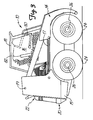
- Figure 3 is a side elevational view of a skid steer loader without front or rear attachments.
- Figure 4 is a block diagram of an auxiliary control system according to the present invention.
- FIGS 1 and 2 illustrate a skid steer loader 10 according to the present invention.
- Loader 10 includes a main frame assembly 12 which is preferably mounted to a lower frame assembly or transmission case (not shown).
- Loader 10 also includes lift arm 14, operator compartment 16 (preferably defined by a cab 18), engine compartment 20, heat exchanger compartment 22, and wheels 24 preferably mounted to main frame assembly 12 by stub axles 26.
- Figure 1 also has a portion of engine compartment 20 and heat exchanger compartment 22 cut away to reveal a portion of a rear auxiliary hydraulic circuit 28.
- Figure 2 shows a portion of a front auxiliary hydraulic circuit 30.
- Lift arm 14 is pivotably attached to upright portions 15 of main frame assembly 12 at pivot points 19.
- a pair of hydraulic actuators 17 are also coupled to lift arm 14 and main frame assembly 12. When the operator of loader 10 causes hydraulic actuators 17 to extend, lift arm 14 pivots about pivot points 19 in an upward direction. Similarly, when the operator of loader 10 operates the loader to cause hydraulic actuator 17 to retract, lift arm 14 pivots about pivot points 19 in a downward or lowered direction.
- Loader 10 in Figures 1 and 2 is depicted with both a front attachment and a rear attachment.
- the front attachment is auger 32 which is mounted to lift arm 14 by a front attachment mount 34.
- Auger 32 includes a hydraulic motor (not shown) housed in motor housing 36. Hydraulic power is preferably provided to the hydraulic motor in auger 32 through hoses 38 and 40 which are coupled to the front auxiliary hydraulic circuit 30 by hose coupling members 42.
- coupling members 42 can be placed at any suitable location on loader 10.
- the hydraulic motor located in housing 36 powers rotation of auger 32.
- the hydraulic motor located in housing 36 powers rotation of auger 32.
- the direction of rotation of auger 32 is controlled in a known manner.
- a tilt cylinder 43 is also coupled to both main frame assembly 12 and auger 32.
- Auger 32 is pivotably mounted by front mounting attachment 34 to lift arm 14. Therefore, when the operator of loader 10 causes tilt cylinder 43 to retract, this causes auger 32 to rotate relative to lift arm 14 in an upward and outward direction. Similarly, when the operator of loader 10 causes tilt cylinder 43 to extend, this causes auger 32 to rotate relative to lift arm 14 inwardly toward loader 10.
- FIG. 1 and 2 The rear mounted attachment shown in Figures 1 and 2 is a rear scarifier 44 which includes a pair of generally parallel elongate members 46 which are pivotably attached to main frame assembly 12 at pivot points 48. Scarifier 44 is also attached to uprights 15 by a pair of hydraulic cylinders 50 (i.e., linear hydraulic motors). Hydraulic cylinders 50 are controllable by the operator of loader 10 to raise and lower scarifier 44 in an arc about pivot points 48. The hydraulic fluid is provided to cylinders 50 through hoses 52 and 53 which are couplable to rear auxiliary hydraulic circuit 28 through hydraulic hose coupling members 54. Of course, coupling members 54 can be located at any suitably place on loader 10.
- hydraulic cylinders 50 i.e., linear hydraulic motors
- Hydraulic cylinders 50 are controllable by the operator of loader 10 to raise and lower scarifier 44 in an arc about pivot points 48.
- the hydraulic fluid is provided to cylinders 50 through hoses 52 and 53 which are couplable to rear
- Rear auxiliary hydraulic control circuit 28 preferably includes one or more electrically actuable control valves housed in valve housing 56.
- the control valves control the provision of hydraulic fluid to cylinders 50 through hoses 52 to accomplish desired operations (e.g., extension or retraction of cylinders 50).
- Figure 2 shows operator control handles 13R and 13L in operator compartment 16.
- Control handles 13R and 13L can be moved in a forward and rearward direction to control the speed and direction of rotation of wheels 24 in a known manner.
- Figure 3 is a side elevational view of skid steer loader 10, without front and rear attachments 32 and 44, respectively.
- Figure 3 shows that a seat 82, on which an operator sits to control skid steer loader 10, is substantially enclosed by cab 18.
- Figure 3 shows a seat bar 80 pivotally coupled to a front portion of cab 18. Typically, after the operator occupies seat 82, the operator then pivots seat bar 80 from the raised position (shown in phantom in Figure 3) to the lowered position shown in Figure 3.
- FIG. 4 is a block diagram of a control system 84 according to the present invention.
- Control system 84 includes an interlock controller 86 which includes controller 87, display 104 and watchdog timer 105.
- display 104 and watchdog timer 105 are integrated with interlock controller 86.
- Interlock controller 86 receives inputs from seat sensor 88, seat bar sensor 90, ignition switch 92, traction lock override switch 94 and traction lock switch 96.
- Ignition switch 92 is coupled to a power supply 98. Upon closing of ignition switch 92, power is supplied from power supply 98 to the remainder of the system.
- interlock controller 86 Based on the inputs received, interlock controller 86 provides two outputs to traction lockout mechanism 100, an output to hydraulic lockout mechanism 102, an output to display 104, an output to watchdog timer 105, and an output to auxiliary control circuit 106. Based on the inputs from interlock controller 86, the traction lockout mechanism 100 and hydraulic lockout mechanism 102 provide outputs to drive mechanism 108 and hydraulic circuit 110, respectively. Hydraulic circuit 110, in turn, provides an output to cylinders 17 and 43.
- interlock controller 86 with seat sensor 88, seat bar sensor 90, ignition switch 92, traction lock override switch 94 and traction switch 96, and the outputs based on those inputs, is described in detail in U.S. Patent No. 5,425,431 to Brandt et al.
- the operator is in a known occupying position (and loader 10 is in an operable state) when the seat bar 80 is down and the seat 82 is occupied. Then, when controller 86 receives a signal from seat bar sensor 90 indicating that the seat bar 80 has been raised, controller 86 provides outputs to traction lockout mechanism 100 to selectively preclude the drive mechanism 108 from driving wheels 24. Also, controller 86 provides an output to hydraulic lockout mechanism 102 causing hydraulic circuit 110 to disable certain operations of cylinders 17 and 43.
- controller 86 also provides an output signal to auxiliary control circuit 106 based on the various signals received by controller 86.
- auxiliary control circuit 106 is coupled to auxiliary operator input devices 112, auxiliary valve 114 and diverter valve 116.
- Auxiliary valve 114 in the preferred embodiment, is coupled to receive hydraulic fluid under pressure from hydraulic power circuit 118 of skid steer loader 10.
- Auxiliary valve 114 is controllable by auxiliary control circuit 106 to provide the hydraulic fluid under pressure in either a forward or a reverse direction to diverter valve 116.
- Diverter valve 116 is also controllable by auxiliary control circuit 106 and, in the preferred embodiment, diverts flow of the hydraulic fluid under pressure to either the front or rear auxiliary couplers 42,54 on skid steer loader 10.
- auxiliary control circuit 106 two auxiliary valves 114 are controlled by auxiliary control circuit 106 to provide hydraulic fluid under pressure simultaneously, and independently, to both the front and the rear auxiliary couplers 42,54 of skid steer loader 10.
- auxiliary operator input devices 112 receives an input from auxiliary operator input devices 112.
- auxiliary operator input devices 112 include push buttons or other actuable switches located on the hand grips of levers 13L and 13R, or located at another easily accessible place in the dash area of cab 18.
- the operator can operate the front or rear auxiliaries in either a momentary mode, in which hydraulic fluid under pressure is provided to the front or rear auxiliaries (as selected by the operator) only as long as the operator has the actuable switch depressed.
- the operator can also operate the front or rear auxiliaries in a detent mode in which the operator need only depress the actuable switch one time, and hydraulic fluid under pressure will be provided to the desired front or rear auxiliaries (or both) until the operator releases the detent mode by actuating the switch a second time.
- Auxiliary control circuit 106 receives the inputs from auxiliary operator input devices 112 and controller 86 and controls auxiliary valve 114 and diverter valve 116.
- auxiliary control circuit 106 corresponds to that circuit shown in the Jacobson et al. '115 patent and operates valves 114 and 116 in an on/off mode.
- auxiliary control circuit 106 provides an output to valves 114 and 116 which either causes the valves to be in the fully opened or fully closed position based on the operator inputs.
- auxiliary control circuit 106 corresponds to the controller described in copending U.S. Patent Application Serial No. 08/435,601, filed May 5, 1995, assigned to the same assignee as the present application.
- auxiliary control circuit 106 includes a microprocessor which controls the solenoids associated with the auxiliary valves in a continuous fashion using, for example, pulse width modulation or pulse frequency modulation. The valves are controlled in a variable manner between the full open and full closed position.
- auxiliary operator input devices 112 are preferably manually actuable rocker switches which are biased to a central position and which are coupled to a potentiometer.
- the microprocessor controls the solenoids based on the inputs from the potentiometer in a continuous fashion. In this way, the auxiliaries provide more smooth transitioning between full on and full off states, and also provide more smoothly controllable outputs, with finer control resolution.
- control circuit 84 During normal operation of control circuit 84, an operator enters the operator compartment 16 defined by cab 18 and occupies seat 82. The operator then lowers seat bar 80 into the lowered position shown in Figure 3. The operator then closes ignition switch 92 supplying power to the basic electrical system and to interlock controller 86 and to the remainder of the control system 84. Sensors 88 and 90 provide signals to controller 86 indicating that seat 82 is occupied and that seat bar 80 is in the lowered position. It should be noted that the signals from seat sensor 88 and seat bar sensor 90 need not be provided to controller 86 in any particular sequence. Rather, controller 86 must simply receive the signals from the appropriate sensors, regardless of the sequence, in order to allow continued operation of loader 10. In a preferred embodiment, if the seat bar is lowered before the seat is occupied, an appropriate delay, such as ten seconds is implemented before further operation is enabled.
- controller 86 Upon receiving the appropriate signals, controller 86 enables drive mechanism 108 and hydraulic circuit 110 so that the loader 10 can be moved and driven, and so that cylinders 17 and 43 can be manipulated by the operator. In addition, controller 86 allows the operator to manipulate the auxiliaries by manipulating the auxiliary operator input devices 112 without interruption.
- controller 86 provides appropriate signals to traction lockout mechanism 100 and hydraulic lockout mechanism 102 to lock out certain functions of skid steer loader 10. This is described in greater detail in the Brandt '431 patent.
- controller 86 provides a signal to auxiliary control circuit 106 indicating the status of seat sensor 88 and seat bar sensor 90.
- auxiliary control circuit 106 controls auxiliary valve 114 and diverter valve 116 accordingly.
- auxiliary control circuit 106 controls auxiliary valve 114 such that, if it is then providing hydraulic fluid under pressure to diverter valve 116, auxiliary valve 114 is moved to its closed position so that the hydraulic fluid under pressure is no longer provided to either the front or rear auxiliaries.
- auxiliary control circuit 106 is configured to receive the interrupt signal from controller 86 indicating that the seat bar 80 has been moved out of its lowered position. In response, auxiliary control circuit 106 interrupts present operation of the auxiliaries, but does not preclude future operation of the auxiliaries if the operator reactuates the auxiliary operator input device 112.
- auxiliaries it may be desirable to shut off hydraulic fluid flow to the auxiliaries if the auxiliaries are currently being operated and the operator raises seat bar 80.
- auxiliary control circuit 106 is configured to detect a signal transition provided in the interrupt signal from controller 86. Upon detecting such a transition, auxiliary control circuit 106 closes auxiliary valve 114 precluding hydraulic fluid flow to the auxiliaries. However, if the operator provides a signal through auxiliary operator input devices 112 to auxiliary control circuit 106 requesting that the operation of the auxiliaries be resumed, auxiliary control circuit 106 again opens auxiliary valve 114 and resumes operation, as usual, unless it receives another appropriate signal transition from controller 86.
- auxiliary control switch 106 is configured to only detect a transition in one direction (such as a negative going signal transition) from controller 86.
- auxiliary control circuit 106 comprises the electrical control circuit set out in the Jacobson et al. '115 patent
- a resettable mode counter is employed which has three modes of operation.
- the mode counter provides a zero output
- the auxiliaries are operable in the momentary mode only and when the mode counter provides a logical two output, the auxiliaries are operable in either the momentary or in the detent mode.
- the interrupt signal provided by controller 86 is provided to the reset input of the mode counter such that, upon receiving the positive going transition from controller 86, the mode counter is reset to zero thereby causing auxiliary valve 114 to close.
- auxiliary control circuit 106 comprises the electronic controller (or microprocessor) described in the above-mentioned copending Jacobson patent application
- the signal provided by controller 86 is simply provided to a suitable input to the electronic controller.
- the electronic controller is programmed to detect the transition of that input from a logic high level to a logic low level and close auxiliary valve 114 in response to that transition.
- auxiliary control circuit 106 is configured to resume normal operation of the auxiliaries upon receiving another request to do so from the auxiliary operator input devices 112. Further operation of the auxiliaries continues as normal unless and until another interrupt signal (in this preferred embodiment, a negative going signal transition) is received from controller 86.
- another interrupt signal in this preferred embodiment, a negative going signal transition
- the present invention provides a highly flexible system for controlling the auxiliary outputs on a power machine, such as a skid steer loader.
- the auxiliaries are preferably controlled based on a plurality of sensor inputs to an already existing interlock controller. However, in order to accommodate a wide variety of circumstances, the control signal from the controller can be overridden by the operator to accomplish continued operation of the auxiliaries.
Landscapes
- Engineering & Computer Science (AREA)
- Mining & Mineral Resources (AREA)
- Civil Engineering (AREA)
- General Engineering & Computer Science (AREA)
- Structural Engineering (AREA)
- Mechanical Engineering (AREA)
- Operation Control Of Excavators (AREA)
- Fluid-Pressure Circuits (AREA)
Applications Claiming Priority (2)
| Application Number | Priority Date | Filing Date | Title |
|---|---|---|---|
| US08/664,403 US5711391A (en) | 1996-06-17 | 1996-06-17 | Auxiliary interlock control system for power machine |
| US664403 | 1996-06-17 |
Publications (3)
| Publication Number | Publication Date |
|---|---|
| EP0814207A2 true EP0814207A2 (fr) | 1997-12-29 |
| EP0814207A3 EP0814207A3 (fr) | 1998-04-01 |
| EP0814207B1 EP0814207B1 (fr) | 2002-09-04 |
Family
ID=24665848
Family Applications (1)
| Application Number | Title | Priority Date | Filing Date |
|---|---|---|---|
| EP97109475A Expired - Lifetime EP0814207B1 (fr) | 1996-06-17 | 1997-06-11 | Système de commande de verrouillage auxiliaire pour machine motrice |
Country Status (8)
| Country | Link |
|---|---|
| US (1) | US5711391A (fr) |
| EP (1) | EP0814207B1 (fr) |
| JP (1) | JPH1077662A (fr) |
| KR (1) | KR980001107A (fr) |
| AU (1) | AU717010B2 (fr) |
| BR (1) | BR9703594A (fr) |
| CA (1) | CA2204075C (fr) |
| DE (1) | DE69715103T2 (fr) |
Cited By (6)
| Publication number | Priority date | Publication date | Assignee | Title |
|---|---|---|---|---|
| KR980001107A (ko) * | 1996-06-17 | 1998-03-30 | 찰스 알. 호지 | 동력 기계용 연동 제어 장치 |
| EP0978406A3 (fr) * | 1998-08-07 | 2001-11-28 | Clark Equipment Company | Télécommande pour un outil de travail d'un véhicule utilitaire |
| US6923285B1 (en) | 2000-02-01 | 2005-08-02 | Clark Equipment Company | Attachment control device |
| EP1259937A4 (fr) * | 1999-04-23 | 2006-05-24 | Clark Equipment Co | Caracteristiques d'un ordinateur central de commande pour une machine motrice |
| WO2007097862A1 (fr) * | 2006-02-24 | 2007-08-30 | Caterpillar Inc. | Engin de terrassement avec fonction de détection de la présence de l'opérateur |
| CN102864809A (zh) * | 2012-10-22 | 2013-01-09 | 三一重机有限公司 | 一种液压先导控制系统及工程机械 |
Families Citing this family (24)
| Publication number | Priority date | Publication date | Assignee | Title |
|---|---|---|---|---|
| US5934051A (en) * | 1997-02-06 | 1999-08-10 | Textron, Inc. | Solid state mow system for electrically powered mower |
| US6062331A (en) * | 1998-10-09 | 2000-05-16 | S.A.R.L. | Auxiliary hydraulic control system for a work machine |
| US6186260B1 (en) | 1998-10-09 | 2001-02-13 | Caterpillar S.A.R.L. | Arm rest/seat switch circuit configuration for use as an operational state sensor for a work machine |
| US6135230A (en) * | 1998-10-09 | 2000-10-24 | Caterpillar S.A.R.L. | Interlock control system for a work machine |
| US6189646B1 (en) * | 1998-11-30 | 2001-02-20 | Clark Equipment Company | Traction lock/momentary override |
| US6416112B1 (en) * | 2000-08-03 | 2002-07-09 | Equipment Shield, A Division Of Trivits Companies, Llc. | Protective shield for off-road vehicles |
| USD463454S1 (en) | 2000-12-11 | 2002-09-24 | Finn Corporation | Skid loader |
| US6765310B1 (en) | 2001-05-07 | 2004-07-20 | Multicraft International | Programmed virtual multi-pole or multi-throw switch for outdoor power equipment and method |
| US6843340B2 (en) | 2001-07-20 | 2005-01-18 | Finn Corporation | Hydraulic apparatus for vehicles |
| US6948398B2 (en) | 2002-07-22 | 2005-09-27 | Deere & Company | Joystick with enabling sensors |
| JP3953382B2 (ja) * | 2002-08-06 | 2007-08-08 | 株式会社クボタ | 作業機のエンジン自動停止解除構造 |
| US20060053926A1 (en) * | 2004-08-24 | 2006-03-16 | Vermeer Manufacturing Company | Apparatus and method for speed control |
| US7192100B2 (en) * | 2004-09-27 | 2007-03-20 | Clark Equipment Company | Power machine having traction lock with speed-range selector |
| US7392113B2 (en) * | 2005-02-08 | 2008-06-24 | Halliburton Energy Services, Inc. | Systems for controlling multiple actuators |
| US7546730B2 (en) * | 2006-03-23 | 2009-06-16 | Parker-Hannifin Corporation | Hydraulic vehicle stabilizer system with two-stage bi-rotational hydraulic pump system |
| EP2201184A1 (fr) * | 2007-09-24 | 2010-06-30 | Clark Equipment Company | Système de régulation de débit hydraulique auxiliaire pour un petit chargeur |
| EP2565653B1 (fr) * | 2011-09-05 | 2019-05-08 | Fluke Corporation | Unité de surveillance pour détecteur de tension avec affichage déclenchant avertissement visuel |
| WO2014160189A2 (fr) * | 2013-03-14 | 2014-10-02 | Diversified Products, LLC | Système d'énergie mobile auxiliaire et accessoire formant râtelier à outils |
| US10336292B2 (en) | 2016-08-30 | 2019-07-02 | Clark Equipment Company | Seat belt |
| JP6761102B2 (ja) * | 2017-02-22 | 2020-09-23 | 住友建機株式会社 | ショベル |
| US11001988B2 (en) * | 2018-06-18 | 2021-05-11 | Caterpillar Inc. | Controlling interlocks based on an interlock configuration |
| US12173478B2 (en) * | 2020-09-01 | 2024-12-24 | Hitachi Construction Machinery Co., Ltd. | Control system for work machine |
| US12227145B2 (en) * | 2023-01-20 | 2025-02-18 | Caterpillar Inc. | Machine security system |
| USD1104077S1 (en) | 2023-10-31 | 2025-12-02 | Caterpillar Inc. | Machine linkage |
Citations (5)
| Publication number | Priority date | Publication date | Assignee | Title |
|---|---|---|---|---|
| US4389154A (en) | 1981-05-13 | 1983-06-21 | Sperry Corporation | Time delay for a seat switch activated loader boom lock |
| US4955452A (en) | 1989-04-20 | 1990-09-11 | Trak International, Inc. | Locking apparatus for skid steer loader |
| US5174115A (en) | 1991-09-30 | 1992-12-29 | Clark Equipment Company | Electrically actuated and controlled auxiliary hydraulic system for skid steer loader |
| US5425431A (en) | 1994-02-18 | 1995-06-20 | Clark Equipment Company | Interlock control system for power machine |
| US5590731A (en) | 1995-05-05 | 1997-01-07 | Clark Equipment Company | Hydraulic control system providing proportional movement to an attachment of a power machine |
Family Cites Families (17)
| Publication number | Priority date | Publication date | Assignee | Title |
|---|---|---|---|---|
| US4162714A (en) * | 1978-03-15 | 1979-07-31 | Correll Richard R | Safety interlock system for fire truck pump throttle control |
| US4392543A (en) * | 1981-02-26 | 1983-07-12 | The Murray Ohio Manufacturing Co. | Hydrostatic transmission control |
| US4699561A (en) * | 1986-05-08 | 1987-10-13 | J. I. Case Company | Engine interlock control system for a material handling implement |
| US4844685A (en) * | 1986-09-03 | 1989-07-04 | Clark Equipment Company | Electronic bucket positioning and control system |
| JPH01192921A (ja) * | 1988-01-27 | 1989-08-03 | Caterpillar Inc | 建設機械の作業機位置制御装置 |
| US4844196A (en) * | 1988-02-10 | 1989-07-04 | Ford New Holland, Inc. | Seat belt interlock for loaders |
| US4856612A (en) * | 1988-02-10 | 1989-08-15 | Ford New Holland, Inc. | Method of controlling the operation of a loader |
| US4871044A (en) * | 1988-02-10 | 1989-10-03 | Ford New Holland, Inc. | Service override for loader interlock |
| CA1336203C (fr) * | 1988-07-27 | 1995-07-04 | Joseph M. Mather | Systeme hydraulique auxiliaire a commande electrique pour chargeur a direction differentielle |
| US5178510A (en) * | 1988-08-02 | 1993-01-12 | Kabushiki Kaisha Komatsu Seisakusho | Apparatus for controlling the hydraulic cylinder of a power shovel |
| US5205181A (en) * | 1992-02-03 | 1993-04-27 | Vermeer Manufacturing Company | Manual motion control override apparatus |
| US5203440A (en) * | 1992-06-24 | 1993-04-20 | Deere & Company | Interlock circuit for a vehicle with an optical second drive |
| JPH06199146A (ja) * | 1992-11-12 | 1994-07-19 | Honda Motor Co Ltd | 電動車の制御装置 |
| US5577876A (en) * | 1994-02-22 | 1996-11-26 | Clark Equipment Company | Hydraulic interblock system |
| DE69506594T2 (de) * | 1994-02-18 | 1999-04-29 | Clark Equipment Co., Woodcliff Lake, N.J. | Hall-Sensoranordnung |
| KR960029557A (ko) * | 1995-01-28 | 1996-08-17 | 유상부 | 유압식 굴삭기의 제어장치 및 방법 |
| US5711391A (en) * | 1996-06-17 | 1998-01-27 | Clark Equipment Company | Auxiliary interlock control system for power machine |
-
1996
- 1996-06-17 US US08/664,403 patent/US5711391A/en not_active Expired - Lifetime
-
1997
- 1997-04-16 AU AU17898/97A patent/AU717010B2/en not_active Ceased
- 1997-04-30 CA CA002204075A patent/CA2204075C/fr not_active Expired - Fee Related
- 1997-06-03 KR KR1019970022792A patent/KR980001107A/ko not_active Ceased
- 1997-06-11 DE DE69715103T patent/DE69715103T2/de not_active Expired - Lifetime
- 1997-06-11 EP EP97109475A patent/EP0814207B1/fr not_active Expired - Lifetime
- 1997-06-13 JP JP9156213A patent/JPH1077662A/ja active Pending
- 1997-06-16 BR BR9703594A patent/BR9703594A/pt not_active IP Right Cessation
Patent Citations (5)
| Publication number | Priority date | Publication date | Assignee | Title |
|---|---|---|---|---|
| US4389154A (en) | 1981-05-13 | 1983-06-21 | Sperry Corporation | Time delay for a seat switch activated loader boom lock |
| US4955452A (en) | 1989-04-20 | 1990-09-11 | Trak International, Inc. | Locking apparatus for skid steer loader |
| US5174115A (en) | 1991-09-30 | 1992-12-29 | Clark Equipment Company | Electrically actuated and controlled auxiliary hydraulic system for skid steer loader |
| US5425431A (en) | 1994-02-18 | 1995-06-20 | Clark Equipment Company | Interlock control system for power machine |
| US5590731A (en) | 1995-05-05 | 1997-01-07 | Clark Equipment Company | Hydraulic control system providing proportional movement to an attachment of a power machine |
Cited By (7)
| Publication number | Priority date | Publication date | Assignee | Title |
|---|---|---|---|---|
| KR980001107A (ko) * | 1996-06-17 | 1998-03-30 | 찰스 알. 호지 | 동력 기계용 연동 제어 장치 |
| EP0978406A3 (fr) * | 1998-08-07 | 2001-11-28 | Clark Equipment Company | Télécommande pour un outil de travail d'un véhicule utilitaire |
| EP1259937A4 (fr) * | 1999-04-23 | 2006-05-24 | Clark Equipment Co | Caracteristiques d'un ordinateur central de commande pour une machine motrice |
| US6923285B1 (en) | 2000-02-01 | 2005-08-02 | Clark Equipment Company | Attachment control device |
| WO2007097862A1 (fr) * | 2006-02-24 | 2007-08-30 | Caterpillar Inc. | Engin de terrassement avec fonction de détection de la présence de l'opérateur |
| US7899597B2 (en) | 2006-02-24 | 2011-03-01 | Caterpillar Inc. | Work machine with operator presence detection strategy |
| CN102864809A (zh) * | 2012-10-22 | 2013-01-09 | 三一重机有限公司 | 一种液压先导控制系统及工程机械 |
Also Published As
| Publication number | Publication date |
|---|---|
| BR9703594A (pt) | 1998-09-22 |
| AU717010B2 (en) | 2000-03-16 |
| JPH1077662A (ja) | 1998-03-24 |
| DE69715103D1 (de) | 2002-10-10 |
| US5711391A (en) | 1998-01-27 |
| KR980001107A (ko) | 1998-03-30 |
| EP0814207B1 (fr) | 2002-09-04 |
| DE69715103T2 (de) | 2003-04-30 |
| CA2204075C (fr) | 2005-06-21 |
| CA2204075A1 (fr) | 1997-12-17 |
| EP0814207A3 (fr) | 1998-04-01 |
| AU1789897A (en) | 1998-01-08 |
Similar Documents
| Publication | Publication Date | Title |
|---|---|---|
| US5711391A (en) | Auxiliary interlock control system for power machine | |
| EP0741209B1 (fr) | Circuit amovible fournissant un signal indicatif d'un outil amovible à une commande électronique | |
| EP0978406B1 (fr) | Télécommande pour un outil de travail d'un véhicule utilitaire | |
| US6923285B1 (en) | Attachment control device | |
| US5957213A (en) | Intelligent attachment to a power tool | |
| EP2134905B1 (fr) | Systeme de gestion de puissance hydraulique | |
| US5713419A (en) | Intelligent attachment to a power tool | |
| WO2009088462A1 (fr) | Dispositif de commande d'accessoire | |
| EP0285281B1 (fr) | Dispositif de sécurité pour un engin autopropulseur muni de stabilisateurs, notamment pour un engin de travaux publics du type pelleteuse | |
| EP1006016B1 (fr) | Verrouillage de traction et unité de déclenchement | |
| US6062331A (en) | Auxiliary hydraulic control system for a work machine | |
| US5822960A (en) | Reel mower | |
| EP0668194B1 (fr) | Assemblage d'un capteur à effet hall | |
| JPH0411128A (ja) | バックホウの制御装置 | |
| AU700677B2 (en) | Interlock control system for power machine | |
| JP2000303498A (ja) | 建設機械 | |
| JP2597438Y2 (ja) | 運転室移動式ホイ−ルクレ−ンにおける安全装置 | |
| JPH0324934B2 (fr) | ||
| JPH05306535A (ja) | バックホウ |
Legal Events
| Date | Code | Title | Description |
|---|---|---|---|
| PUAI | Public reference made under article 153(3) epc to a published international application that has entered the european phase |
Free format text: ORIGINAL CODE: 0009012 |
|
| AK | Designated contracting states |
Kind code of ref document: A2 Designated state(s): BE DE FR GB IT |
|
| PUAL | Search report despatched |
Free format text: ORIGINAL CODE: 0009013 |
|
| AK | Designated contracting states |
Kind code of ref document: A3 Designated state(s): AT BE CH DE DK ES FI FR GB GR IE IT LI LU MC NL PT SE |
|
| 17P | Request for examination filed |
Effective date: 19980715 |
|
| AKX | Designation fees paid | ||
| RBV | Designated contracting states (corrected) | ||
| RBV | Designated contracting states (corrected) |
Designated state(s): BE DE FR GB IT |
|
| GRAG | Despatch of communication of intention to grant |
Free format text: ORIGINAL CODE: EPIDOS AGRA |
|
| 17Q | First examination report despatched |
Effective date: 20010529 |
|
| GRAG | Despatch of communication of intention to grant |
Free format text: ORIGINAL CODE: EPIDOS AGRA |
|
| GRAG | Despatch of communication of intention to grant |
Free format text: ORIGINAL CODE: EPIDOS AGRA |
|
| GRAH | Despatch of communication of intention to grant a patent |
Free format text: ORIGINAL CODE: EPIDOS IGRA |
|
| GRAH | Despatch of communication of intention to grant a patent |
Free format text: ORIGINAL CODE: EPIDOS IGRA |
|
| GRAA | (expected) grant |
Free format text: ORIGINAL CODE: 0009210 |
|
| AK | Designated contracting states |
Kind code of ref document: B1 Designated state(s): BE DE FR GB IT |
|
| REG | Reference to a national code |
Ref country code: GB Ref legal event code: FG4D |
|
| REF | Corresponds to: |
Ref document number: 69715103 Country of ref document: DE Date of ref document: 20021010 |
|
| ET | Fr: translation filed | ||
| PLBE | No opposition filed within time limit |
Free format text: ORIGINAL CODE: 0009261 |
|
| STAA | Information on the status of an ep patent application or granted ep patent |
Free format text: STATUS: NO OPPOSITION FILED WITHIN TIME LIMIT |
|
| PGFP | Annual fee paid to national office [announced via postgrant information from national office to epo] |
Ref country code: BE Payment date: 20030724 Year of fee payment: 7 |
|
| 26N | No opposition filed |
Effective date: 20030605 |
|
| PG25 | Lapsed in a contracting state [announced via postgrant information from national office to epo] |
Ref country code: BE Free format text: LAPSE BECAUSE OF NON-PAYMENT OF DUE FEES Effective date: 20040630 |
|
| BERE | Be: lapsed |
Owner name: *CLARK EQUIPMENT CY Effective date: 20040630 |
|
| PGFP | Annual fee paid to national office [announced via postgrant information from national office to epo] |
Ref country code: GB Payment date: 20100625 Year of fee payment: 14 |
|
| GBPC | Gb: european patent ceased through non-payment of renewal fee |
Effective date: 20110611 |
|
| PG25 | Lapsed in a contracting state [announced via postgrant information from national office to epo] |
Ref country code: GB Free format text: LAPSE BECAUSE OF NON-PAYMENT OF DUE FEES Effective date: 20110611 |
|
| REG | Reference to a national code |
Ref country code: FR Ref legal event code: PLFP Year of fee payment: 20 |
|
| PGFP | Annual fee paid to national office [announced via postgrant information from national office to epo] |
Ref country code: FR Payment date: 20160628 Year of fee payment: 20 |
|
| PGFP | Annual fee paid to national office [announced via postgrant information from national office to epo] |
Ref country code: IT Payment date: 20160627 Year of fee payment: 20 Ref country code: DE Payment date: 20160628 Year of fee payment: 20 |
|
| REG | Reference to a national code |
Ref country code: DE Ref legal event code: R071 Ref document number: 69715103 Country of ref document: DE |