EP0814221A1 - Verfahren zur Herstellung eines Betonmastes, Vorrichtung zur Durchführung des Verfahrens und damit hergestellter Mast - Google Patents
Verfahren zur Herstellung eines Betonmastes, Vorrichtung zur Durchführung des Verfahrens und damit hergestellter Mast Download PDFInfo
- Publication number
- EP0814221A1 EP0814221A1 EP97109519A EP97109519A EP0814221A1 EP 0814221 A1 EP0814221 A1 EP 0814221A1 EP 97109519 A EP97109519 A EP 97109519A EP 97109519 A EP97109519 A EP 97109519A EP 0814221 A1 EP0814221 A1 EP 0814221A1
- Authority
- EP
- European Patent Office
- Prior art keywords
- mold
- elements
- concrete
- mast
- flanges
- Prior art date
- Legal status (The legal status is an assumption and is not a legal conclusion. Google has not performed a legal analysis and makes no representation as to the accuracy of the status listed.)
- Granted
Links
- 239000004567 concrete Substances 0.000 title claims abstract description 30
- 238000000034 method Methods 0.000 title claims abstract description 21
- 230000002787 reinforcement Effects 0.000 claims description 14
- 238000000605 extraction Methods 0.000 claims description 12
- 238000005119 centrifugation Methods 0.000 claims description 11
- 239000002184 metal Substances 0.000 claims description 11
- 238000004519 manufacturing process Methods 0.000 claims description 8
- 230000008878 coupling Effects 0.000 claims description 6
- 238000010168 coupling process Methods 0.000 claims description 6
- 238000005859 coupling reaction Methods 0.000 claims description 6
- 238000009415 formwork Methods 0.000 claims description 4
- 239000000463 material Substances 0.000 claims description 4
- 230000001464 adherent effect Effects 0.000 claims description 3
- 238000003754 machining Methods 0.000 claims description 2
- 239000011150 reinforced concrete Substances 0.000 claims 3
- 230000003014 reinforcing effect Effects 0.000 abstract 2
- 238000005266 casting Methods 0.000 abstract 1
- 239000004570 mortar (masonry) Substances 0.000 abstract 1
- 238000009416 shuttering Methods 0.000 abstract 1
- 239000011178 precast concrete Substances 0.000 description 3
- 238000005452 bending Methods 0.000 description 2
- 230000005540 biological transmission Effects 0.000 description 2
- 238000002347 injection Methods 0.000 description 2
- 239000007924 injection Substances 0.000 description 2
- 238000010521 absorption reaction Methods 0.000 description 1
- 230000007547 defect Effects 0.000 description 1
- 238000010008 shearing Methods 0.000 description 1
- 238000003860 storage Methods 0.000 description 1
- 239000011800 void material Substances 0.000 description 1
- 238000003466 welding Methods 0.000 description 1
Images


Classifications
-
- E—FIXED CONSTRUCTIONS
- E04—BUILDING
- E04H—BUILDINGS OR LIKE STRUCTURES FOR PARTICULAR PURPOSES; SWIMMING OR SPLASH BATHS OR POOLS; MASTS; FENCING; TENTS OR CANOPIES, IN GENERAL
- E04H12/00—Towers; Masts or poles; Chimney stacks; Water-towers; Methods of erecting such structures
- E04H12/16—Prestressed structures
-
- B—PERFORMING OPERATIONS; TRANSPORTING
- B28—WORKING CEMENT, CLAY, OR STONE
- B28B—SHAPING CLAY OR OTHER CERAMIC COMPOSITIONS; SHAPING SLAG; SHAPING MIXTURES CONTAINING CEMENTITIOUS MATERIAL, e.g. PLASTER
- B28B13/00—Feeding the unshaped material to moulds or apparatus for producing shaped articles; Discharging shaped articles from such moulds or apparatus
- B28B13/04—Discharging the shaped articles
- B28B13/06—Removing the shaped articles from moulds
-
- B—PERFORMING OPERATIONS; TRANSPORTING
- B28—WORKING CEMENT, CLAY, OR STONE
- B28B—SHAPING CLAY OR OTHER CERAMIC COMPOSITIONS; SHAPING SLAG; SHAPING MIXTURES CONTAINING CEMENTITIOUS MATERIAL, e.g. PLASTER
- B28B23/00—Arrangements specially adapted for the production of shaped articles with elements wholly or partly embedded in the moulding material; Production of reinforced objects
- B28B23/02—Arrangements specially adapted for the production of shaped articles with elements wholly or partly embedded in the moulding material; Production of reinforced objects wherein the elements are reinforcing members
- B28B23/18—Arrangements specially adapted for the production of shaped articles with elements wholly or partly embedded in the moulding material; Production of reinforced objects wherein the elements are reinforcing members for the production of elongated articles
-
- E—FIXED CONSTRUCTIONS
- E04—BUILDING
- E04H—BUILDINGS OR LIKE STRUCTURES FOR PARTICULAR PURPOSES; SWIMMING OR SPLASH BATHS OR POOLS; MASTS; FENCING; TENTS OR CANOPIES, IN GENERAL
- E04H12/00—Towers; Masts or poles; Chimney stacks; Water-towers; Methods of erecting such structures
- E04H12/02—Structures made of specified materials
- E04H12/12—Structures made of specified materials of concrete or other stone-like material, with or without internal or external reinforcements, e.g. with metal coverings, with permanent form elements
Definitions
- the subject of the present invention is a method for manufacturing concrete masts and a device for implementing this method.
- This invention also relates to concrete masts directly obtained by the implementation of said method.
- This method is particularly suitable for the manufacture of masts of a considerable length which cannot be manufactured in a single part, or of masts which, because of constraints inherent in their transport or their storage, must be made of several elements.
- Masts are known comprising at one of their ends a female cone intended to receive a male cone from one end of another mast, these cones being of corresponding precise dimensions so that, during the introduction of the male cone d 'an element in the female cone of another element, we obtain an assembly with the least play possible.
- the angle at the top of the cone is chosen to make a self-locking coupling.
- This technique which requires high dimensional precision of the male and female cones of the elements, can only be used, for precast concrete elements by centrifugation, if these cones are produced beforehand in precise molds and then incorporated into the structural element during its centrifugation. It is indeed impossible to obtain cones, and in particular female cones having the dimensional precision required by centrifugation.
- This technique because of the precision required, is too expensive for the production of precast concrete masts by centrifugation. It also has the disadvantage of requiring the welding of the metal reinforcements of the mast to those of the cone when the latter are put in place.
- Another technique for producing concrete masts either by centrifugation or by vibration on a vibrating table consists in using metal cones, respectively male and female, at the ends of the elements of the mast. These metal cones act as a lost mold and remain integrated into the elements constituting the mast after its manufacture and coupling. To reduce the production costs of such masts, these metal cones were made from rolled sheets with the disadvantage that these cones are not very precise. The two added elements are in contact with the joint and due to the imprecision it is necessary to fill the space between the female cone and the male cone by injecting concrete or any other curable material in order to guarantee the good transmission of the forces of bending and twisting.
- the object of the present invention is to obviate the drawbacks mentioned above and to offer a method of manufacturing structural elements for making concrete masts both by centrifugation and by vibration which does not require a lost mold and which allows a coupling of the different elements of the precise mast, without play and therefore without injection during assembly and which is capable of effectively transmitting the bending and shearing forces and twist.
- Another object of the invention relates to a device allowing the implementation of the method cited above and which is distinguished by the characteristics listed in claim 6.
- the invention also relates to the precast concrete masts directly obtained by said process.
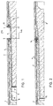
- Figure 1 illustrates two elements 1,2 shuttered and put in place on a bench to be concreted.
- Element 1 will be referenced as the female element and element 2 as the male element.
- the length of each element 1, 2 can be, for example, around twenty meters and their section can be circular, oval, elliptical or polygonal. To reduce the weight of these elements, they are generally hollow.
- the body of the elements 1,2 is in the form of a prismatic or cylindrical concrete tube which can be provided with longitudinal 3 and transverse 4 metallic reinforcements closed on themselves in order to reinforce the elements 1,2.
- a metal mold 5 in one piece is put in place before concreting between the two elements 1,2 of the mast. This mold 5 is in the form of a truncated cone closed at one of its ends.
- Two annular flanges 6,7 are arranged near the open end of the mold 5. These flanges 6,7 are directed outwards perpendicular to the axis of revolution of the truncated cone. At its opposite end, the mold 5 is closed by a bottom 8.
- a second disc 9 acts as a double bottom. The bottom of the mold 8 and the disc 9 are spaced apart by a distance substantially equivalent to that separating the two flanges 6,7 in the longitudinal direction. It is obvious that the double bottom of the mold can be produced in different ways such as for example being made up of the bottom 8 and of a plug made of a suitable material such as SAGEX (registered trademark) for example which would fill the space shown in the drawing between the bottom 8 and the disc 9.
- the flanges 6,7 are provided with holes distributed at regular intervals around their periphery. These holes 10 cooperate on the one hand with angular positioning devices of the two elements 1,2 of the mast and on the other hand with extraction devices to facilitate extraction of the mold after placing the concrete.
- FIG. 3 shows eight holes 10 distributed every 45 degrees cooperating with four angular positioning devices and four extraction devices distributed alternately around the periphery of the flange 7.
- the angular positioning device illustrated on a larger scale in Figure 4, consists of an assembly socket 11 communicating with the hole 10 and secured to a plate 12 bearing against the surface of the flanges 6,7 located towards the inside of the elements bodies 1,2.
- the ends of the longitudinal metal reinforcements 3 are welded against the external surface of the sockets 11.
- the socket 11 On the side of the female element 1, the socket 11 is extended by a formwork making it possible to provide a recess 13 in the body of the element 1.
- FIG. 2 illustrates the two elements 1, 2 of the mast after the placing of the concrete and after the mold 5 has been removed by means of the extraction devices, the operation of which will be explained below.
- the outer surface of the cone of the male element 2 comes into contact with the inner surface of the female cone of the element.
- the mold 5 is dimensioned and in particular the distance between the two flanges 6,7 so that the end of the male cone of the element 2 does not come into contact with the bottom of the female cone of the element 1 while the plates 12 ending the edge of the cones are also not in contact.
- the fact that these surfaces do not touch, once the elements have been assembled, prevents the perpendicularity of these surfaces from the axis of the cone has an influence on the alignment of the elements (1,2).
- the space remaining between these two annular surfaces 12 can be filled with a hard mass which will increase the compressed surface at this level.
- the angle of the cone is preferably minimum to facilitate the extraction of the mold 5, but can be chosen so that the assembly is self-locking.
- d m / sin ( ⁇ ) is an approximation and must be adjusted according to possible inaccuracies of the mold.
- Positioning studs 14 are housed in the sockets 11 thereby ensuring perfect angular positioning of the elements 1 and 2.
- the mold 5 is made of rolled sheets and therefore is not very precise. This fact, instead of being a drawback as in the case of a two-part mold, promotes the resumption of the torsional forces to which the mast is subjected. Indeed, the fact that the section of the conical mold 5 is not perfectly round promotes the absorption of torsional forces, the defects on one side of the mold being found on the other. It should be noted that this fact can be promoted by giving the section of the mold 5 a slightly oval or elliptical shape. It is also possible to produce the mold 5 by precise machining in a metal or plastic part.
- FIG. 5 illustrates the detail of the extraction devices located on the periphery of the flanges 6, 7 alternating with the positioning devices. They consist of a nut 15 welded to the external surface of the flanges 6,7. A bolt 16 bears in the service position against the stop plates 12 located on the annular surfaces of the male and female cones. When the concrete has been placed and set, it suffices to screw the bolts 16 to move the mold 5 away from the cones thus obtained.
- the bolts 16 cooperating with the nuts 15 can be replaced by hydraulic cylinders.
- FIG. 6 illustrates the positioning devices in the case of a mast comprising prestressing reinforcements 17. These prestressing reinforcements are as illustrated in the drawing, anchored at each end of the mast and tensioned. In this case, the flanges 6,7 have additional holes allowing the passage of these frames 17. It is also possible to provide that these prestressing frames 17 are anchored using a mechanical device provided on the stop plates and tensioned at each end of the mast .
- the method of manufacturing a concrete mast comprises the following steps. First of all, it involves placing the formwork on a concreting bench of at least two elements constituting the mast. It is obvious that, depending on the total length of the mast, more than two elements may be necessary to obtain the desired length.
- a metal mold is positioned in one piece at the junction of two elements. This mold is in the form of a truncated cone open at one of its ends and has a bottom 8 at the other end. At its open end, the mold has two annular flanges 6,7 parallel and substantially perpendicular to its axis of revolution. The mold also has a disc 9 parallel to the bottom 8 which acts as a double bottom.
- the longitudinal distance separating the bottom 8 of the disc 9 is slightly greater than the longitudinal spacing of the flanges 6,7.
- the distance between the two flanges 6,7 which depends on the thickness of the mold as well as the opening angle of the cone, is determined so that, once placed one on the other, the two elements s' fit together perfectly and come into contact only through their conical surfaces. Once the elements are in place as described above, the concrete is put in place.
- This concrete placement can be done in two different ways. We can first put the concrete in place by vibration by placing the bench on a vibrating table for example. Once the concrete has been poured, it suffices to remove the mold 5 by acting on the extraction devices arranged on the flanges 6,7 of the mold 5.
- the two elements are coupled 1,2 thus obtained.
- the fact of using a one-piece mold provided with positioning devices guarantees that the male cone of element 2 will adapt perfectly to the female cone receiving it from element 1, thereby allowing correct transmission of forces. of flexion and torsion.
- the concrete can be placed by centrifugation. In the case of concreting by centrifugation, an additional step is necessary before the extraction of the mold 5. Indeed during centrifugation there will be created a vacuum located between the outer surface of the conical mold 5 and the female cone. This void will be filled before removing the mold by injecting concrete or any other material which can be hardened by two injection holes made in the body of the female element 1.
- the prestressing reinforcements can be produced by the technique of adherent wires, these wires then being linked to the concrete, or by strands at the terminals which, once energized, are coupled to the ends of the mast portions, for example to the stop plates 12 .
Landscapes
- Engineering & Computer Science (AREA)
- Architecture (AREA)
- Ceramic Engineering (AREA)
- Chemical & Material Sciences (AREA)
- Structural Engineering (AREA)
- Manufacturing & Machinery (AREA)
- Civil Engineering (AREA)
- Mechanical Engineering (AREA)
- Life Sciences & Earth Sciences (AREA)
- Materials Engineering (AREA)
- Wood Science & Technology (AREA)
- Manufacturing Of Tubular Articles Or Embedded Moulded Articles (AREA)
- Moulds, Cores, Or Mandrels (AREA)
- On-Site Construction Work That Accompanies The Preparation And Application Of Concrete (AREA)
- Devices For Post-Treatments, Processing, Supply, Discharge, And Other Processes (AREA)
Applications Claiming Priority (3)
| Application Number | Priority Date | Filing Date | Title |
|---|---|---|---|
| CH1554/96 | 1996-06-21 | ||
| CH01554/96A CH691234A5 (fr) | 1996-06-21 | 1996-06-21 | Procédé de fabrication d'un mât en béton, dispositif pour la mise en oeuvre de ce procédé et mât obtenu par ce procédé. |
| CH155496 | 1996-06-21 |
Publications (2)
| Publication Number | Publication Date |
|---|---|
| EP0814221A1 true EP0814221A1 (de) | 1997-12-29 |
| EP0814221B1 EP0814221B1 (de) | 2002-09-18 |
Family
ID=4213136
Family Applications (1)
| Application Number | Title | Priority Date | Filing Date |
|---|---|---|---|
| EP97109519A Expired - Lifetime EP0814221B1 (de) | 1996-06-21 | 1997-06-12 | Verfahren zur Herstellung eines Betonmastes, Vorrichtung zur Durchführung des Verfahrens und damit hergestellter Mast |
Country Status (6)
| Country | Link |
|---|---|
| EP (1) | EP0814221B1 (de) |
| AT (1) | ATE224495T1 (de) |
| CH (1) | CH691234A5 (de) |
| DE (1) | DE69715524T2 (de) |
| DK (1) | DK0814221T3 (de) |
| ES (1) | ES2180856T3 (de) |
Families Citing this family (2)
| Publication number | Priority date | Publication date | Assignee | Title |
|---|---|---|---|---|
| ES2291053B1 (es) * | 2003-10-07 | 2009-03-01 | Romero Hormelec, S.A. | Sistema de fabricacion y union de tramos de postes huecos de hormigon armado y/o pretensado. |
| DE102006030400A1 (de) * | 2006-06-29 | 2008-01-03 | Pfleiderer Europoles Gmbh & Co. Kg | Freileitungsmast aus Schleuderbeton |
Citations (3)
| Publication number | Priority date | Publication date | Assignee | Title |
|---|---|---|---|---|
| GB386108A (en) * | 1931-12-21 | 1933-01-12 | Pfistershammer Josef | Reinforced concrete pole |
| DE1434730A1 (de) * | 1963-11-12 | 1970-01-15 | Moll Kg Leonhard | Verfahren zur Herstellung von aus mehreren loesbar miteinander verbundenen Teilen bestehenden Stahl- oder Spannbetonmasten und nach diesem Verfahren hergestellter mehrteiliger Betonmast |
| FR2367158A1 (fr) * | 1976-10-05 | 1978-05-05 | Gram Sa | Dispositif d'accouplement pour element en beton arme ou precontraint |
-
1996
- 1996-06-21 CH CH01554/96A patent/CH691234A5/fr not_active IP Right Cessation
-
1997
- 1997-06-12 AT AT97109519T patent/ATE224495T1/de not_active IP Right Cessation
- 1997-06-12 EP EP97109519A patent/EP0814221B1/de not_active Expired - Lifetime
- 1997-06-12 DK DK97109519T patent/DK0814221T3/da active
- 1997-06-12 DE DE69715524T patent/DE69715524T2/de not_active Expired - Fee Related
- 1997-06-12 ES ES97109519T patent/ES2180856T3/es not_active Expired - Lifetime
Patent Citations (3)
| Publication number | Priority date | Publication date | Assignee | Title |
|---|---|---|---|---|
| GB386108A (en) * | 1931-12-21 | 1933-01-12 | Pfistershammer Josef | Reinforced concrete pole |
| DE1434730A1 (de) * | 1963-11-12 | 1970-01-15 | Moll Kg Leonhard | Verfahren zur Herstellung von aus mehreren loesbar miteinander verbundenen Teilen bestehenden Stahl- oder Spannbetonmasten und nach diesem Verfahren hergestellter mehrteiliger Betonmast |
| FR2367158A1 (fr) * | 1976-10-05 | 1978-05-05 | Gram Sa | Dispositif d'accouplement pour element en beton arme ou precontraint |
Also Published As
| Publication number | Publication date |
|---|---|
| DE69715524T2 (de) | 2003-05-22 |
| ATE224495T1 (de) | 2002-10-15 |
| EP0814221B1 (de) | 2002-09-18 |
| CH691234A5 (fr) | 2001-05-31 |
| ES2180856T3 (es) | 2003-02-16 |
| DK0814221T3 (da) | 2003-01-27 |
| DE69715524D1 (de) | 2002-10-24 |
Similar Documents
| Publication | Publication Date | Title |
|---|---|---|
| EP2140459B1 (de) | Container zum transportieren und/oder lagern von kernmaterialien mit einer aus auf eine metallverstärkung gegossenem blei hergestellten radiologischen abschirmung | |
| WO1995025864A1 (fr) | Panneau pour la realisation de bassins de retention | |
| FR3002956A1 (fr) | Paroi moulee precontrainte et procede de realisation d'une telle paroi | |
| FR2956871A1 (fr) | Procede et outillage pour la realisation in situ d'un mur sandwich comportant deux parois en beton separees par un panneau isolant | |
| EP0814221B1 (de) | Verfahren zur Herstellung eines Betonmastes, Vorrichtung zur Durchführung des Verfahrens und damit hergestellter Mast | |
| WO2000044993A1 (fr) | Conduite de circulation de fluide sous pression et procede de realisation d'une telle conduite | |
| CH677250A5 (de) | ||
| EP1956156B1 (de) | Anschluss zur Verbindung von zwei Platten einer Mauer mit verlorener Verschalung | |
| FR3043417A1 (fr) | Element-cadre prefabrique et procede de fabrication d'un tel element-cadre | |
| BE1003604A4 (fr) | Procede de fabrication de poteaux de support et les poteaux ainsi fabriques. | |
| EP4328386A2 (de) | Schwimmende struktur und verfahren zur montage solch einer struktur | |
| FR2653699A1 (fr) | Procede et dispositif pour l'obturation de trous laisses libres par des cones ou tubes ecarteurs dans des murs de beton. | |
| EP3697981A1 (de) | Werkzeug zur in-situ-herstellung einer sandwichwand und verfahren zur anwendung davon | |
| FR2587054A1 (fr) | Procede de construction de murs ayant l'apparence de murs en pierres seches | |
| FR2539782A1 (fr) | Poutre sollicitee en flexion en beton precontraint ou en beton arme | |
| EP0447310A1 (de) | Rohrförmige Struktur aus Beton, insbesondere für Bauwerke im Meer | |
| FR2694957A1 (fr) | Dispositif de coffrage pour la constitution d'un mur en béton banché. | |
| FR2634856A1 (fr) | Conduit en beton | |
| FR2785932A1 (fr) | Support en beton ou similaire pour ligne electrique aerienne ou analogue | |
| EP0945554A1 (de) | Schachtwandkonstruktion, vorgefertigtes Wandelement für deren Konstruktion, und Giessform zur Herstellung des Wandelementes | |
| EP4455422A1 (de) | Abstandhalter für bewehrungsstab | |
| FR2613657A1 (fr) | Dispositif de maintien provisoire, dans un moule, d'un element formant une gaine et procede de fabrication d'un produit moule mettant en oeuvre un tel dispositif | |
| BE1006114A6 (fr) | Procede de fabrication d'elements de charpente en beton. | |
| FR2524533A1 (fr) | Pieu en beton arme comportant une armature helicoidale munie de boucles de transport laterales, procede et dispositif pour sa realisation | |
| BE633944A (de) |
Legal Events
| Date | Code | Title | Description |
|---|---|---|---|
| PUAI | Public reference made under article 153(3) epc to a published international application that has entered the european phase |
Free format text: ORIGINAL CODE: 0009012 |
|
| AK | Designated contracting states |
Kind code of ref document: A1 Designated state(s): AT BE CH DE DK ES FI FR GB IT LI NL SE |
|
| 17P | Request for examination filed |
Effective date: 19980130 |
|
| AKX | Designation fees paid |
Free format text: AT BE CH DE DK ES FI FR GB IT LI NL SE |
|
| RBV | Designated contracting states (corrected) |
Designated state(s): AT BE CH DE DK ES FI FR GB IT LI NL SE |
|
| 17Q | First examination report despatched |
Effective date: 20010814 |
|
| GRAG | Despatch of communication of intention to grant |
Free format text: ORIGINAL CODE: EPIDOS AGRA |
|
| GRAG | Despatch of communication of intention to grant |
Free format text: ORIGINAL CODE: EPIDOS AGRA |
|
| GRAH | Despatch of communication of intention to grant a patent |
Free format text: ORIGINAL CODE: EPIDOS IGRA |
|
| RAP1 | Party data changed (applicant data changed or rights of an application transferred) |
Owner name: GRAM S.A. |
|
| GRAH | Despatch of communication of intention to grant a patent |
Free format text: ORIGINAL CODE: EPIDOS IGRA |
|
| GRAA | (expected) grant |
Free format text: ORIGINAL CODE: 0009210 |
|
| AK | Designated contracting states |
Kind code of ref document: B1 Designated state(s): AT BE CH DE DK ES FI FR GB IT LI NL SE |
|
| REF | Corresponds to: |
Ref document number: 224495 Country of ref document: AT Date of ref document: 20021015 Kind code of ref document: T |
|
| REG | Reference to a national code |
Ref country code: GB Ref legal event code: FG4D Free format text: NOT ENGLISH |
|
| REG | Reference to a national code |
Ref country code: CH Ref legal event code: EP |
|
| REG | Reference to a national code |
Ref country code: CH Ref legal event code: NV Representative=s name: MICHELI & CIE INGENIEURS-CONSEILS |
|
| REF | Corresponds to: |
Ref document number: 69715524 Country of ref document: DE Date of ref document: 20021024 |
|
| GBT | Gb: translation of ep patent filed (gb section 77(6)(a)/1977) |
Effective date: 20021108 |
|
| REG | Reference to a national code |
Ref country code: DK Ref legal event code: T3 |
|
| REG | Reference to a national code |
Ref country code: ES Ref legal event code: FG2A Ref document number: 2180856 Country of ref document: ES Kind code of ref document: T3 |
|
| PGFP | Annual fee paid to national office [announced via postgrant information from national office to epo] |
Ref country code: NL Payment date: 20030530 Year of fee payment: 7 Ref country code: GB Payment date: 20030530 Year of fee payment: 7 |
|
| PGFP | Annual fee paid to national office [announced via postgrant information from national office to epo] |
Ref country code: AT Payment date: 20030603 Year of fee payment: 7 |
|
| PGFP | Annual fee paid to national office [announced via postgrant information from national office to epo] |
Ref country code: SE Payment date: 20030604 Year of fee payment: 7 |
|
| PGFP | Annual fee paid to national office [announced via postgrant information from national office to epo] |
Ref country code: FI Payment date: 20030605 Year of fee payment: 7 |
|
| PGFP | Annual fee paid to national office [announced via postgrant information from national office to epo] |
Ref country code: DK Payment date: 20030610 Year of fee payment: 7 |
|
| PGFP | Annual fee paid to national office [announced via postgrant information from national office to epo] |
Ref country code: BE Payment date: 20030612 Year of fee payment: 7 |
|
| PGFP | Annual fee paid to national office [announced via postgrant information from national office to epo] |
Ref country code: ES Payment date: 20030617 Year of fee payment: 7 |
|
| PLBE | No opposition filed within time limit |
Free format text: ORIGINAL CODE: 0009261 |
|
| STAA | Information on the status of an ep patent application or granted ep patent |
Free format text: STATUS: NO OPPOSITION FILED WITHIN TIME LIMIT |
|
| 26N | No opposition filed |
Effective date: 20030619 |
|
| PG25 | Lapsed in a contracting state [announced via postgrant information from national office to epo] |
Ref country code: GB Free format text: LAPSE BECAUSE OF NON-PAYMENT OF DUE FEES Effective date: 20040612 Ref country code: FI Free format text: LAPSE BECAUSE OF NON-PAYMENT OF DUE FEES Effective date: 20040612 Ref country code: AT Free format text: LAPSE BECAUSE OF NON-PAYMENT OF DUE FEES Effective date: 20040612 |
|
| PG25 | Lapsed in a contracting state [announced via postgrant information from national office to epo] |
Ref country code: SE Free format text: LAPSE BECAUSE OF NON-PAYMENT OF DUE FEES Effective date: 20040613 |
|
| PG25 | Lapsed in a contracting state [announced via postgrant information from national office to epo] |
Ref country code: ES Free format text: LAPSE BECAUSE OF NON-PAYMENT OF DUE FEES Effective date: 20040614 |
|
| PG25 | Lapsed in a contracting state [announced via postgrant information from national office to epo] |
Ref country code: DK Free format text: LAPSE BECAUSE OF NON-PAYMENT OF DUE FEES Effective date: 20040630 Ref country code: BE Free format text: LAPSE BECAUSE OF NON-PAYMENT OF DUE FEES Effective date: 20040630 |
|
| BERE | Be: lapsed |
Owner name: S.A. *GRAM Effective date: 20040630 |
|
| PG25 | Lapsed in a contracting state [announced via postgrant information from national office to epo] |
Ref country code: NL Free format text: LAPSE BECAUSE OF NON-PAYMENT OF DUE FEES Effective date: 20050101 |
|
| REG | Reference to a national code |
Ref country code: DK Ref legal event code: EBP |
|
| EUG | Se: european patent has lapsed | ||
| GBPC | Gb: european patent ceased through non-payment of renewal fee |
Effective date: 20040612 |
|
| EUG | Se: european patent has lapsed | ||
| NLV4 | Nl: lapsed or anulled due to non-payment of the annual fee |
Effective date: 20050101 |
|
| PG25 | Lapsed in a contracting state [announced via postgrant information from national office to epo] |
Ref country code: IT Free format text: LAPSE BECAUSE OF NON-PAYMENT OF DUE FEES;WARNING: LAPSES OF ITALIAN PATENTS WITH EFFECTIVE DATE BEFORE 2007 MAY HAVE OCCURRED AT ANY TIME BEFORE 2007. THE CORRECT EFFECTIVE DATE MAY BE DIFFERENT FROM THE ONE RECORDED. Effective date: 20050612 |
|
| REG | Reference to a national code |
Ref country code: ES Ref legal event code: FD2A Effective date: 20040614 |
|
| REG | Reference to a national code |
Ref country code: CH Ref legal event code: PUE Owner name: BETONTEC GRAM S.A. Free format text: GRAM S.A.#ROUTE DE LUCENS#1527 VILLENEUVE/LUCENS (CH) -TRANSFER TO- BETONTEC GRAM S.A.#ROUTE DE LUCENS#1527 VILLENEUVE (CH) |
|
| REG | Reference to a national code |
Ref country code: FR Ref legal event code: TP |
|
| PGFP | Annual fee paid to national office [announced via postgrant information from national office to epo] |
Ref country code: CH Payment date: 20060524 Year of fee payment: 10 |
|
| PGFP | Annual fee paid to national office [announced via postgrant information from national office to epo] |
Ref country code: DE Payment date: 20060616 Year of fee payment: 10 |
|
| PGFP | Annual fee paid to national office [announced via postgrant information from national office to epo] |
Ref country code: FR Payment date: 20060619 Year of fee payment: 10 |
|
| PG25 | Lapsed in a contracting state [announced via postgrant information from national office to epo] |
Ref country code: LI Free format text: LAPSE BECAUSE OF THE APPLICANT RENOUNCES Effective date: 20070601 Ref country code: CH Free format text: LAPSE BECAUSE OF THE APPLICANT RENOUNCES Effective date: 20070601 |
|
| REG | Reference to a national code |
Ref country code: CH Ref legal event code: PL |
|
| REG | Reference to a national code |
Ref country code: FR Ref legal event code: ST Effective date: 20080229 |
|
| PG25 | Lapsed in a contracting state [announced via postgrant information from national office to epo] |
Ref country code: DE Free format text: LAPSE BECAUSE OF NON-PAYMENT OF DUE FEES Effective date: 20080101 |
|
| PG25 | Lapsed in a contracting state [announced via postgrant information from national office to epo] |
Ref country code: FR Free format text: LAPSE BECAUSE OF NON-PAYMENT OF DUE FEES Effective date: 20070702 |