EP0814284A1 - Variateur continu de vitesse pour véhicule à moteur - Google Patents
Variateur continu de vitesse pour véhicule à moteur Download PDFInfo
- Publication number
- EP0814284A1 EP0814284A1 EP97201729A EP97201729A EP0814284A1 EP 0814284 A1 EP0814284 A1 EP 0814284A1 EP 97201729 A EP97201729 A EP 97201729A EP 97201729 A EP97201729 A EP 97201729A EP 0814284 A1 EP0814284 A1 EP 0814284A1
- Authority
- EP
- European Patent Office
- Prior art keywords
- passage
- shaft
- transmission unit
- pressure
- unit according
- Prior art date
- Legal status (The legal status is an assumption and is not a legal conclusion. Google has not performed a legal analysis and makes no representation as to the accuracy of the status listed.)
- Granted
Links
Images

Classifications
-
- F—MECHANICAL ENGINEERING; LIGHTING; HEATING; WEAPONS; BLASTING
- F16—ENGINEERING ELEMENTS AND UNITS; GENERAL MEASURES FOR PRODUCING AND MAINTAINING EFFECTIVE FUNCTIONING OF MACHINES OR INSTALLATIONS; THERMAL INSULATION IN GENERAL
- F16H—GEARING
- F16H61/00—Control functions within control units of change-speed- or reversing-gearings for conveying rotary motion ; Control of exclusively fluid gearing, friction gearing, gearings with endless flexible members or other particular types of gearing
- F16H61/66—Control functions within control units of change-speed- or reversing-gearings for conveying rotary motion ; Control of exclusively fluid gearing, friction gearing, gearings with endless flexible members or other particular types of gearing specially adapted for continuously variable gearings
- F16H61/662—Control functions within control units of change-speed- or reversing-gearings for conveying rotary motion ; Control of exclusively fluid gearing, friction gearing, gearings with endless flexible members or other particular types of gearing specially adapted for continuously variable gearings with endless flexible members
- F16H61/66272—Control functions within control units of change-speed- or reversing-gearings for conveying rotary motion ; Control of exclusively fluid gearing, friction gearing, gearings with endless flexible members or other particular types of gearing specially adapted for continuously variable gearings with endless flexible members characterised by means for controlling the torque transmitting capability of the gearing
Definitions
- This invention relates to a transmission unit for motor vehicles, more particularly of the type whereby the transmission ratio is regulated infinitely by means of a continuously variable transmission.
- Such continously variable transmission consists of two pulleys between which an endless transmission element is provided.
- the pulleys both consist of conical pulley halves which are mutually displaceable, such that the running radii of the transmission element on the pulleys can be changed, as a result of which another transmission ratio is obtained.
- the displaceable pulley halves are displaced and/or pressed on by means of at least one cylinder-piston unit.
- a static pressure is applied in order to press on and/or displace the corresponding pulley half.
- an undesired centrifugal pressure is superimposed upon this static pressure.
- this problem in first instance, becomes manifest at the secondary pulley, particularly at high speeds of the vehicle, as the rotational speed of the secondary pulley, anyhow, is proportional to the speed of the vehicle and this pulley therefore has a low rotational speed in the "low ratio” and a high rotational speed in the "overdrive ratio".
- the passage-regulating element is provided in the piston which separates the pressure chamber from the pressure compensation chamber, implicits that these passage-regulating elements are situated rather far from the center of rotation, as a result of which disturbances occur due to contaminations present in the hydraulic medium. These contaminations are namely forced radially outward by the centrifugal force, such that they end up at the location of the passage-regulating element.
- Such passage-regulating element is very sensitive for such contaminations as the passage present herein, as known, is very narrow.
- the present invention aims at a transmission unit which does not show the aforementioned disadvantages.
- the invention relates to a transmission unit consisting of a continuously variable transmission, formed of two pulleys in between which an endless transmission element is provided, whereby at least one pulley is variable and, to this end, has at least one pulley half which can be displaced in respect to the other pulley half by means of shifting it over a shaft; at least one hydraulic cylinder-piston unit with a pressure chamber cooperating with the continuously variable transmission; a pressure compensation chamber cooperating with the aforementioned pressure chamber; and a passage which can perform the connection of the pressure compensation chamber to the pressure chamber, characterized in that the aforementioned passage is provided at the location of the aforementioned shaft.
- the passage is provided with a passage regulation.
- this passage regulation be formed by closing means which are integrated in the aforementioned shaft and in the hub of the displaceable pulley half concerned.
- the passage is formed by a conduit system through the hub, which, on one hand, is connected to the pressure chamber or to the pressure supply conduit to this pressure chamber, and, on the other hand, gives out on the shaft, and a conduit system cooperating herewith and extending through the shaft, which, on one hand, gives out below the hub, and, on the other hand, gives out in the pressure compensation chamber, whereby a connection between the two conduit systems is made as soon as the hub takes a well-defined axial position in respect to the shaft.
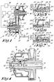
- a transmission unit for motor vehicles which comprises a continuously variable transmission 2, as well as means for changing the transmission ratio thereof.
- the continuously variable transmission 2 mainly consists of an ingoing shaft 3, an outgoing shaft 4, two pulleys 5-6 which are mounted on the shafts 3 and 4 respectively, and an endless transmission element 7, such as a belt.
- the pulleys 5 and 6 are composed of conical pulley halves 8-9 and 10-11, of which each time one pulley half 8, respectively 10, is axially immobile and of which the second pulley half 9, respectively 11, is hydraulically displaceable in axial direction.
- the means for changing the transmission ratio consist of cylinder-piston units 12 and 13 which cooperate with the displaceable pulley halves 9 and 11 respectively.
- the transmission ratio can be changed.
- the ingoing shaft 3 is driven by the motor 17 of the vehicle, by means of a coupling and reversing unit 18.
- the outgoing shaft 4 provides in the driving of the front and/of back wheels 19 over a transmission 20 and differential 21.
- This pressure compensation chamber 22 mainly consists of the prolongation of the cylinder 23 of the cylinder-piston unit 13 and a deflecting partition 24.
- the pressure compensation chamber 22 and the pressure chamber 15 are situated at opposite sides of the piston 25 and can be connected by means of a passage 26.
- the surplus hydraulic medium can leave the pressure compensation chamber 22 through a relatively wide opening 27.
- the passage 26 is situated at the location of the shaft, in this case the outgoing shaft 4, whereby this passage 26 extends through this shaft 4 from in front of to behind the piston 25 and, thereby, can realize a connection between the pressure chamber 15 and the pressure compensation chamber 22.
- the passage 26 is provided with a passage regulation 28 which provides for that the passage 26 is only opened as soon as a well-defined position between the pulley halves 10-11 is surpassed, more particularly a position whereby in the normal usage position higher rotational speeds will occur and a pressure compensation is desired.
- the passage regulation 28 preferably is integrated in the shaft and hub construction which is formed by the shaft 4 and the hub 29, in such a manner that the shifting of the hub 29 over the shaft 4 functions as a slide valve.
- the passage 26 to this end can be composed of a conduit system 30 through the hub 29, which, on one hand, connects to the pressure chamber 15 and/or with the pressure supply conduit 31 to this pressure chamber 15, and, on the other hand, gives out on the shaft 4, and a conduit system 32 cooperating therewith, extending through the shaft 4, which, on one hand, gives out under the hub 29 and, on the other hand, gives out in the pressure compensation chamber 22, whereby a connection between the two conduit systems 30-32 is made as soon as the hub 29 takes a well-defined axial position in respect to the shaft 4.
- the conduit system 30 is preferably formed by an axial recess 33, provided at the inside of the hub 29, of a well-defined length, which gives out in the passage 34 connecting the pressure supply conduit 31 and the pressure chamber 15.
- the conduit system 32 preferably consists of radial bores 35-36 which are situated at opposite sides of the piston 25 and are connected to each other by means of an axial channel 37.
- the deflecting partition 24 is constructed in such a manner that the free extremity 38 is situated beyond the piston 25, in such a manner that it is axially also situated further than the exit 39 of the passage 26, however, at least for the positions whereby a connection is established between the pressure chamber 15 and the pressure compensation chamber 22.
- the passage 26 constructively can be realized rather simple as then no special provisions have to be made in order to obtain that the hydraulic medium, emerging from the passage 26, gets between the piston 25 and the deflecting partition 24.
- the deflecting partition 24, at least for the position whereby the displaceable pulley half 11 is situated in the closest proximity to the axially fixed pulley half 10, and more particularly for all positions whereby no open connection by means of the passage 26 is established, is situated with its free extremity 38 in front of or at the height of the exit 39.
- the cylinder 23 becomes unnecessary long and the construction might gain unnecessary weight.
- a passage member 40 may be provided which, for example, consists of an element which is pressed or screwed into the bore 36 and which is provided with a restriction 41 which is chosen such that the optimum flow rate is obtained.
- the pressure supply conduit 31 is situated at the side of the movable pulley half 11, and the channel 37 extends radially alongside thereto.
- the pressure supply conduit 31 preferably is situated in the center of the shaft 4, and the channel 37 is situated at a distance outside therefrom.
- the restriction 41 preferably is situated between a radius R1 which is somewhat smaller than the radius R2 of the shaft 4, for example, is 70 % thereof, and the radius R3 of the circumference of the hub 29. Furthermore, the restriction 41 preferably is provided at the location of the aforementioned bore 35.
- FIG 4 a variant is represented whereby the pressure supply conduit 31 is situated at the side of the axially fixed pulley half 10.
- the pressure supply conduit 31 is situated at the side of the axially fixed pulley half 10.
- the channel 37 is situated in the turning center of the shaft 4, which results in a better counterbalance.
- restriction 41 may be realized at different locations.
- the passage member 40 with the restriction 41 is provided in the hub 29.
- passage regulation 28 it is, according to the invention, not excluded to make use of a permanent passage 26, for example, such as represented in figure 6.
- a pressure-sensitive passage-regulating element may be installed, for example, of the type such as described in BE 1.005.746 of applicant, either combined with a passage regulation 28 as mentioned heretofore or not.
- the exit 39 not necessarily has to be at the location of the shaft 4.
- a channel may be connected to the bore 36, as a result of which the exit 39 becomes situated at a larger radial distance, between the piston 25 and the deflecting partition 24.
- Such channel 42 may, for example, extend through the piston 25, such as represented in figure 7.
- the secondary pulley 6 revolves faster than the primary pulley 5. Consequently, the invention described heretofore will preferably be applied at least to the secondary pulley 6 and shall, in the case that a passage regulation 28 is applied, this latter be realized in such a manner that the passage 26 is closed as soon as the running radius of the transmission element 7 on the secondary pulley 6 surpasses a predetermined value.
- a passage regulation 28 is applied, this latter be realized in such a manner that the passage 26 is closed as soon as the running radius of the transmission element 7 on the secondary pulley 6 surpasses a predetermined value.
- both pulleys 5-6, or only the primary pulley 5 may be equipped with a pressure compensation system according to the invention.
Landscapes
- Engineering & Computer Science (AREA)
- General Engineering & Computer Science (AREA)
- Mechanical Engineering (AREA)
- Transmissions By Endless Flexible Members (AREA)
- Control Of Transmission Device (AREA)
Applications Claiming Priority (2)
| Application Number | Priority Date | Filing Date | Title |
|---|---|---|---|
| BE9600557A BE1010369A3 (nl) | 1996-06-18 | 1996-06-18 | Transmissie-eenheid voor motorvoertuigen. |
| BE9600557 | 1996-06-18 |
Publications (2)
| Publication Number | Publication Date |
|---|---|
| EP0814284A1 true EP0814284A1 (fr) | 1997-12-29 |
| EP0814284B1 EP0814284B1 (fr) | 2000-03-08 |
Family
ID=3889820
Family Applications (1)
| Application Number | Title | Priority Date | Filing Date |
|---|---|---|---|
| EP19970201729 Expired - Lifetime EP0814284B1 (fr) | 1996-06-18 | 1997-06-07 | Variateur continu de vitesse pour véhicule à moteur |
Country Status (4)
| Country | Link |
|---|---|
| EP (1) | EP0814284B1 (fr) |
| BE (1) | BE1010369A3 (fr) |
| DE (1) | DE69701368T2 (fr) |
| ES (1) | ES2147420T3 (fr) |
Citations (6)
| Publication number | Priority date | Publication date | Assignee | Title |
|---|---|---|---|---|
| US4143558A (en) | 1975-11-06 | 1979-03-13 | Van Doorne's Transmissie B.V. | Variable-V-belt transmission |
| GB2064686A (en) * | 1979-12-03 | 1981-06-17 | Aisin Warner | Belt type stepless variable-ratio gear |
| JPS58193962A (ja) * | 1982-05-10 | 1983-11-11 | Aisin Seiki Co Ltd | 無段変速機の回転補償装置 |
| EP0321921A1 (fr) * | 1987-12-23 | 1989-06-28 | Fuji Jukogyo Kabushiki Kaisha | Variateur continu de vitesse avec dispositif de poulie à diamètre variable |
| EP0520611A1 (fr) * | 1991-06-26 | 1992-12-30 | Borg-Warner Automotive Transmission And Engine Components Corporation | Deuxième poulie servo à double effet pour une transmission à variation continue |
| BE1005746A3 (nl) | 1992-03-13 | 1994-01-11 | Volvo Car Sint Truiden | Transmissie-eenheid voor motorvoertuigen. |
-
1996
- 1996-06-18 BE BE9600557A patent/BE1010369A3/nl not_active IP Right Cessation
-
1997
- 1997-06-07 DE DE1997601368 patent/DE69701368T2/de not_active Expired - Fee Related
- 1997-06-07 EP EP19970201729 patent/EP0814284B1/fr not_active Expired - Lifetime
- 1997-06-07 ES ES97201729T patent/ES2147420T3/es not_active Expired - Lifetime
Patent Citations (6)
| Publication number | Priority date | Publication date | Assignee | Title |
|---|---|---|---|---|
| US4143558A (en) | 1975-11-06 | 1979-03-13 | Van Doorne's Transmissie B.V. | Variable-V-belt transmission |
| GB2064686A (en) * | 1979-12-03 | 1981-06-17 | Aisin Warner | Belt type stepless variable-ratio gear |
| JPS58193962A (ja) * | 1982-05-10 | 1983-11-11 | Aisin Seiki Co Ltd | 無段変速機の回転補償装置 |
| EP0321921A1 (fr) * | 1987-12-23 | 1989-06-28 | Fuji Jukogyo Kabushiki Kaisha | Variateur continu de vitesse avec dispositif de poulie à diamètre variable |
| EP0520611A1 (fr) * | 1991-06-26 | 1992-12-30 | Borg-Warner Automotive Transmission And Engine Components Corporation | Deuxième poulie servo à double effet pour une transmission à variation continue |
| BE1005746A3 (nl) | 1992-03-13 | 1994-01-11 | Volvo Car Sint Truiden | Transmissie-eenheid voor motorvoertuigen. |
Non-Patent Citations (1)
| Title |
|---|
| PATENT ABSTRACTS OF JAPAN vol. 8, no. 37 (M - 277)<1474> 17 February 1984 (1984-02-17) * |
Also Published As
| Publication number | Publication date |
|---|---|
| DE69701368T2 (de) | 2000-08-24 |
| BE1010369A3 (nl) | 1998-07-07 |
| DE69701368D1 (de) | 2000-04-13 |
| EP0814284B1 (fr) | 2000-03-08 |
| ES2147420T3 (es) | 2000-09-01 |
Similar Documents
| Publication | Publication Date | Title |
|---|---|---|
| US5725447A (en) | Power train with infinitely variable ratio transmission | |
| US5711730A (en) | Torque monitoring apparatus | |
| CA1130112A (fr) | Transmission par poulie a largeur de gorge variable | |
| US4143558A (en) | Variable-V-belt transmission | |
| US5108348A (en) | Ratio control for a continuously variable transmission | |
| US4228691A (en) | Variable pulley transmission | |
| EP0194821B1 (fr) | Variateur continu de vitesse | |
| US5605513A (en) | Method for lubricating/cooling transmission in motor vehicle | |
| US5908367A (en) | Flow rate control valve and continuously variable automatic transmission provided with same | |
| KR20010015799A (ko) | 연속적 가변 원추형 풀리 또는 밸트 접촉 기어박스 | |
| US6361470B1 (en) | Adjustable pulley for fluid-operated transmissions | |
| US4790214A (en) | Revolution speed ratio control system for a continuously variable transmission | |
| US4512751A (en) | Method and system for controlling continuously variable v-belt transmission | |
| WO2008037665A1 (fr) | Transmission variable en continu avec un système de commande hydraulique, et procédé pour commander ladite transmission | |
| US4958495A (en) | Hydraulic differential cylinder | |
| EP0814284B1 (fr) | Variateur continu de vitesse pour véhicule à moteur | |
| US5334104A (en) | Transmission unit for motor vehicles | |
| JP2827727B2 (ja) | 無段変速機の油圧制御装置 | |
| DE3786445T2 (de) | Druckregelungsventil. | |
| US4653353A (en) | Spool-type control valve assembly with reduced spool stroke for hydraulic belt-and-pulley type continuously variable transmission | |
| US5095698A (en) | Hydrostatic transmission | |
| US4469333A (en) | Sealing device in a transmission with pressure-medium controlled, continuously variable gear ratio | |
| JP2699331B2 (ja) | 車両用ベルト式無段変速機の油圧制御装置 | |
| JP3158842B2 (ja) | 無段変速機のオイル通路構造 | |
| JPS61206862A (ja) | 無段可変伝動装置 |
Legal Events
| Date | Code | Title | Description |
|---|---|---|---|
| PUAI | Public reference made under article 153(3) epc to a published international application that has entered the european phase |
Free format text: ORIGINAL CODE: 0009012 |
|
| AK | Designated contracting states |
Kind code of ref document: A1 Designated state(s): BE CH DE ES FR GB IT LI LU NL |
|
| 17P | Request for examination filed |
Effective date: 19980217 |
|
| AKX | Designation fees paid |
Free format text: BE CH DE ES FR GB IT LI LU NL |
|
| RBV | Designated contracting states (corrected) |
Designated state(s): BE CH DE ES FR GB IT LI LU NL |
|
| 17Q | First examination report despatched |
Effective date: 19990408 |
|
| GRAG | Despatch of communication of intention to grant |
Free format text: ORIGINAL CODE: EPIDOS AGRA |
|
| RIC1 | Information provided on ipc code assigned before grant |
Free format text: 6F 16H 61/00 A, 6F 16H 55/52 B |
|
| GRAG | Despatch of communication of intention to grant |
Free format text: ORIGINAL CODE: EPIDOS AGRA |
|
| GRAH | Despatch of communication of intention to grant a patent |
Free format text: ORIGINAL CODE: EPIDOS IGRA |
|
| GRAH | Despatch of communication of intention to grant a patent |
Free format text: ORIGINAL CODE: EPIDOS IGRA |
|
| GRAA | (expected) grant |
Free format text: ORIGINAL CODE: 0009210 |
|
| AK | Designated contracting states |
Kind code of ref document: B1 Designated state(s): BE CH DE ES FR GB IT LI LU NL |
|
| REG | Reference to a national code |
Ref country code: CH Ref legal event code: EP |
|
| REF | Corresponds to: |
Ref document number: 69701368 Country of ref document: DE Date of ref document: 20000413 |
|
| REG | Reference to a national code |
Ref country code: CH Ref legal event code: NV Representative=s name: DIPL.-ING. ETH H. R. WERFFELI PATENTANWALT |
|
| ITF | It: translation for a ep patent filed | ||
| ET | Fr: translation filed | ||
| REG | Reference to a national code |
Ref country code: ES Ref legal event code: FG2A Ref document number: 2147420 Country of ref document: ES Kind code of ref document: T3 |
|
| PLBE | No opposition filed within time limit |
Free format text: ORIGINAL CODE: 0009261 |
|
| STAA | Information on the status of an ep patent application or granted ep patent |
Free format text: STATUS: NO OPPOSITION FILED WITHIN TIME LIMIT |
|
| 26N | No opposition filed | ||
| REG | Reference to a national code |
Ref country code: GB Ref legal event code: IF02 |
|
| PGFP | Annual fee paid to national office [announced via postgrant information from national office to epo] |
Ref country code: GB Payment date: 20040602 Year of fee payment: 8 |
|
| PGFP | Annual fee paid to national office [announced via postgrant information from national office to epo] |
Ref country code: NL Payment date: 20040603 Year of fee payment: 8 |
|
| PGFP | Annual fee paid to national office [announced via postgrant information from national office to epo] |
Ref country code: FR Payment date: 20040608 Year of fee payment: 8 |
|
| PGFP | Annual fee paid to national office [announced via postgrant information from national office to epo] |
Ref country code: LU Payment date: 20040616 Year of fee payment: 8 Ref country code: CH Payment date: 20040616 Year of fee payment: 8 |
|
| PGFP | Annual fee paid to national office [announced via postgrant information from national office to epo] |
Ref country code: DE Payment date: 20040617 Year of fee payment: 8 |
|
| PGFP | Annual fee paid to national office [announced via postgrant information from national office to epo] |
Ref country code: ES Payment date: 20040621 Year of fee payment: 8 |
|
| PGFP | Annual fee paid to national office [announced via postgrant information from national office to epo] |
Ref country code: BE Payment date: 20040813 Year of fee payment: 8 |
|
| PG25 | Lapsed in a contracting state [announced via postgrant information from national office to epo] |
Ref country code: LU Free format text: LAPSE BECAUSE OF NON-PAYMENT OF DUE FEES Effective date: 20050607 Ref country code: IT Free format text: LAPSE BECAUSE OF NON-PAYMENT OF DUE FEES;WARNING: LAPSES OF ITALIAN PATENTS WITH EFFECTIVE DATE BEFORE 2007 MAY HAVE OCCURRED AT ANY TIME BEFORE 2007. THE CORRECT EFFECTIVE DATE MAY BE DIFFERENT FROM THE ONE RECORDED. Effective date: 20050607 Ref country code: GB Free format text: LAPSE BECAUSE OF NON-PAYMENT OF DUE FEES Effective date: 20050607 |
|
| PG25 | Lapsed in a contracting state [announced via postgrant information from national office to epo] |
Ref country code: ES Free format text: LAPSE BECAUSE OF NON-PAYMENT OF DUE FEES Effective date: 20050608 |
|
| PG25 | Lapsed in a contracting state [announced via postgrant information from national office to epo] |
Ref country code: LI Free format text: LAPSE BECAUSE OF NON-PAYMENT OF DUE FEES Effective date: 20050630 Ref country code: CH Free format text: LAPSE BECAUSE OF NON-PAYMENT OF DUE FEES Effective date: 20050630 Ref country code: BE Free format text: LAPSE BECAUSE OF NON-PAYMENT OF DUE FEES Effective date: 20050630 |
|
| PG25 | Lapsed in a contracting state [announced via postgrant information from national office to epo] |
Ref country code: NL Free format text: LAPSE BECAUSE OF NON-PAYMENT OF DUE FEES Effective date: 20060101 |
|
| PG25 | Lapsed in a contracting state [announced via postgrant information from national office to epo] |
Ref country code: DE Free format text: LAPSE BECAUSE OF NON-PAYMENT OF DUE FEES Effective date: 20060103 |
|
| REG | Reference to a national code |
Ref country code: CH Ref legal event code: PL |
|
| PG25 | Lapsed in a contracting state [announced via postgrant information from national office to epo] |
Ref country code: FR Free format text: LAPSE BECAUSE OF NON-PAYMENT OF DUE FEES Effective date: 20060228 |
|
| GBPC | Gb: european patent ceased through non-payment of renewal fee |
Effective date: 20050607 |
|
| NLV4 | Nl: lapsed or anulled due to non-payment of the annual fee |
Effective date: 20060101 |
|
| REG | Reference to a national code |
Ref country code: FR Ref legal event code: ST Effective date: 20060228 |
|
| REG | Reference to a national code |
Ref country code: ES Ref legal event code: FD2A Effective date: 20050608 |
|
| BERE | Be: lapsed |
Owner name: *VCST N.V. Effective date: 20050630 |