EP0814295B1 - Raccord rapide pour tuyaux - Google Patents
Raccord rapide pour tuyaux Download PDFInfo
- Publication number
- EP0814295B1 EP0814295B1 EP97110048A EP97110048A EP0814295B1 EP 0814295 B1 EP0814295 B1 EP 0814295B1 EP 97110048 A EP97110048 A EP 97110048A EP 97110048 A EP97110048 A EP 97110048A EP 0814295 B1 EP0814295 B1 EP 0814295B1
- Authority
- EP
- European Patent Office
- Prior art keywords
- conduit
- stud
- wall
- port
- block
- Prior art date
- Legal status (The legal status is an assumption and is not a legal conclusion. Google has not performed a legal analysis and makes no representation as to the accuracy of the status listed.)
- Expired - Lifetime
Links
Images

Classifications
-
- F—MECHANICAL ENGINEERING; LIGHTING; HEATING; WEAPONS; BLASTING
- F16—ENGINEERING ELEMENTS AND UNITS; GENERAL MEASURES FOR PRODUCING AND MAINTAINING EFFECTIVE FUNCTIONING OF MACHINES OR INSTALLATIONS; THERMAL INSULATION IN GENERAL
- F16L—PIPES; JOINTS OR FITTINGS FOR PIPES; SUPPORTS FOR PIPES, CABLES OR PROTECTIVE TUBING; MEANS FOR THERMAL INSULATION IN GENERAL
- F16L41/00—Branching pipes; Joining pipes to walls
- F16L41/08—Joining pipes to walls or pipes, the joined pipe axis being perpendicular to the plane of a wall or to the axis of another pipe
- F16L41/086—Joining pipes to walls or pipes, the joined pipe axis being perpendicular to the plane of a wall or to the axis of another pipe fixed with screws
-
- B—PERFORMING OPERATIONS; TRANSPORTING
- B60—VEHICLES IN GENERAL
- B60H—ARRANGEMENTS OF HEATING, COOLING, VENTILATING OR OTHER AIR-TREATING DEVICES SPECIALLY ADAPTED FOR PASSENGER OR GOODS SPACES OF VEHICLES
- B60H1/00—Heating, cooling or ventilating devices
- B60H1/00507—Details, e.g. mounting arrangements, desaeration devices
- B60H1/00557—Details of ducts or cables
- B60H1/00571—Details of ducts or cables of liquid ducts, e.g. for coolant liquids or refrigerants
-
- Y—GENERAL TAGGING OF NEW TECHNOLOGICAL DEVELOPMENTS; GENERAL TAGGING OF CROSS-SECTIONAL TECHNOLOGIES SPANNING OVER SEVERAL SECTIONS OF THE IPC; TECHNICAL SUBJECTS COVERED BY FORMER USPC CROSS-REFERENCE ART COLLECTIONS [XRACs] AND DIGESTS
- Y10—TECHNICAL SUBJECTS COVERED BY FORMER USPC
- Y10S—TECHNICAL SUBJECTS COVERED BY FORMER USPC CROSS-REFERENCE ART COLLECTIONS [XRACs] AND DIGESTS
- Y10S285/00—Pipe joints or couplings
- Y10S285/906—Equivalents
-
- Y—GENERAL TAGGING OF NEW TECHNOLOGICAL DEVELOPMENTS; GENERAL TAGGING OF CROSS-SECTIONAL TECHNOLOGIES SPANNING OVER SEVERAL SECTIONS OF THE IPC; TECHNICAL SUBJECTS COVERED BY FORMER USPC CROSS-REFERENCE ART COLLECTIONS [XRACs] AND DIGESTS
- Y10—TECHNICAL SUBJECTS COVERED BY FORMER USPC
- Y10T—TECHNICAL SUBJECTS COVERED BY FORMER US CLASSIFICATION
- Y10T29/00—Metal working
- Y10T29/49—Method of mechanical manufacture
- Y10T29/49826—Assembling or joining
- Y10T29/49863—Assembling or joining with prestressing of part
- Y10T29/4987—Elastic joining of parts
- Y10T29/49872—Confining elastic part in socket
-
- Y—GENERAL TAGGING OF NEW TECHNOLOGICAL DEVELOPMENTS; GENERAL TAGGING OF CROSS-SECTIONAL TECHNOLOGIES SPANNING OVER SEVERAL SECTIONS OF THE IPC; TECHNICAL SUBJECTS COVERED BY FORMER USPC CROSS-REFERENCE ART COLLECTIONS [XRACs] AND DIGESTS
- Y10—TECHNICAL SUBJECTS COVERED BY FORMER USPC
- Y10T—TECHNICAL SUBJECTS COVERED BY FORMER US CLASSIFICATION
- Y10T29/00—Metal working
- Y10T29/49—Method of mechanical manufacture
- Y10T29/49826—Assembling or joining
- Y10T29/49863—Assembling or joining with prestressing of part
- Y10T29/49876—Assembling or joining with prestressing of part by snap fit
-
- Y—GENERAL TAGGING OF NEW TECHNOLOGICAL DEVELOPMENTS; GENERAL TAGGING OF CROSS-SECTIONAL TECHNOLOGIES SPANNING OVER SEVERAL SECTIONS OF THE IPC; TECHNICAL SUBJECTS COVERED BY FORMER USPC CROSS-REFERENCE ART COLLECTIONS [XRACs] AND DIGESTS
- Y10—TECHNICAL SUBJECTS COVERED BY FORMER USPC
- Y10T—TECHNICAL SUBJECTS COVERED BY FORMER US CLASSIFICATION
- Y10T29/00—Metal working
- Y10T29/49—Method of mechanical manufacture
- Y10T29/49826—Assembling or joining
- Y10T29/49947—Assembling or joining by applying separate fastener
- Y10T29/49948—Multipart cooperating fastener [e.g., bolt and nut]
- Y10T29/49952—At least one part is nonmetallic
Definitions
- the present invention relates to conduit attachments and particularly conduit employed for communicating flow of pressurized refrigerant and the connection of such conduits to a wall or block such as in a refrigerant expansion valve or receiver/drier header.
- the present invention relates to the fast or quick connection of refrigerant conduits to a wall or block and particularly relates to such quick connection in the assembly and installation of automotive passenger compartment air conditioning systems in high-volume mass production.
- connection of the type having a connector plate attached to the end of the refrigerant conduit to be connected; and, the connector plate is fastened to the block or wall having a fluid connecting port for connection to the conduit, the attachment being made typically by threaded fasteners such as a machine screw or bolt received through the plate.
- FIG. 5 The aforesaid known type of conduit connection employed for refrigerant conduits attached to a port in a block or wall B is shown in FIG. 5 where a plate I is attached to the conduit 2 and is sealed in a port 3 by means of a protrusion 4 on the plate having an annular seal ring 5 received in the port.
- the conduit 2 is attached to the plate by a crimped flange 6; and, a separate hole 7 is provided in the plate for attachment to the block by means of a suitable threaded fastener 9.
- US-A-5 354 103 which relates to a technique for connecting tubular fluid pressure conduits into spaced ports having internal seal rings in a common side of a valve or block.
- a plastic spring lock member which is retained by a cover bolted to the block comprises apertures coinciding with the ports.
- the convolution expands the aperture of the spring lock member, thus permitting the convolution to snap through and the conduit to be retained in the port with the periphery of the conduit end contacting the internal seal ring.
- EP-A-0 521 776 discloses a plate having two cut-outs that is rotated in order to secure two conduits within their respective ports. Each conduit comprising a convolution that is placed within an undercut formed at the top of each port.
- the present invention provides a quick or fast connection of a conduit to a port in a block or wall and is particularly suitable for quick connection of conduits to such a port for flow of pressurized refrigerant through the conduit to the port.
- the present invention has particular applicability to the assembly and installation of refrigerant conduit in automotive air conditioning systems where it is desired to provide a quick connect without the need for separate fasteners or tools of a conduit to a port in a block or wall of a system component in high-volume mass production.
- the present invention provides a conduit having an enlargement or protrusion on the conduit end to be connected to the port.
- An attachment plate has a cut-out therein with the conduit received in the cut-out and contacting the enlargement.
- the conduit is secured thereto by a pair of convolutions or rings formed on the conduit.
- a pre-assembled stud is releasably fastened to the block or wall adjacent the fluid port; and, a separate cut-out or aperture in the plate is received over the stud and snap-locked thereon with the enlarged end of the conduit being simultaneously inserted and sealed in the port.
- the snap-locking is preferably accomplished by a snap ring provided in the plate aperture which is snapped over an undercut or barb provided on the stud. If it is desired subsequently to remove the connection, the stud may be removed such as by unthreading from the block or wall and the plate and conduit removed.
- the present invention thus provides a unique and novel technique for assembling a fluid pressure conduit to a port in a block or wall with a quick connect or snap-lock attachment over a stud which makes the connection between the conduit and the fluid port and retains the conduit secured therein without separate tools or fasteners.
- the connection may thereafter be broken or disconnected by unthreading the stud.
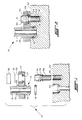
- the conduit connection of the present invention is indicated generally at 10 and includes a conduit or tube 12 having an enlarged end indicated generally at 14 and which has an annular groove 16 formed thereon into which is received an annular seal ring 18.
- An attachment plate 20 has a cut-out formed therein which may either be an aperture or an open slot into which the conduit 12 is received.
- annular ring 24 is received over the conduit 12 and secured thereto for retaining the conduit in the cut-out 22.
- ring 24 may be formed integrally in the tube wall as a convolution, as may the enlarged end 14.
- Attachment plate 20 has a second cut-out or aperture 26 with a reduced diameter portion 27 and formed therein spaced from the cut-out 22 with a resilient snap ring 28 received therein and retained by a collar or ring 30 pressed in the aperture 26.
- Ring 28 is shown in FIG. 2 as having a rectangular cross section, but a circular cross section ring may also be employed.
- a block or wall 32 such as the block of an expansion valve or header of a receiver/drier, has a fluid port 34 formed therein which is sized and configured to have received therein the enlarged end 14 of conduit 12 in a manner such that seal ring 18 is compressed in groove 16 and a fluid pressure tight seal is formed therebetween.
- a bore 36 is formed in block 32 spaced from port 34 by an amount to coincide with aperture 26.
- Bore 36 has a stud 38 releasably and preferably threadedly engaged therein; and, the portion of stud 38 extending externally of the bore 36 is provided with a taper 40 and an undercut or relief 39 is provided adjacent the largest diameter of the taper thereby forming an annular barb on the stud.
- stud 38 is provided pre-assembled to the block 32 and is thus in place at the time of the connection of conduit 12.
- FIG. 4(a) the conduit connection of the present invention is shown at the beginning of installation.
- FIGS. 4(a), (b) and (c) the invention is shown using an alternative configuration for the snap ring 28' having a circular transverse section.
- FIG. 4(a) the tapered portion 40 of the stud 38 is illustrated as inserted into the aperture 26 to a point where it initially contacts the snap ring 28'.
- the plate 22 has been moved downwardly an additional amount from the position shown in FIG. 4(a) until the taper 40 of the stud 38 has expanded the snap ring 28' to its greatest diameter and to a condition where it is at incipient snap-over of the taper 40.
- the plate 22 has been moved downwardly to contact the upper surface of block 32 and the tapered portion 40 of stud 38 has passed through the snap ring 28' which has now contracted or snapped into the undercut region 39 of the stud 38 such that ring 28' prevents removal of the plate by the engagement of the reduced diameter portion 27 of aperture 26 with the ring 28'.
- the stud 38 may be removed by insertion of a tool (not shown) such as an Allen wrench or hexagonal bit into the socket 41 through the plate aperture 26 and the stud unthreaded from block 32.
- a tool such as an Allen wrench or hexagonal bit
- an alternate embodiment of the invention is indicated generally at 50 as having the adaptor plate 122 formed with a conically tapered portion in the aperture 126 and an undercut 139 formed adjacent the smallest diameter of the tapered portion 140 thereby forming an internal annular barb.
- a stud 138 has the upper portion thereof formed with a straight cylindrical configuration; and, an annular groove 143 is formed thereon into which snap ring 28' is engaged and resiliently compressible therein such that the ring 28' may pass through the tapered portion 140 and expand into undercut an amount sufficient to retain the plate 122 on the stud 138.
- the present invention thus provides a novel and unique quick or fast connection for a conduit for communicating pressurized fluid to a port formed in a block or wall.
- a connection plate secured to the conduit is snap-locked over a tapered stud provided in releasable, preferably threaded engagement with the block or wall. Subsequent disconnection of the conduit is enabled by unthreading of the stud from the block or wall.
Landscapes
- Engineering & Computer Science (AREA)
- General Engineering & Computer Science (AREA)
- Mechanical Engineering (AREA)
- Physics & Mathematics (AREA)
- Thermal Sciences (AREA)
- Quick-Acting Or Multi-Walled Pipe Joints (AREA)
Claims (11)
- Un procédé pour assembler un conduit tubulaire (12) à une paroi ou à un bloc (32) de façon à y permettre l'écoulement d'un fluide sous pression comprenant les étapes consistant :(a) à former une protubérance ou partie élargie (14) sur une extrémité d'un conduit tubulaire (12) ;(b) à réaliser une plaque de montage (20; 122) et à y former une découpe (22) et à y former une ouverture (26 ; 126) espacée de ladite découpe (22) ;(c) à placer ledit conduit (12) dans ladite découpe (22) ;(d) à former un orifice (34) pour fluide sous pression dans ladite paroi (32) et à insérer ladite partie élargie (14) dans ledit orifice (34) et à établir un joint étanche entre eux ;(e) à fixer de manière amovible un goujon (38 ; 138) dans ladite paroi ou ledit bloc ; et(f) à préassembler ledit goujon (38 ; 138) avec ledit bloc ou ladite paroi (32) et à insérer ledit goujon préassemblé (38; 138) dans ladite ouverture (26 ; 126), déformant ainsi un organe élastiquement déformable (28 ; 28') disposé entre ledit goujon (38 ; 138) et ladite ouverture (26, 126) et retenant ladite plaque (20 ; 122) sur ledit bloc ou ladite paroi (32) et ledit conduit (12) dans ledit orifice (34).
- Le procédé défini dans la revendication 1, dans lequel un dégagement ou évidement (39 ; 139) est formé pour recevoir ledit organe élastiquement déformable qui y est inséré.
- Le procédé défini dans la revendication 1, dans lequel ladite étape consistant à fixer ledit goujon (38) de manière amovible consiste à visser ledit goujon (38 ; 138) dans ledit bloc (32) ou ladite paroi.
- Le procédé défini dans la revendication 1, dans lequel ladite étape consistant à établir un joint étanche entre ledit orifice et ladite partie élargie (14) comporte l'étape qui consiste à former une gorge annulaire dans ladite partie élargie (14) du conduit et à y disposer une bague élastique (18).
- Le procédé défini dans la revendication 1, comprenant, en outre, l'étape qui consiste à séparer ledit goujon (38 ; 138) dudit bloc (32) et à détacher ledit conduit (12) dudit orifice (34).
- Le procédé défini dans la revendication 1, dans lequel ladite étape consistant à former une partie élargie (14) comporte l'étape qui consiste à former au moins une circonvolution dans la paroi dudit conduit (12).
- Le procédé défini dans la revendication 1, comprenant, en outre, les étapes qui consistent à mettre ladite partie élargie (14) en contact avec ladite plaque (20) et à retirer ledit goujon (38 ; 138) pour détacher ledit conduit (12) dudit orifice (34).
- Le procédé défini dans l'une quelconque des revendications précédentes, dans lequel ladite étape d'insertion de ladite partie élargie (14) comporte l'étape qui consiste à disposer un joint d'étanchéité (18) entre ladite partie élargie (14) et ledit orifice (34).
- Le procédé défini dans l'une quelconque des revendications précédentes, dans lequel l'étape d'insertion dudit goujon (38) comporte l'étape qui consiste à utiliser un verrouillage par action brusque.
- Le procédé défini dans l'une quelconque des revendications précédentes, dans lequel ladite étape de placement dudit conduit (12) dans ladite découpe (22) comporte l'étape qui consiste à fixer ledit conduit à ladite plaque (20).
- Le procédé défini dans l'une quelconque des revendications précédentes, dans lequel ladite étape de placement dudit conduit (12) dans ladite découpe (22) comporte l'étape qui consiste à former une paire de circonvolutions dans la paroi dudit conduit et à fixer ledit conduit à ladite plaque (20).
Applications Claiming Priority (2)
| Application Number | Priority Date | Filing Date | Title |
|---|---|---|---|
| US668590 | 1996-06-19 | ||
| US08/668,590 US5727304A (en) | 1996-06-19 | 1996-06-19 | Conduit fast connection |
Publications (3)
| Publication Number | Publication Date |
|---|---|
| EP0814295A2 EP0814295A2 (fr) | 1997-12-29 |
| EP0814295A3 EP0814295A3 (fr) | 1998-06-10 |
| EP0814295B1 true EP0814295B1 (fr) | 2001-02-28 |
Family
ID=24682962
Family Applications (1)
| Application Number | Title | Priority Date | Filing Date |
|---|---|---|---|
| EP97110048A Expired - Lifetime EP0814295B1 (fr) | 1996-06-19 | 1997-06-19 | Raccord rapide pour tuyaux |
Country Status (4)
| Country | Link |
|---|---|
| US (1) | US5727304A (fr) |
| EP (1) | EP0814295B1 (fr) |
| CA (1) | CA2208816C (fr) |
| DE (1) | DE69704134T2 (fr) |
Families Citing this family (28)
| Publication number | Priority date | Publication date | Assignee | Title |
|---|---|---|---|---|
| US6260265B1 (en) * | 1998-04-27 | 2001-07-17 | Power Distribution Products | Circuit board stiffener |
| FR2783303B1 (fr) * | 1998-09-15 | 2000-12-01 | Valeo Climatisation | Dispositif de raccordement, notamment pour une installation de climatisation de vehicule automobile |
| US6312020B1 (en) * | 1999-08-10 | 2001-11-06 | Ti Group Automotive Systems Corp | Connector for connecting a hose to a fluid path within a bore |
| US6431614B1 (en) * | 1999-10-29 | 2002-08-13 | Automotive Fluid Systems, Inc. | Anti-cantilever fastener for a conduit connection |
| US6193283B1 (en) | 1999-10-29 | 2001-02-27 | Automotive Fluid Systems, Inc. | Conduit and block connection indicator device |
| DE29921168U1 (de) * | 1999-12-02 | 2001-04-05 | Ing. Walter Hengst GmbH & Co KG, 48147 Münster | Flüssigkeitsfilter mit demontierbarem, zentralen Bauteil, mit zusätzlichem Haltebauteil |
| DE10044765A1 (de) * | 2000-09-11 | 2002-05-08 | Eaton Fluid Power Gmbh | Leitungssteckverbindungseinrichtung |
| US6908117B1 (en) | 2000-10-06 | 2005-06-21 | Hutchinson Fts, Inc. | Block-conduit connection alignment device |
| DE10136339C1 (de) * | 2001-07-26 | 2003-02-27 | Eaton Fluid Power Gmbh | Steckverbindungseinrichtung, insbesondere für Fluidleitungen |
| DE60215484T2 (de) * | 2002-03-27 | 2007-04-19 | Ohtsuka Co., Ltd. | Verfahren zur herstellung einer flanschverbindung |
| US6676167B2 (en) * | 2002-05-20 | 2004-01-13 | Visteon Global Technologies, Inc. | Air conditioning block fitting with two surface sealing |
| DE10303350B3 (de) * | 2003-01-29 | 2004-08-12 | Daimlerchrysler Ag | Steckverbindung |
| DE50303104D1 (de) * | 2003-02-05 | 2006-06-01 | Contitech Kuehner Gmbh & Cie Kg | Verbindungsanordnung für Kältemittelleitungen |
| US20040207200A1 (en) * | 2003-04-15 | 2004-10-21 | Nikhil Baxi | Low profile connection detail |
| DE102005020259A1 (de) * | 2005-04-30 | 2006-11-09 | Contitech Kühner Gmbh & Cie. Kg | Verbindungsanordnung für Kältemittelleitungen |
| US7591486B2 (en) * | 2005-07-01 | 2009-09-22 | Chrysler Group Llc | Fluid connector |
| JP4926964B2 (ja) * | 2005-08-03 | 2012-05-09 | イーグル工業株式会社 | 配管継手 |
| US7621568B2 (en) * | 2006-04-25 | 2009-11-24 | Visteon Global Technologies, Inc. | Block fitting and seal structure |
| DE202006019525U1 (de) * | 2006-12-28 | 2008-05-08 | Voss Automotive Gmbh | Blockverbinder für Fluidleitungen |
| GB2449071A (en) * | 2007-05-05 | 2008-11-12 | Rolls Royce Plc | Fluid coupling |
| KR20090063992A (ko) * | 2007-12-14 | 2009-06-18 | 현대자동차주식회사 | 자동변속기용 오일쿨러 장착유닛 |
| US9261194B2 (en) * | 2010-03-01 | 2016-02-16 | Hanon Systems | Metal seal fitting constraints |
| US8468849B2 (en) * | 2010-03-05 | 2013-06-25 | Visteon Global Technologies, Inc. | Double metal seal fitting |
| CH705415A2 (de) * | 2011-08-16 | 2013-02-28 | Peter A Mueller | Fluidanschluss. |
| DE102016206459B3 (de) * | 2016-04-18 | 2017-10-05 | Continental Automotive Gmbh | Kombination, umfassend ein Gehäuse und einen Flansch, und Anordnung |
| CN110831828B (zh) * | 2018-06-13 | 2022-09-16 | 大陆-特韦斯股份有限公司 | 防旋转班卓琴形连接件和包含所述连接件的液压部件安装组件 |
| CN117189973A (zh) * | 2022-05-31 | 2023-12-08 | 芜湖美的智能厨电制造有限公司 | 一种燃气管连接结构 |
| US12485866B2 (en) * | 2023-02-17 | 2025-12-02 | Ford Global Technologies, Llc | Brake line with attachment assembly for easy installation |
Family Cites Families (12)
| Publication number | Priority date | Publication date | Assignee | Title |
|---|---|---|---|---|
| US2069377A (en) * | 1935-04-23 | 1937-02-02 | Meyer Coupling Company Inc | Coupling device |
| US2819099A (en) * | 1953-06-12 | 1958-01-07 | Westinghouse Air Brake Co | Flange union fitting with contractible lined wedge |
| US3031049A (en) * | 1958-03-31 | 1962-04-24 | A V R Achat Ventes Representat | Fastening device for metal constructions |
| US3291495A (en) * | 1964-07-07 | 1966-12-13 | Illinois Milling Inc | Self-aligning seal |
| CA1042035A (fr) * | 1976-04-15 | 1978-11-07 | Jackson A. Smith | Adaptateur etanche pour bride divisee |
| US4407531A (en) * | 1981-03-27 | 1983-10-04 | Rca Corporation | Externally adjustable seal and bearing structure |
| US4672732A (en) * | 1986-02-27 | 1987-06-16 | Rca Corporation | Method of fixedly attaching a component to a base member |
| US5093976A (en) * | 1990-08-13 | 1992-03-10 | General Motors Corporation | Method of mounting trim to a motor vehicle |
| JP2520895Y2 (ja) * | 1990-12-28 | 1996-12-18 | 曙ブレーキ工業株式会社 | ディスクブレーキの圧油導入部 |
| FR2678706B1 (fr) * | 1991-07-05 | 1993-11-05 | Peugeot Automobiles | Bride de raccordement de deux tuyaux a deux conduits, en particulier pour vehicule automobile. |
| US5163716A (en) * | 1991-10-25 | 1992-11-17 | General Motors Corporation | Condenser connector assembly for connecting refrigerant line |
| US5354103A (en) * | 1994-01-28 | 1994-10-11 | Eaton Corporation | Quick connect conduit coupling |
-
1996
- 1996-06-19 US US08/668,590 patent/US5727304A/en not_active Expired - Fee Related
-
1997
- 1997-06-18 CA CA002208816A patent/CA2208816C/fr not_active Expired - Fee Related
- 1997-06-19 EP EP97110048A patent/EP0814295B1/fr not_active Expired - Lifetime
- 1997-06-19 DE DE69704134T patent/DE69704134T2/de not_active Expired - Fee Related
Also Published As
| Publication number | Publication date |
|---|---|
| US5727304A (en) | 1998-03-17 |
| EP0814295A2 (fr) | 1997-12-29 |
| EP0814295A3 (fr) | 1998-06-10 |
| CA2208816C (fr) | 2004-01-13 |
| CA2208816A1 (fr) | 1997-12-19 |
| DE69704134D1 (de) | 2001-04-05 |
| DE69704134T2 (de) | 2001-09-13 |
Similar Documents
| Publication | Publication Date | Title |
|---|---|---|
| US5727304A (en) | Conduit fast connection | |
| EP0665400B1 (fr) | Raccord rapide | |
| US5860681A (en) | Connecting block with inserts | |
| US5467611A (en) | Two plate TXV block connector for automotive A/C system with common bolts and independently attachable sides | |
| US7017239B2 (en) | Component connection system | |
| CN111120745B (zh) | 具有带凸片的固持器的联接器 | |
| US6682100B2 (en) | Connection block with clip | |
| EP0756119B1 (fr) | Raccords pour équipements hydrauliques | |
| US7891380B2 (en) | Protective cap for quick connector | |
| US20050258646A1 (en) | Quick connector | |
| US7988201B2 (en) | Fluid coupling assembly having a rotatable coupling | |
| EP0795101A1 (fr) | Raccord rapide a verrouillage franc | |
| AU660129B1 (en) | Quick connect swivel coupling | |
| US6193283B1 (en) | Conduit and block connection indicator device | |
| US5308125A (en) | Sealed connector for automotive A/C system | |
| EP4232737B1 (fr) | Ensemble de connexion de fluide | |
| EP0830538A1 (fr) | Raccord rapide haute pression pour utilisation dans des systemes de freinage pour automobiles | |
| US6328073B1 (en) | Fluid-tight conduit connection and method of making same | |
| EP0868629A4 (fr) | Dispositif de raccord instantane de conduites hydrauliques haute densite pour systemes de freinage anti-blocage et/ou de commande de traction | |
| AU678981B2 (en) | Tubular assembly and method of making same | |
| US20040094960A1 (en) | Clamp assembly | |
| US20090160182A1 (en) | Retainer Assembly for Conduit Connection | |
| US5992894A (en) | Plural conduit quick-connect | |
| US20040051314A1 (en) | Fluid quick connector for threaded fluid components | |
| US20040093726A1 (en) | Plug-in hose connector device |
Legal Events
| Date | Code | Title | Description |
|---|---|---|---|
| PUAI | Public reference made under article 153(3) epc to a published international application that has entered the european phase |
Free format text: ORIGINAL CODE: 0009012 |
|
| AK | Designated contracting states |
Kind code of ref document: A2 Designated state(s): DE FR GB IT |
|
| RIN1 | Information on inventor provided before grant (corrected) |
Inventor name: EYBERGEN, WILLIAM NICHOLAS |
|
| PUAL | Search report despatched |
Free format text: ORIGINAL CODE: 0009013 |
|
| AK | Designated contracting states |
Kind code of ref document: A3 Designated state(s): AT BE CH DE DK ES FI FR GB GR IE IT LI LU MC NL PT SE |
|
| 17P | Request for examination filed |
Effective date: 19981207 |
|
| AKX | Designation fees paid |
Free format text: DE FR GB IT |
|
| RBV | Designated contracting states (corrected) |
Designated state(s): DE FR GB IT |
|
| 17Q | First examination report despatched |
Effective date: 19990330 |
|
| GRAG | Despatch of communication of intention to grant |
Free format text: ORIGINAL CODE: EPIDOS AGRA |
|
| GRAG | Despatch of communication of intention to grant |
Free format text: ORIGINAL CODE: EPIDOS AGRA |
|
| GRAH | Despatch of communication of intention to grant a patent |
Free format text: ORIGINAL CODE: EPIDOS IGRA |
|
| GRAH | Despatch of communication of intention to grant a patent |
Free format text: ORIGINAL CODE: EPIDOS IGRA |
|
| GRAA | (expected) grant |
Free format text: ORIGINAL CODE: 0009210 |
|
| AK | Designated contracting states |
Kind code of ref document: B1 Designated state(s): DE FR GB IT |
|
| ITF | It: translation for a ep patent filed | ||
| REF | Corresponds to: |
Ref document number: 69704134 Country of ref document: DE Date of ref document: 20010405 |
|
| ET | Fr: translation filed | ||
| REG | Reference to a national code |
Ref country code: GB Ref legal event code: IF02 |
|
| PLBE | No opposition filed within time limit |
Free format text: ORIGINAL CODE: 0009261 |
|
| STAA | Information on the status of an ep patent application or granted ep patent |
Free format text: STATUS: NO OPPOSITION FILED WITHIN TIME LIMIT |
|
| 26N | No opposition filed | ||
| PGFP | Annual fee paid to national office [announced via postgrant information from national office to epo] |
Ref country code: GB Payment date: 20030501 Year of fee payment: 7 |
|
| PGFP | Annual fee paid to national office [announced via postgrant information from national office to epo] |
Ref country code: FR Payment date: 20030602 Year of fee payment: 7 |
|
| PGFP | Annual fee paid to national office [announced via postgrant information from national office to epo] |
Ref country code: DE Payment date: 20030630 Year of fee payment: 7 |
|
| PG25 | Lapsed in a contracting state [announced via postgrant information from national office to epo] |
Ref country code: GB Free format text: LAPSE BECAUSE OF NON-PAYMENT OF DUE FEES Effective date: 20040619 |
|
| PG25 | Lapsed in a contracting state [announced via postgrant information from national office to epo] |
Ref country code: DE Free format text: LAPSE BECAUSE OF NON-PAYMENT OF DUE FEES Effective date: 20050101 |
|
| GBPC | Gb: european patent ceased through non-payment of renewal fee |
Effective date: 20040619 |
|
| PG25 | Lapsed in a contracting state [announced via postgrant information from national office to epo] |
Ref country code: FR Free format text: LAPSE BECAUSE OF NON-PAYMENT OF DUE FEES Effective date: 20050228 |
|
| REG | Reference to a national code |
Ref country code: FR Ref legal event code: ST |
|
| PG25 | Lapsed in a contracting state [announced via postgrant information from national office to epo] |
Ref country code: IT Free format text: LAPSE BECAUSE OF NON-PAYMENT OF DUE FEES Effective date: 20050619 |