EP0814323A1 - Kabelstutzvorrichtung - Google Patents
Kabelstutzvorrichtung Download PDFInfo
- Publication number
- EP0814323A1 EP0814323A1 EP96113780A EP96113780A EP0814323A1 EP 0814323 A1 EP0814323 A1 EP 0814323A1 EP 96113780 A EP96113780 A EP 96113780A EP 96113780 A EP96113780 A EP 96113780A EP 0814323 A1 EP0814323 A1 EP 0814323A1
- Authority
- EP
- European Patent Office
- Prior art keywords
- support strip
- cable
- length
- tool holder
- support
- Prior art date
- Legal status (The legal status is an assumption and is not a legal conclusion. Google has not performed a legal analysis and makes no representation as to the accuracy of the status listed.)
- Granted
Links
- 230000007423 decrease Effects 0.000 claims abstract description 5
- 238000004891 communication Methods 0.000 claims description 2
- 239000000463 material Substances 0.000 description 12
- 230000007246 mechanism Effects 0.000 description 5
- 239000004020 conductor Substances 0.000 description 2
- 239000002184 metal Substances 0.000 description 2
- 238000007665 sagging Methods 0.000 description 2
- 238000010276 construction Methods 0.000 description 1
- 230000001419 dependent effect Effects 0.000 description 1
- 239000012530 fluid Substances 0.000 description 1
- 230000004886 head movement Effects 0.000 description 1
- 230000002452 interceptive effect Effects 0.000 description 1
- 238000000034 method Methods 0.000 description 1
Images

Classifications
-
- G—PHYSICS
- G01—MEASURING; TESTING
- G01D—MEASURING NOT SPECIALLY ADAPTED FOR A SPECIFIC VARIABLE; ARRANGEMENTS FOR MEASURING TWO OR MORE VARIABLES NOT COVERED IN A SINGLE OTHER SUBCLASS; TARIFF METERING APPARATUS; MEASURING OR TESTING NOT OTHERWISE PROVIDED FOR
- G01D15/00—Component parts of recorders for measuring arrangements not specially adapted for a specific variable
- G01D15/24—Drives for recording elements and surfaces not covered by G01D5/00
-
- H—ELECTRICITY
- H02—GENERATION; CONVERSION OR DISTRIBUTION OF ELECTRIC POWER
- H02G—INSTALLATION OF ELECTRIC CABLES OR LINES, OR OF COMBINED OPTICAL AND ELECTRIC CABLES OR LINES
- H02G11/00—Arrangements of electric cables or lines between relatively-movable parts
- H02G11/006—Arrangements of electric cables or lines between relatively-movable parts using extensible carrier for the cable, e.g. self-coiling spring
Definitions
- the present invention relates generally to controlling the operation of a plotter or similar x-y positioning mechanism; and deals more particularly with a device for supporting a ribbon cable attached to a movable tool head for such mechanisms.
- the present invention has particular utility in connection with the operation of plotters for use with sheet type work materials and is described herein as applied to such use.
- Plotters particularly drum plotters, require the simultaneous motion of several components in order to properly function.
- one of these moving components often referred to as a tool head holds and manipulates the tool or implement used to perform a work operation on the work material processed by the plotter.
- a tool head holds and manipulates the tool or implement used to perform a work operation on the work material processed by the plotter.
- Several different implements can be held by the tool head. For example, a pen can be used to draw an outline on the work material, a print head can be used to print a graphic on the work material, or a knife can be employed to cut a shaped piece from the work material.
- the tool head is often mounted on an elongated support located above and extending across the width of the work material and can move back and forth across the support's length, thereby allowing work operations to be performed across the width of the work material. Additionally, the tool head is capable of moving vertically relative to the support between a lowered working position and an upper non-working position.
- a suitable supply conduit is needed which is often in the form of a ribbon cable consisting of a number of flexible individual electrical conductors, and/or pressure fluid conductors, joined together to form a flat tape.
- the ribbon cable is vertically looped into a loop configuration wherein an upper length of the cable is positioned above a substantially parallel lower length with the upper and lower lengths being joined by a 180° bend in the cable.
- the upper and lower lengths of the looped cable increase or decrease in length dependent upon the direction of tool head movement.
- the ribbon cable In known plotters, the ribbon cable is contained within a channel.
- the channel is intended to protect and guide the cable during plotter operation, but when contained in such channel, the cable has been known to contact the upper surface of the channel and bind against it. When this happens, the same problem as previously described may occur. In the past, this binding problem has been dealt with by reducing the friction between the ribbon cable and the channel.
- TeflonTM a trademark of Dupont
- low friction tapes have been installed on the upper surface of the channel, but with mixed results.
- a more specific object of the present invention to provide a means for retaining a ribbon cable support such that the ribbon cable, the support mechanism, and the tool holder all move in concert.
- a still further object of the present invention is to retain the ribbon support mechanism in such a manner as to eliminate the likelihood of fatigue failure.
- the present invention resides in a ribbon cable support device for a plotter comprising a tool head support carried by the frame of the plotter and having a predetermined length.
- a tool head carrying a tool for work on the work material is slidably mounted to the tool head support.
- a drive means associated with the tool head drives the tool head back and forth along the length of the support in response to commands issued from a controller.
- a ribbon cable is attached at one end to the tool holder, and at its other end is in communication with the controller to enable the tool holder to receive commands from the controller.
- the cable has sufficient slack between the tool holder and the controller to allow the end of the cable attached to the tool head to move with the tool head.
- the ribbon cable is supported by a support device including, an elongated trough member mounted to the plotter frame for guiding the cable as its one end moves with the tool head.
- the trough member has a rear wall and opposed upper and lower walls defining a semi-enclosed interior channel containing the ribbon cable.
- the supporting device for the cable is a flexible support strip attached at one end to the lower wall of the trough member by a first clamping means and attached at its other end a second clamping means to the tool holder. This method of attachment causes the cable support strip to assume a vertically looped shape having an upper and lowers connected to one another by a 180° bend.
- the end of the cable support strip attached to the tool head moves with the tool head thereby causing one of the upper or lower support strip lengths to increase while the other decreases.
- the upper length of the ribbon cable is supported by the upper support strip length thereby preventing the ribbon cable from sagging and interfering with the travel of the tool head during operation of the plotter.
- the present invention further resides in the first clamping means comprising a clamping bar having a first and second end, and an upper and lower surface.
- the lower surface has a step in it such that the second end of the lower surface is upwardly offset from the first end of the lower surface.
- the clamping bar is attached at the first end of the lower surface to the trough lower wall.
- the clamping bar also has a threaded hole extending through the second end.
- One end of the cable support strip is positioned under the second end of the clamping bar lower surface.
- the step creates a gap between the clamping bar lower surface and the cable support strip.
- a portion of the ribbon cable is positioned between the cable support strip and the trough lower wall.
- a fastener is threaded into the threaded hole and brought into pressing engagement with the cable support strip thereby clamping the cable support strip and the ribbon cable at a single point between the fastener and the trough member lower wall.
- the cable support strip has a transverse width having an arcuate contour.
- a second clamp is provided to clamp the cable support strip to the tool head.
- the second clamp has an upper clamp member with a convex portion, and a lower clamp member having a concave portion.
- the concave and convex portions having substantially the same arcuate contour as the transverse width of the ribbon cable.
- An end of the ribbon cable support strip and a portion of the ribbon cable are interposed between the concave and convex portions.
- the convex portion seats within the concave portion.
- the upper and lower clamp members are connected by fasteners, such that the cable support strip and the ribbon cable are clamped between the upper and lower clamp members without significantly deforming the arcuate shape of the transverse width of the cable support strip.
- a plotter having a cable support device there shown and generally designated as 10, comprises a frame 12, a tool head support 14 is mounted to the frame 12.
- a tool head 16 is slidably mounted to the frame 12 such that it can traverse the width of the work material 18 being processed.
- a drive means 20 is provided to drive the tool head 16 along the tool head support 14 in response to commands issued from a controller 22.
- a ribbon cable 24 is connected at one end to the controller 22 and at a second end, to the tool head 16.
- the ribbon cable 24 provides the means by which the data necessary to control the work material processing operation is transferred from the controller 22 to the tool head 16. As such, the ribbon cable 24 must move at the end connected to the tool head 16, with the tool head 16. Therefore, ribbon cable 24 must have sufficient slack to allow the tool head to traverse the length of the tool head support 14.
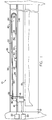
- a cable support device there shown and generally designated as 26 comprises, an elongated trough member 38 mounted to the frame 12 having a semi-enclosed interior area 40.
- the semi-enclosed interior area 40 is defined by upper wall 42, opposed lower wall 46, and rear wall 44.
- An elongated cable support strip 28 having ends 34, 36 is positioned in said semi-enclosed interior area.
- the elongated cable support strip 28 is made of a suitable material such as, for example, a thin metal strip.
- the thin metal strip is of the type used in conventional tape measures and has an arcuate contour 48, best seen in Fig. 3.
- the cable support strip 28 is attached at one end 34 to the trough lower wall 46 by clamp 30.
- the cable support strip is attached at a second end 36 to the tool head 16 by clamp 32.
- one end of the cable support strip 28 moves with the tool head 16 as it traverses the length of the tool head support 14. Therefore, to facilitate the tool head's motion, sufficient slack must be provided in the cable support strip 28 as well.
- the cable support strip 28 is positioned in the semi- enclosed interior area 40 in the form of vertical loop having an upper support strip length 52 positioned above a lower support strip length 54 with the upper support strip length 52 and the lower support strip length 54 connected to one another by a 180° bend 56 in the support strip.
- an upper support strip length 52 positioned above a lower support strip length 54 with the upper support strip length 52 and the lower support strip length 54 connected to one another by a 180° bend 56 in the support strip.
- the first clamp comprises a clamping bar 58 having first end 60, second end 62, an upper surface 64 and a lower surface 66.
- the lower surface 66 having a step 68 such that the lower surface second end 70 is upwardly offset from the lower surface first end 72.
- the clamping bar 58 is attached at the lower surface first end 72 to the trough lower wall 46.
- a gap 73 is created between the trough lower wall 46 and the lower surface second end 70.
- the clamping bar has a threaded hole 74 extending through the second end 62.
- the cable support strip 28 is positioned in the gap 73 under the lower surface second end 70.
- a portion of the ribbon cable 24 is positioned in the gap 73 between the ribbon cable support strip 28 and the trough lower wall 46.
- a screw 76 is threadedly engaged in the threaded hole 74 and is in pressing engagement with the cable support strip 28 thereby clamping both the cable support strip 28 and the ribbon cable 24 at a single point between the screw and the trough member lower wall. While a screw is shown and described herein, it should be understood that in its broader aspects, the present invention is not limited in this regard and that other forms of fasteners may be substituted for the ones illustrated.
- the second clamp 32 is attached to the tool head 16.
- the second clamp 32 has an upper clamp member 77 and a lower clamp member 80.
- the upper clamp member has a convex portion 78 with substantially the same arcuate contour as the cable support strip 28.
- the lower clamp member 80 has a concave portion 82, also having substantially the same arcuate contour as the transverse width of the cable support strip 28.
- the upper and lower clamp members 77 and 80 are connected by screws 84, 84 such that the cable support strip 28 and the ribbon cable 24 are clamped between the upper and lower clamp members 77 and 80 without significantly deforming the arcuate contour of the transverse width of the cable support strip 28. While screws are shown and described herein, it should be understood that in its broader aspects, the present invention is not limited in this regard and that other forms of fasteners may be substituted for the ones illustrated.
Landscapes
- Physics & Mathematics (AREA)
- General Physics & Mathematics (AREA)
- Accessory Devices And Overall Control Thereof (AREA)
Applications Claiming Priority (2)
| Application Number | Priority Date | Filing Date | Title |
|---|---|---|---|
| US08/666,248 US5768789A (en) | 1996-06-20 | 1996-06-20 | Cable support device |
| US666248 | 1996-06-20 |
Publications (2)
| Publication Number | Publication Date |
|---|---|
| EP0814323A1 true EP0814323A1 (de) | 1997-12-29 |
| EP0814323B1 EP0814323B1 (de) | 1999-10-06 |
Family
ID=24673404
Family Applications (1)
| Application Number | Title | Priority Date | Filing Date |
|---|---|---|---|
| EP96113780A Expired - Lifetime EP0814323B1 (de) | 1996-06-20 | 1996-08-28 | Plotter mit Flachbandleitung |
Country Status (4)
| Country | Link |
|---|---|
| US (1) | US5768789A (de) |
| EP (1) | EP0814323B1 (de) |
| JP (1) | JP3009867B2 (de) |
| DE (1) | DE69604571T2 (de) |
Families Citing this family (2)
| Publication number | Priority date | Publication date | Assignee | Title |
|---|---|---|---|---|
| GB9618158D0 (en) * | 1996-08-30 | 1996-10-09 | Sgs Thomson Microelectronics | Improvements in or relating to an ATM switch |
| JP6008396B2 (ja) * | 2012-10-29 | 2016-10-19 | スターテクノ株式会社 | 板材切断装置 |
Citations (2)
| Publication number | Priority date | Publication date | Assignee | Title |
|---|---|---|---|---|
| DE1675330A1 (de) * | 1968-02-05 | 1971-12-30 | Ernst Klein | Kabelfuehrungsrohr als Energieleitungstraeger zwischen einem beweglichen Verbraucher und einem ortsfesten Anschluss |
| DE3843665A1 (de) * | 1987-12-25 | 1989-07-06 | Juki Kk | Mechanismus zum halten eines langen, biegsamen elements |
Family Cites Families (4)
| Publication number | Priority date | Publication date | Assignee | Title |
|---|---|---|---|---|
| US3568321A (en) * | 1968-09-06 | 1971-03-09 | Electronic Associates | Low cost plotter |
| US4709483A (en) * | 1984-03-14 | 1987-12-01 | Wing Aero | Glass cutting device |
| US5005296A (en) * | 1989-09-15 | 1991-04-09 | Gerber Garment Technology, Inc. | Plotter and ink pressurizing pump |
| JPH07328882A (ja) * | 1994-06-08 | 1995-12-19 | Mitsuba Electric Mfg Co Ltd | X−y移動機構 |
-
1996
- 1996-06-20 US US08/666,248 patent/US5768789A/en not_active Expired - Fee Related
- 1996-08-28 EP EP96113780A patent/EP0814323B1/de not_active Expired - Lifetime
- 1996-08-28 DE DE69604571T patent/DE69604571T2/de not_active Expired - Fee Related
-
1997
- 1997-06-20 JP JP9164139A patent/JP3009867B2/ja not_active Expired - Fee Related
Patent Citations (2)
| Publication number | Priority date | Publication date | Assignee | Title |
|---|---|---|---|---|
| DE1675330A1 (de) * | 1968-02-05 | 1971-12-30 | Ernst Klein | Kabelfuehrungsrohr als Energieleitungstraeger zwischen einem beweglichen Verbraucher und einem ortsfesten Anschluss |
| DE3843665A1 (de) * | 1987-12-25 | 1989-07-06 | Juki Kk | Mechanismus zum halten eines langen, biegsamen elements |
Also Published As
| Publication number | Publication date |
|---|---|
| DE69604571T2 (de) | 2000-05-18 |
| JP3009867B2 (ja) | 2000-02-14 |
| JPH1071798A (ja) | 1998-03-17 |
| US5768789A (en) | 1998-06-23 |
| DE69604571D1 (de) | 1999-11-11 |
| EP0814323B1 (de) | 1999-10-06 |
Similar Documents
| Publication | Publication Date | Title |
|---|---|---|
| EP3680074A1 (de) | Roboterhand, robotervorrichtung und verfahren zur herstellung einer elektronischen vorrichtung | |
| KR19990067359A (ko) | 절연재 스트리핑 장치 | |
| US5505398A (en) | Device for supplying and exchanging a plurality of cables | |
| US3699630A (en) | System for ordered dispensing of wire and the like | |
| CN1123130A (zh) | 剪切刀具 | |
| DE3346583C2 (de) | Vorrichtung zum Arbeiten auf bahnförmigem Material | |
| US5768789A (en) | Cable support device | |
| CA2774428A1 (en) | Pulling head assembly workstation | |
| US4704775A (en) | Turn gate for use with a robotic wire harness assembly system | |
| US3804130A (en) | Form board for receiving and removably retaining strand material | |
| JP7422358B2 (ja) | テープ切断装置 | |
| EP0666172B1 (de) | Datenaufzeichner für ein Bündel elektrischer Drähte | |
| US5957165A (en) | Apparatus for winding and tightening a band clip around a wiring harness | |
| US3890865A (en) | System for dispensing and cutting strand material | |
| US5442848A (en) | Wire positioning and cut-off tool | |
| JP2959617B2 (ja) | 直線移動機構のケーブルガイド | |
| EP3806608B1 (de) | Bandzuführer | |
| JP4425039B2 (ja) | テ−ピング部品供給装置及び部品実装装置 | |
| US3844462A (en) | Dispensing head for strand material | |
| CN213652880U (zh) | 剪线机构及具有其的缝纫机 | |
| GB2091438A (en) | Tape splicing | |
| WO2015098522A1 (ja) | 端子送り装置 | |
| US4949658A (en) | Tape feeding device in a tape winding stitching machine | |
| KR19980063283A (ko) | 테이프 부착장치 | |
| US5622329A (en) | Terminal band feeding device having efficient partitioning tape disposal which limits tension in the terminal band |
Legal Events
| Date | Code | Title | Description |
|---|---|---|---|
| PUAI | Public reference made under article 153(3) epc to a published international application that has entered the european phase |
Free format text: ORIGINAL CODE: 0009012 |
|
| 17P | Request for examination filed |
Effective date: 19960828 |
|
| AK | Designated contracting states |
Kind code of ref document: A1 Designated state(s): BE DE FR GB |
|
| AX | Request for extension of the european patent |
Free format text: AL;LT;LV;SI |
|
| DAX | Request for extension of the european patent (deleted) | ||
| 17Q | First examination report despatched |
Effective date: 19970910 |
|
| GRAG | Despatch of communication of intention to grant |
Free format text: ORIGINAL CODE: EPIDOS AGRA |
|
| GRAG | Despatch of communication of intention to grant |
Free format text: ORIGINAL CODE: EPIDOS AGRA |
|
| GRAG | Despatch of communication of intention to grant |
Free format text: ORIGINAL CODE: EPIDOS AGRA |
|
| GRAH | Despatch of communication of intention to grant a patent |
Free format text: ORIGINAL CODE: EPIDOS IGRA |
|
| GRAH | Despatch of communication of intention to grant a patent |
Free format text: ORIGINAL CODE: EPIDOS IGRA |
|
| GRAA | (expected) grant |
Free format text: ORIGINAL CODE: 0009210 |
|
| AK | Designated contracting states |
Kind code of ref document: B1 Designated state(s): BE DE FR GB |
|
| REF | Corresponds to: |
Ref document number: 69604571 Country of ref document: DE Date of ref document: 19991111 |
|
| ET | Fr: translation filed | ||
| PLBE | No opposition filed within time limit |
Free format text: ORIGINAL CODE: 0009261 |
|
| STAA | Information on the status of an ep patent application or granted ep patent |
Free format text: STATUS: NO OPPOSITION FILED WITHIN TIME LIMIT |
|
| 26N | No opposition filed | ||
| REG | Reference to a national code |
Ref country code: GB Ref legal event code: IF02 |
|
| PGFP | Annual fee paid to national office [announced via postgrant information from national office to epo] |
Ref country code: GB Payment date: 20020730 Year of fee payment: 7 |
|
| PGFP | Annual fee paid to national office [announced via postgrant information from national office to epo] |
Ref country code: BE Payment date: 20020801 Year of fee payment: 7 |
|
| PGFP | Annual fee paid to national office [announced via postgrant information from national office to epo] |
Ref country code: DE Payment date: 20020809 Year of fee payment: 7 |
|
| PGFP | Annual fee paid to national office [announced via postgrant information from national office to epo] |
Ref country code: FR Payment date: 20020812 Year of fee payment: 7 |
|
| PG25 | Lapsed in a contracting state [announced via postgrant information from national office to epo] |
Ref country code: GB Free format text: LAPSE BECAUSE OF NON-PAYMENT OF DUE FEES Effective date: 20030828 |
|
| PG25 | Lapsed in a contracting state [announced via postgrant information from national office to epo] |
Ref country code: BE Free format text: LAPSE BECAUSE OF NON-PAYMENT OF DUE FEES Effective date: 20030831 |
|
| BERE | Be: lapsed |
Owner name: *GERBER SCIENTIFIC PRODUCTS INC. Effective date: 20030831 |
|
| PG25 | Lapsed in a contracting state [announced via postgrant information from national office to epo] |
Ref country code: DE Free format text: LAPSE BECAUSE OF NON-PAYMENT OF DUE FEES Effective date: 20040302 |
|
| GBPC | Gb: european patent ceased through non-payment of renewal fee | ||
| PG25 | Lapsed in a contracting state [announced via postgrant information from national office to epo] |
Ref country code: FR Free format text: LAPSE BECAUSE OF NON-PAYMENT OF DUE FEES Effective date: 20040430 |
|
| REG | Reference to a national code |
Ref country code: FR Ref legal event code: ST |