EP0814342A2 - Detektionsgerät für magnetische Substanze in minimaler Menge in untersuchten langen Gegenständen - Google Patents
Detektionsgerät für magnetische Substanze in minimaler Menge in untersuchten langen Gegenständen Download PDFInfo
- Publication number
- EP0814342A2 EP0814342A2 EP97401424A EP97401424A EP0814342A2 EP 0814342 A2 EP0814342 A2 EP 0814342A2 EP 97401424 A EP97401424 A EP 97401424A EP 97401424 A EP97401424 A EP 97401424A EP 0814342 A2 EP0814342 A2 EP 0814342A2
- Authority
- EP
- European Patent Office
- Prior art keywords
- inspected
- magnetic
- magnetic sensor
- magnetic field
- detecting equipment
- Prior art date
- Legal status (The legal status is an assumption and is not a legal conclusion. Google has not performed a legal analysis and makes no representation as to the accuracy of the status listed.)
- Granted
Links
- 239000000126 substance Substances 0.000 title claims abstract description 21
- 241000238366 Cephalopoda Species 0.000 claims abstract description 42
- 230000004907 flux Effects 0.000 claims description 17
- 239000000463 material Substances 0.000 claims description 11
- 239000010409 thin film Substances 0.000 claims description 10
- 230000035945 sensitivity Effects 0.000 abstract description 9
- 239000010419 fine particle Substances 0.000 abstract description 2
- IJGRMHOSHXDMSA-UHFFFAOYSA-N Atomic nitrogen Chemical compound N#N IJGRMHOSHXDMSA-UHFFFAOYSA-N 0.000 description 8
- XEEYBQQBJWHFJM-UHFFFAOYSA-N Iron Chemical compound [Fe] XEEYBQQBJWHFJM-UHFFFAOYSA-N 0.000 description 8
- 238000010276 construction Methods 0.000 description 8
- 239000010949 copper Substances 0.000 description 7
- 238000001514 detection method Methods 0.000 description 6
- 238000009413 insulation Methods 0.000 description 6
- 239000004677 Nylon Substances 0.000 description 4
- 239000007788 liquid Substances 0.000 description 4
- 238000000034 method Methods 0.000 description 4
- 229910052757 nitrogen Inorganic materials 0.000 description 4
- 229920001778 nylon Polymers 0.000 description 4
- 239000002245 particle Substances 0.000 description 4
- 229920000728 polyester Polymers 0.000 description 4
- 239000000758 substrate Substances 0.000 description 4
- 230000015572 biosynthetic process Effects 0.000 description 3
- 229910000889 permalloy Inorganic materials 0.000 description 3
- RYGMFSIKBFXOCR-UHFFFAOYSA-N Copper Chemical compound [Cu] RYGMFSIKBFXOCR-UHFFFAOYSA-N 0.000 description 2
- 208000004350 Strabismus Diseases 0.000 description 2
- 239000002826 coolant Substances 0.000 description 2
- 230000007613 environmental effect Effects 0.000 description 2
- 238000009432 framing Methods 0.000 description 2
- 238000007654 immersion Methods 0.000 description 2
- 229910052742 iron Inorganic materials 0.000 description 2
- 238000002955 isolation Methods 0.000 description 2
- 238000004519 manufacturing process Methods 0.000 description 2
- 238000005259 measurement Methods 0.000 description 2
- 238000004804 winding Methods 0.000 description 2
- 229910002370 SrTiO3 Inorganic materials 0.000 description 1
- 230000008901 benefit Effects 0.000 description 1
- 230000008859 change Effects 0.000 description 1
- 239000011248 coating agent Substances 0.000 description 1
- 238000000576 coating method Methods 0.000 description 1
- 239000004020 conductor Substances 0.000 description 1
- 238000001816 cooling Methods 0.000 description 1
- 229910052802 copper Inorganic materials 0.000 description 1
- 238000000151 deposition Methods 0.000 description 1
- 230000000694 effects Effects 0.000 description 1
- 230000005674 electromagnetic induction Effects 0.000 description 1
- 230000008030 elimination Effects 0.000 description 1
- 238000003379 elimination reaction Methods 0.000 description 1
- 230000005415 magnetization Effects 0.000 description 1
- 230000008569 process Effects 0.000 description 1
- 239000006104 solid solution Substances 0.000 description 1
- 239000002887 superconductor Substances 0.000 description 1
Images

Classifications
-
- G—PHYSICS
- G01—MEASURING; TESTING
- G01R—MEASURING ELECTRIC VARIABLES; MEASURING MAGNETIC VARIABLES
- G01R33/00—Arrangements or instruments for measuring magnetic variables
- G01R33/02—Measuring direction or magnitude of magnetic fields or magnetic flux
- G01R33/035—Measuring direction or magnitude of magnetic fields or magnetic flux using superconductive devices
- G01R33/0354—SQUIDS
-
- G—PHYSICS
- G01—MEASURING; TESTING
- G01R—MEASURING ELECTRIC VARIABLES; MEASURING MAGNETIC VARIABLES
- G01R33/00—Arrangements or instruments for measuring magnetic variables
- G01R33/12—Measuring magnetic properties of articles or specimens of solids or fluids
Definitions
- the present invention relates to a detecting equipment of magnetic minute substance. More specifically, the detecting equipment of the present invention can detect continually in high sensitivity entity of fine particle without destroying an object to be inspected having shape of a wire or a lod.
- a foreign matter contained in a long material is possible cause of serious trouble even if the foreign matter is very small.
- Cu is to be a wire material as an electric conductor. At some time, it is thinned to less than 100 ⁇ m in diameter. However, Cu runs out on elongated process, when a foreign matter of less than 10 ⁇ m is contained in the Cu material. For other example, when a foreign matter of less than 10 ⁇ m exists in its isolation coating, proof pressure of a cable line conveying power in high voltage of 500 kV extremely deteriorates.
- This equipment detects a drift of a magnetic field including an object to be inspected caused of existence of a foreign matter.
- This equipment comprises a SQUID(Superconducting QUantum Interference Device) as a magnetic sensor having very high sensitivity. Accordingly, output signal of the SQUID is affected by a drift of the environmental magnetic field. Then, the circumference of the SQUID and the object to be inspected is surrounded with a magnetic shield container and detection of magnetic substance is done inside of the magnetic shield container.
- a magnetic shield container is made of a permalloy for example.
- an object to be inspected is a very long object like a wire
- the object to be inspected cannot be accommodated in a magnetic shield container.
- the detection is enforced while carrying in and out of the object to be inspected .
- object to be inspected is charge from one end of the magnetic shield container and carried out from the other end of the magnetic shield container simultaneously. Accordingly, a pair of opening needs to be made for the magnetic shield container. The object to be inspected is carried in and out through the openings.
- a magnetic shield container having special shape is used for inspecting a long object to be inspected and immersion of outside magnetic field is prevented by the shape of the container.
- a purpose of the present invention is to provide a detecting equipment having high detectivity and easy to use.
- the detecting equipment of the present invention comprises a magnetic field generation means and a magnetic sensor.
- the magnetic field generation means generates a magnetic field and an object to be inspected runs inside of the magnetic field along its overall length direction . Then the object to be inspected is magnetized.
- the magnetic sensor comprises a SQUID as a part of a magnetic sensor.
- Magnetic sensor is arranged in neighborhood of traveling path of the object to be inspected and more later than the magnetic field generation means. When magnetic substance is contained in the object to be inspected, magnetic field changes. The magnetic sensor detects the change of the magnetic field by the SQUID.
- the magnetic field generation means generates a magnetic field that is right angle to the traveling direction of the object to be inspected. Accordingly, the object to be inspected is magnetized in right angle to traveling direction. On the other hand, sensitivity of the magnetic sensor is highest in a specific direction.
- the direction that detectivity becomes highest is the direction that is right angle to formation surface of the SQUID.
- magnetic sensor comprises a SQUID and a flux transformer
- the direction is the direction that is right angle to the plane including the pickup coil of the flux transformer.
- the object to be inspected is magnetized before inspected by the magnetic sensor. Accordingly, a magnetic minute substance in a object to be inspected is magnetized in specified direction too. As a result, requirement to the magnetic shield container is moderated.
- a typical application of the detecting equipment of the present invention is check in manufacturing process of wire-rod material. In this field, the following fact is understood that most of the foreign matter in an object is fine iron particle.
- detecting equipment of the present invention at first, an object to be inspected runs inside of a magnetic field generated by the magnetic field generation means and next passes neighborhood of the magnetic sensor.
- a magnetic substance contained in the object to be inspected is magnetized by the magnetic field corresponding to each peculiar characteristic magnetic susceptibility.
- the magnetic field occurs a draft.
- the magnetic sensor detects a drift of the magnetic field. This is the principle of operation of the equipment of the present invention.
- the equipment of the present invention can detect extremely magnetic minute substance in high sensitivity.
- detection by SQUID is carried out in the magnetic shield container.
- Magnetic shield container defined a range covered from intercepting of outer magnetic field. The inner magnetic field is not disturbed by drift of the environment magnetic field.
- the magnetic shield container can be made of Permalloy for example.
- an opening for object to be inspected to pass is established with the magnetic shield container. Furthermore, when the long material is running in succession while inspected, inside diameter of the openings must be larger than the diameter of the object to be inspected. However, when inside diameter of the openings are so large, the outside magnetic field invades into the container through the openings. This is never desirable of course.
- the equipment of the present invention comprises a characteristic structure.
- an object to be inspected is magnetized in peculiar direction before the detecting by the magnetic sensor. Namely, magnetization is done in the magnetic field that is right angle to traveling direction of the object to be inspected. Accordingly, the magnetic sensor detects a drift of the magnetic field that is right angle to the traveling direction of the object to be inspected.
- a magnetic field invaded from the openings are the magnetic field that is parallel to the traveling direction of the object to be inspected. Accordingly, affect of outside magnetic field can be eliminated effectively by a magnetic shield container of simple configuration.
- the equipment of the present invention comprises several magnetic sensors.
- Each magnetic sensor is located each arranged location so that spacing from object to be inspected to each magnetic sensor is different mutually.
- Each magnetic sensor exhibit an unique output.
- Each output of the magnetic sensor is correspond to constant magnetic field and to spacing between the object to be inspected and each magnetic sensor. Accordingly, the true drift can be detected from difference between outputs of the magnetic sensors. Thus the affect of the outside magnetic field can be eliminated.
- a filter is inserted between the signal processing circuit and the output device. The filter lets pass only signal with specified frequency bandwidth.
- the SQUID as a magnetic sensor can be made of an oxide superconducting thin film. Because oxide superconducting thin film has a high superconducting critical temperature, it becomes a superconductor by cooling off with a liquid nitrogen. Liquid nitrogen is inexpensive and feeding of liquid nitrogen is stable. Accordingly, running cost of the magnetic sensor with a SQUID made of a superconducting thin film becomes low and manipulation of SQUID in operation is easy.
- the present invention realizes the following benefit.
- This equipment can detect extremely minute magnetic substance of minute dozens of ⁇ m dimension from an object to be inspected running in succession. Accordingly, gross quantity check in manufacturing process of long material can be enforced.
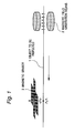
- Figure 1 is a figure of squint to show basic framing of the detecting equipment of the present invention.
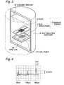
- Figure 2 is a part dap figure showing concrete construction of the detecting equipment of the present invention.
- Figure 3 is a part dap figure showing construction of usable magnetic sensor in the detecting equipment of the present invention.
- Figure 4 is a graph which resultant inspected using the detecting equipment shown in figure 2.
- Object to be inspected 1 is long material and travels along a constant path.
- the detecting equipment possesses a magnetic field generation means 2 and a magnetic sensor 3 arranged along object to be inspected 1.
- the magnetic field generation means 2 is generated the constant magnetic field which is right angle to the traveling direction of the object to be inspected 1.
- the object to be inspected 1 passes the inside of the magnetic field.
- the magnetic substance is magnetized according to its magnetic susceptibility while passing inside of the magnetic field.
- the object to be inspected 1 passes near to the magnetic sensor 3 comprising a SQUID.
- SQUID is formed on a plane which is right angle to the magnetic field.
- the SQUID When no magnetic substance is contained in the object to be inspected 1, the SQUID outputs constant signal corresponding to magnetic susceptibility of the object to be inspected 1.
- the magnetic field is peculiar changed by the magnetized substance and the output voltage of the SQUID changes.
- SQUID is been very sensitive to detect a drift of a magnetic field. Accordingly, magnetic minute substance can be detected.
- Figure 2 is a figure of squint to show one of a concrete framing of the detecting equipment of the present invention. On the figure 1, equal reference number was added to each element that is a common element in the figure 1.
- This detecting equipment comprises a magnetic field generation means 2, a magnetic sensor 3 and a magnetic shield container 4.
- the magnetic field generation means 2 comprises a pair of permanent magnets 21 and a yoke 22.
- the yoke 22 is put together permanent magnet 21 magnetically. The magnetic field toward one permanent magnet from another permanent magnet is generated.
- the magnetic sensor consists of a heat insulation container 34 and a SQUID that is arranged on the base of the heat insulation container horizontally.
- the heat insulation container 34 is met with a cooling medium.
- the SQUID is placed parallel to the traveling direction of the object to be inspected.
- the SQUID is arranged in right angle to the magnetic field generated by the magnetic field generation means, because the magnetic flux running through the SQUID becomes maximum.
- the SQUID functions as a magnetic sensor which has high sensitivity.
- the magnetic shield container 4 wraps up magnetic sensor 3 and a part of the object to be inspected that is traveling near by the magnetic sensor 3.
- the magnetic shield container 4 eliminates jamming by the environmental magnetic field to the magnetic sensor 3.
- the output signal of the magnetic sensor 3 is communicated to a signal processing equipment 5 that is based on a FLL(flux locked loop) circuit. Furthermore, a pen recorder 6 as a recording device is mounted to the signal processing equipment 5.
- One of concrete construction of the magnetic sensor can be use as the magnetic sensor 3 is shown in the figure 3.
- a SQUID without other attached device functions as a magnetic sensor.
- sensitivity of the SQUID as a magnetic sensor can be improved by jointly using with a flux transformer.
- the magnetic sensor 3 shown in the figure 3 comprises a SQUID 32 and a flux transformer 31.
- the SQUID 32 and the flux transformer 31 are each formed of a superconducting thin films on a substrates.
- a pickup coil 31A and an input coil 31B are connected each other.
- the pickup coil 31 A has a little winding numbers.
- the input coil 31 B has much winding numbers.
- Center of the input coil 31 B and center of the SQUID 32 accord with each other.
- the flux transformer 31 and SQUID 32 is taken into the heat insulation container 34.
- the heat insulation container 34 is met with a cooling medium 33 for example liquid nitrogen.
- SQUID 32 and flux transformer 31 are drawn separately. However, actually, the SQUID and the flux transformer are cohered to each other, while the superconducting thin film which forms the SQUID 32 is on lower surface of substrate. At the same time, it is preferred to insert an isolation layer between the SQUID 32 and the flux transformer 31 not to make a short-circuit.
- the input coil 31B and SQUID 32 is exaggerated in figure 3. But, their abbreviations are almost same dimension.
- length of the input coil 31 B on the bank is around 1/8 of overall length of the pickup coil 31 A on the bank. In figure 3, delineation is omitted about individual electric wiring.
- Magnetic sensor may be exchange to a gradiometer.
- So called gradiometer comprises a pair of electric coil which has opposite direction each other. Variation of magnetic field changing in the whole like an environment magnetic field is denied. Accordingly, there is some case that the magnetic shield container can be omitted.
- the SQUID and the flux transformer made of Y 1 Ba 2 Cu 3 O 7-x thin film deposited on SrTiO 3 substrate and patterned.
- the weak link department of SQUID made pattern breadth of thin film narrow.
- difference in grade that has bearing height of 1600 ⁇ was formed on the substrate before depositing thin film.
- Artificial grain boundary in the thin film is formed at a place of the difference in grade. The artificial grain boundary contributed to formation of a weak link, too.
- the magnetic field generation means was made with permanent magnets and arranged so that the object to be inspected passed in the magnetic field inside of approximately 0.1 tesla. Magnetic field generated was right angle to the traveling direction of the object to be inspected.
- the input coil of flux transformer arranged on the plane that was right angle to the magnetic flux generated.
- the input coil was arranged 15 mm apart from the pass of the object to be inspected. It is prefer to sensitivity of the magnetic sensor that the spacing between the object to be inspected and the magnetic. But, actually, by die thickness of the insulation container 34 , the spacing was forced to be 15 mm.
- Magnetic shield container which is formed a pair of openings to pass the object to be inspected was made of permalloy. The openings have diameter of 20 mm and are simple bore with no additional thing.
- Polyester line having a diameter of 0.5 mm and was prepared. It was confirmed beforehand that the polyester line contains no foreign matter. At the same time, iron powder which has a diameter of 60 ⁇ m, 100 ⁇ m or 180 ⁇ m was prepared. The polyester line was sticked the iron powder, and became an object to be inspected. The polyester line was inspected by the equipment while letting run by 10 m per second.
- the output of the signal processing equipment 5 was introduced into the pen recorder 6 through a filter.
- the filter was a lowpass filter having cut-off frequency of 10 Hz.
- the pen recorder 6 recorded measurement resultant which is described in figure 4.
- nylon line having a diameter of 0.5 mm was prepared. It was confirmed beforehand that the Nylon line itself includes no magnetic substance. Iron powder having a particle size of 500 ⁇ m was sticked to the nylon line.
- the nylon line was inspected by the detecting equipment mentioned above. At the same time, the same sample was inspected by the equipment of the present invention. As a result, a sensitivity of the present invention was high approximately 3 times to the equipment for comparing. In other words, the variation of output signal of the magnetic sensor was 3 times as much.
- the detecting equipment of this embodiment is different from the equipment of the first embodiment in period to have two magnetic sensors.
- each magnetic sensor has the same construction as the magnetic sensor shown in figure 3, too.
- the first magnetic sensor is arranged on the same location as the first embodiment. Namely, the first magnetic sensor is located the position that was 15 mm away from the object to be inspected. On the contrary, the second magnetic sensor is located 100 mm more distant from the object to be inspected than the first magnetic sensor. And the second magnetic sensor is arranged parallel to the first magnetic sensor.
- Output of the first magnetic sensor and output of the second magnetic sensor are each output through FLL circuits.
- the signal processing circuit comprises an operational amplifier receiving outputs of two FLL circuit at its input end.
- the operational amplifier outputs difference between the outputs of the two FLL circuit.
- the output signal of the operational amplifier is handled with signal processing circuit of the first embodiment in the same way as an output of a magnetic sensor. Such construction can let reduce affect of the earth magnetic field and background magnetic field. There is some case that the use of the magnetic shield container can be omitted.
- a signal corresponding to existence of a foreign matter is provided from the output of the first magnetic sensor.
- the reason is because the intensity of a magnetic field is in inverse proportion to 3 power of distance and because the first magnetic sensor is located near by the object to be inspected.
- the detectivity of the first magnetic sensor is approximately 450 times of the detectivity of the second magnetic sensor.
- the spacing between the first magnetic sensor and the second magnetic sensor is not limited to 100 mm. Larger distance is preferred so long as other conditions allow, because the signal strength can be lifted.
- the output voltage of one magnetic sensor is more than 2 times of the output voltage of the other magnetic sensor.
- the spacing between the first magnetic sensor and the object to be inspected is 15 mm
- the spacing of the second magnetic sensor and the object to be inspected meeting above-mentioned condition is 19 mm.. This value can be obtained from the expression 1.
- a copper wire having a diameter of 2.8 mm was prepared as an object to be inspected.
- Noise having random frequency was output from magnetic sensor at first. This noise was generated correspond to the traveling speed of the object to be inspected and effective detection could not completed.
- a possible cause is because a magnetic substance exists continually in the object to be inspected and the magnetic sensor detected it. It is thought that the magnetic substance exists in copper as solid solution.
- a band pass filter was inserted at the output of the signal processing circuit 5.
- the pass band of the filter was fitted to the peak frequency of noise correspond to the traveling speed of the wire.
- Condition of the measurement including the characteristic of the filter is shown in the following table.
- Table Object to be inspected Cu line Speed of the Cu line 40 m/minute Cut-off frequency of the band pass filter 20 Hz and 1 Hz Attenuation slope of the filter 42dB / oct.
Landscapes
- Physics & Mathematics (AREA)
- Condensed Matter Physics & Semiconductors (AREA)
- General Physics & Mathematics (AREA)
- Investigating Or Analyzing Materials By The Use Of Magnetic Means (AREA)
- Measuring Magnetic Variables (AREA)
- Geophysics And Detection Of Objects (AREA)
Applications Claiming Priority (2)
| Application Number | Priority Date | Filing Date | Title |
|---|---|---|---|
| JP181171/96 | 1996-06-21 | ||
| JP8181171A JPH1010091A (ja) | 1996-06-21 | 1996-06-21 | 磁性体微粉の検出装置 |
Publications (3)
| Publication Number | Publication Date |
|---|---|
| EP0814342A2 true EP0814342A2 (de) | 1997-12-29 |
| EP0814342A3 EP0814342A3 (de) | 1998-08-05 |
| EP0814342B1 EP0814342B1 (de) | 2007-11-14 |
Family
ID=16096134
Family Applications (1)
| Application Number | Title | Priority Date | Filing Date |
|---|---|---|---|
| EP97401424A Expired - Lifetime EP0814342B1 (de) | 1996-06-21 | 1997-06-19 | Detektionsgerät für magnetische Substanze in minimaler Menge in untersuchten langen Gegenständen |
Country Status (6)
| Country | Link |
|---|---|
| US (1) | US6157190A (de) |
| EP (1) | EP0814342B1 (de) |
| JP (1) | JPH1010091A (de) |
| KR (1) | KR980003630A (de) |
| CA (1) | CA2208383C (de) |
| DE (1) | DE69738282T2 (de) |
Families Citing this family (15)
| Publication number | Priority date | Publication date | Assignee | Title |
|---|---|---|---|---|
| DE19746000C2 (de) * | 1997-10-20 | 2002-05-16 | Forschungszentrum Juelich Gmbh | Verfahren zur Ermittlung von Defekten in Werkstücken sowie Magnetfeldmeßgerät zur Durchführung dieses Verfahrens |
| US6538569B1 (en) * | 1998-10-30 | 2003-03-25 | The Goodyear Tire & Rubber Company | Container with sensor |
| JP4171139B2 (ja) * | 1999-07-21 | 2008-10-22 | 住友電気工業株式会社 | 磁性体標識による免疫検査方法とその装置 |
| JP2004177131A (ja) * | 2002-11-22 | 2004-06-24 | National Institute For Materials Science | 非接触型荷物検知装置 |
| KR100451754B1 (ko) * | 2003-02-12 | 2004-10-08 | 엘지전자 주식회사 | 탭핑 모드를 이용한 자기장 분포 측정 장치 |
| JP4684695B2 (ja) * | 2004-03-23 | 2011-05-18 | 住友軽金属工業株式会社 | 非磁性金属管の表面欠陥検出装置 |
| US20100277164A1 (en) * | 2006-09-01 | 2010-11-04 | Commonwealth Scientific And Industrial Research Organisation | Method and apparatus for signal recovery |
| JP5041400B2 (ja) * | 2006-11-24 | 2012-10-03 | 国立大学法人大阪大学 | 異物の検出方法及び異物の検出装置 |
| JP2011237181A (ja) * | 2010-05-06 | 2011-11-24 | Toyohashi Univ Of Technology | 高性能磁気シールドと超高感度磁気センサを備えた微細金属検出装置 |
| EP2439560B1 (de) | 2010-10-07 | 2013-05-29 | Mettler-Toledo Safeline Limited | Verfahren für den Betrieb eines Metalldetektionssystems und Metalldetektionssystem |
| EP2439559B1 (de) | 2010-10-07 | 2013-05-29 | Mettler-Toledo Safeline Limited | Verfahren für den Betrieb eines Metalldetektionssystems und Metalldetektionssystem |
| US8587301B2 (en) | 2010-10-07 | 2013-11-19 | Mettler-Toledo Safeline Limited | Method for operating a metal detection system and metal detection system |
| US8717012B2 (en) * | 2011-04-28 | 2014-05-06 | The United States of America as respresented by the United States National Aeronautics and Space Administration | Eddy current probe for surface and sub-surface inspection |
| US9018935B2 (en) | 2011-09-19 | 2015-04-28 | Mettler-Toledo Safeline Limited | Method for operating a metal detection apparatus and apparatus |
| JP6993171B2 (ja) * | 2017-10-27 | 2022-01-13 | 協立電機株式会社 | 異物検出装置 |
Family Cites Families (6)
| Publication number | Priority date | Publication date | Assignee | Title |
|---|---|---|---|---|
| US3854085A (en) * | 1973-06-07 | 1974-12-10 | Magnetics Analysis Corp | Multi-probe flux leakage testing apparatus producing bipolar signals from the largest simultaneously occurring signals of each polarity |
| DE2431505C2 (de) * | 1974-07-01 | 1975-11-27 | Siemens Ag, 1000 Berlin Und 8000 Muenchen | Verfahren und Vorrichtung zur kontinuierlichen, kontaktlosen Prüfung eines langgestreckten, wenigstens teilweise aus Supraleitermaterial bestehenden Leiters |
| US3975934A (en) * | 1975-03-20 | 1976-08-24 | David Babai | Key-operated door locking device |
| US4734643A (en) * | 1985-08-05 | 1988-03-29 | Electrocom Automation, Inc. | Method and apparatus for detecting the presence of magnetic ink within a package by magnetizing and selectively remagnitizing the ferro-magnetic materials in the package |
| US5589772A (en) * | 1993-07-12 | 1996-12-31 | Sumitomo Electric Industries, Ltd. | Non-destructive eddy current sensor having a squid magnetic sensor and selectively positionable magnets |
| US5729135A (en) * | 1993-07-12 | 1998-03-17 | Sumitomo Electric Industries, Ltd. | Non-destructive testing equipment employing SQUID-type magnetic sensor in magnetic shield container |
-
1996
- 1996-06-21 JP JP8181171A patent/JPH1010091A/ja active Pending
-
1997
- 1997-06-19 EP EP97401424A patent/EP0814342B1/de not_active Expired - Lifetime
- 1997-06-19 DE DE69738282T patent/DE69738282T2/de not_active Expired - Fee Related
- 1997-06-20 CA CA002208383A patent/CA2208383C/en not_active Expired - Fee Related
- 1997-06-21 KR KR1019970026795A patent/KR980003630A/ko not_active Ceased
- 1997-06-23 US US08/880,554 patent/US6157190A/en not_active Expired - Fee Related
Also Published As
| Publication number | Publication date |
|---|---|
| EP0814342A3 (de) | 1998-08-05 |
| CA2208383A1 (en) | 1997-12-21 |
| US6157190A (en) | 2000-12-05 |
| CA2208383C (en) | 2002-02-19 |
| DE69738282T2 (de) | 2008-09-18 |
| KR980003630A (ko) | 1998-03-30 |
| JPH1010091A (ja) | 1998-01-16 |
| DE69738282D1 (de) | 2007-12-27 |
| EP0814342B1 (de) | 2007-11-14 |
Similar Documents
| Publication | Publication Date | Title |
|---|---|---|
| EP0814342B1 (de) | Detektionsgerät für magnetische Substanze in minimaler Menge in untersuchten langen Gegenständen | |
| Lee et al. | Magnetic gradiometer based on a high-transition temperature superconducting quantum interference device for improved sensitivity of a biosensor | |
| CA1222023A (en) | Miniature squid susceptometer | |
| EP1950578B1 (de) | Supraleitendes Quanteninterferometersystem (SQUID) zum Messen der magnetischen Suszeptibilität von Materialien | |
| EP0775917B1 (de) | Squidmagnetometer und zerstörungsfreies Prüfgerät | |
| US5004724A (en) | Superconductive quantum interference device for the non-destructive evaluation of metals | |
| JP2001515585A (ja) | 分析物の最高感度磁気検出装置 | |
| US6084399A (en) | Method and apparatus for determining concentration of magnetic substances in a non-magnetic substance using a SQUID | |
| US20060082368A1 (en) | Q-damping of a high temperature superconductor self-resonant coil in a nuclear quadrupole resonance detection system | |
| EP3496167B1 (de) | Strommessvorrichtung für geladenen teilchenstrahl | |
| Tanaka et al. | Development of Metallic Contaminant Detection System Using Eight-Channel High-$ T_ {c} $ SQUIDs | |
| US11255929B2 (en) | Electronic device for sensing magnetic fields | |
| Tanaka et al. | Development of metallic contaminant inspection system using high-Tc rf-SQUID for Li-ion battery liquid components | |
| Enpuku et al. | Biological immunoassay with high T c superconducting quantum interference device (SQUID) magnetometer | |
| Nagaishi et al. | NDT of high speed fine particles by high Tc SQUID | |
| Tanaka et al. | Contaminant detection system using high tc squid for inspection of lithium ion battery cathode sheet | |
| Tanaka et al. | Development of Metallic Contaminant Detection System Using High-Tc RF SQUIDs for Li-ion Battery Slurry | |
| ITOZAKI et al. | Detection of Fine lron Particles in High Speed Scrolled Wire by High-T c SQUID | |
| Seidel et al. | Improvement of spatial and field resolution in NDE systems using superconducting sensors | |
| Tanaka et al. | Metallic contaminant detection system using multi-channel superconducting quantum interference device (SQUID) | |
| Kawano et al. | Development of non-destructive evaluation system using an HTS-SQUID gradiometer for magnetized materials | |
| Schultze et al. | HTS SQUID gradiometer for application without shielding | |
| Ramos et al. | YBa2Cu3O7-dc SQUID array for multichannel magnetometry and multichannel flip-chip current sensors | |
| Takemoto et al. | Hts rf-squid microscope for metallic contaminant detection | |
| Faley et al. | A high temperature superconductor dc SQUID planar gradiometer measurement system for routine inspections |
Legal Events
| Date | Code | Title | Description |
|---|---|---|---|
| PUAI | Public reference made under article 153(3) epc to a published international application that has entered the european phase |
Free format text: ORIGINAL CODE: 0009012 |
|
| AK | Designated contracting states |
Kind code of ref document: A2 Designated state(s): DE FR GB IT NL |
|
| PUAL | Search report despatched |
Free format text: ORIGINAL CODE: 0009013 |
|
| AK | Designated contracting states |
Kind code of ref document: A3 Designated state(s): AT BE CH DE DK ES FI FR GB GR IE IT LI LU MC NL PT SE |
|
| 17P | Request for examination filed |
Effective date: 19980923 |
|
| AKX | Designation fees paid |
Free format text: DE FR GB IT NL |
|
| RBV | Designated contracting states (corrected) |
Designated state(s): DE FR GB IT NL |
|
| 17Q | First examination report despatched |
Effective date: 20060710 |
|
| GRAP | Despatch of communication of intention to grant a patent |
Free format text: ORIGINAL CODE: EPIDOSNIGR1 |
|
| RTI1 | Title (correction) |
Free format text: DETECTING EQUIPMENT FOR MINUTE MAGNETIC SUBSTANCE CONTAINED IN LONG OBJECT TO BE INSPECTED |
|
| GRAS | Grant fee paid |
Free format text: ORIGINAL CODE: EPIDOSNIGR3 |
|
| GRAA | (expected) grant |
Free format text: ORIGINAL CODE: 0009210 |
|
| AK | Designated contracting states |
Kind code of ref document: B1 Designated state(s): DE FR GB IT NL |
|
| REG | Reference to a national code |
Ref country code: GB Ref legal event code: FG4D |
|
| REF | Corresponds to: |
Ref document number: 69738282 Country of ref document: DE Date of ref document: 20071227 Kind code of ref document: P |
|
| PG25 | Lapsed in a contracting state [announced via postgrant information from national office to epo] |
Ref country code: NL Free format text: LAPSE BECAUSE OF FAILURE TO SUBMIT A TRANSLATION OF THE DESCRIPTION OR TO PAY THE FEE WITHIN THE PRESCRIBED TIME-LIMIT Effective date: 20071114 |
|
| NLV1 | Nl: lapsed or annulled due to failure to fulfill the requirements of art. 29p and 29m of the patents act | ||
| EN | Fr: translation not filed | ||
| PLBE | No opposition filed within time limit |
Free format text: ORIGINAL CODE: 0009261 |
|
| STAA | Information on the status of an ep patent application or granted ep patent |
Free format text: STATUS: NO OPPOSITION FILED WITHIN TIME LIMIT |
|
| 26N | No opposition filed |
Effective date: 20080815 |
|
| PG25 | Lapsed in a contracting state [announced via postgrant information from national office to epo] |
Ref country code: FR Free format text: LAPSE BECAUSE OF FAILURE TO SUBMIT A TRANSLATION OF THE DESCRIPTION OR TO PAY THE FEE WITHIN THE PRESCRIBED TIME-LIMIT Effective date: 20080829 |
|
| GBPC | Gb: european patent ceased through non-payment of renewal fee |
Effective date: 20080619 |
|
| PG25 | Lapsed in a contracting state [announced via postgrant information from national office to epo] |
Ref country code: GB Free format text: LAPSE BECAUSE OF NON-PAYMENT OF DUE FEES Effective date: 20080619 |
|
| PGFP | Annual fee paid to national office [announced via postgrant information from national office to epo] |
Ref country code: DE Payment date: 20090615 Year of fee payment: 13 |
|
| PG25 | Lapsed in a contracting state [announced via postgrant information from national office to epo] |
Ref country code: IT Free format text: LAPSE BECAUSE OF NON-PAYMENT OF DUE FEES Effective date: 20080630 |
|
| PG25 | Lapsed in a contracting state [announced via postgrant information from national office to epo] |
Ref country code: DE Free format text: LAPSE BECAUSE OF NON-PAYMENT OF DUE FEES Effective date: 20110101 |