EP0814595A2 - Appareil pour maintenir la relation de position d'une tête d'impression - Google Patents
Appareil pour maintenir la relation de position d'une tête d'impression Download PDFInfo
- Publication number
- EP0814595A2 EP0814595A2 EP97201740A EP97201740A EP0814595A2 EP 0814595 A2 EP0814595 A2 EP 0814595A2 EP 97201740 A EP97201740 A EP 97201740A EP 97201740 A EP97201740 A EP 97201740A EP 0814595 A2 EP0814595 A2 EP 0814595A2
- Authority
- EP
- European Patent Office
- Prior art keywords
- bar
- print head
- magnet
- cavity
- magnets
- Prior art date
- Legal status (The legal status is an assumption and is not a legal conclusion. Google has not performed a legal analysis and makes no representation as to the accuracy of the status listed.)
- Withdrawn
Links
- 238000000034 method Methods 0.000 claims description 23
- 230000000007 visual effect Effects 0.000 claims description 2
- 239000000463 material Substances 0.000 description 44
- 238000003384 imaging method Methods 0.000 description 14
- 239000000975 dye Substances 0.000 description 13
- 238000009434 installation Methods 0.000 description 13
- 230000008569 process Effects 0.000 description 5
- 239000000835 fiber Substances 0.000 description 3
- 230000000284 resting effect Effects 0.000 description 3
- 230000006835 compression Effects 0.000 description 2
- 238000007906 compression Methods 0.000 description 2
- 230000008878 coupling Effects 0.000 description 2
- 238000010168 coupling process Methods 0.000 description 2
- 238000005859 coupling reaction Methods 0.000 description 2
- 230000007246 mechanism Effects 0.000 description 2
- 239000011325 microbead Substances 0.000 description 2
- 229910001172 neodymium magnet Inorganic materials 0.000 description 2
- 239000013307 optical fiber Substances 0.000 description 2
- 238000007639 printing Methods 0.000 description 2
- 239000007787 solid Substances 0.000 description 2
- 230000007723 transport mechanism Effects 0.000 description 2
- 239000004593 Epoxy Substances 0.000 description 1
- QJVKUMXDEUEQLH-UHFFFAOYSA-N [B].[Fe].[Nd] Chemical compound [B].[Fe].[Nd] QJVKUMXDEUEQLH-UHFFFAOYSA-N 0.000 description 1
- 230000008901 benefit Effects 0.000 description 1
- 238000010276 construction Methods 0.000 description 1
- 230000002708 enhancing effect Effects 0.000 description 1
- 238000010438 heat treatment Methods 0.000 description 1
- 230000013011 mating Effects 0.000 description 1
- 230000001681 protective effect Effects 0.000 description 1
- 230000005855 radiation Effects 0.000 description 1
- 230000000717 retained effect Effects 0.000 description 1
- 238000007789 sealing Methods 0.000 description 1
Images
Classifications
-
- H—ELECTRICITY
- H04—ELECTRIC COMMUNICATION TECHNIQUE
- H04N—PICTORIAL COMMUNICATION, e.g. TELEVISION
- H04N1/00—Scanning, transmission or reproduction of documents or the like, e.g. facsimile transmission; Details thereof
- H04N1/04—Scanning arrangements, i.e. arrangements for the displacement of active reading or reproducing elements relative to the original or reproducing medium, or vice versa
- H04N1/06—Scanning arrangements, i.e. arrangements for the displacement of active reading or reproducing elements relative to the original or reproducing medium, or vice versa using cylindrical picture-bearing surfaces, i.e. scanning a main-scanning line substantially perpendicular to the axis and lying in a curved cylindrical surface
- H04N1/0671—Scanning arrangements, i.e. arrangements for the displacement of active reading or reproducing elements relative to the original or reproducing medium, or vice versa using cylindrical picture-bearing surfaces, i.e. scanning a main-scanning line substantially perpendicular to the axis and lying in a curved cylindrical surface with sub-scanning by translational movement of the main-scanning components
- H04N1/0678—Scanning arrangements, i.e. arrangements for the displacement of active reading or reproducing elements relative to the original or reproducing medium, or vice versa using cylindrical picture-bearing surfaces, i.e. scanning a main-scanning line substantially perpendicular to the axis and lying in a curved cylindrical surface with sub-scanning by translational movement of the main-scanning components using a lead-screw or worm
-
- B—PERFORMING OPERATIONS; TRANSPORTING
- B41—PRINTING; LINING MACHINES; TYPEWRITERS; STAMPS
- B41J—TYPEWRITERS; SELECTIVE PRINTING MECHANISMS, i.e. MECHANISMS PRINTING OTHERWISE THAN FROM A FORME; CORRECTION OF TYPOGRAPHICAL ERRORS
- B41J19/00—Character- or line-spacing mechanisms
-
- H—ELECTRICITY
- H04—ELECTRIC COMMUNICATION TECHNIQUE
- H04N—PICTORIAL COMMUNICATION, e.g. TELEVISION
- H04N1/00—Scanning, transmission or reproduction of documents or the like, e.g. facsimile transmission; Details thereof
- H04N1/04—Scanning arrangements, i.e. arrangements for the displacement of active reading or reproducing elements relative to the original or reproducing medium, or vice versa
- H04N1/06—Scanning arrangements, i.e. arrangements for the displacement of active reading or reproducing elements relative to the original or reproducing medium, or vice versa using cylindrical picture-bearing surfaces, i.e. scanning a main-scanning line substantially perpendicular to the axis and lying in a curved cylindrical surface
Definitions
- the invention relates generally to the field of lathe bed scanners utilizing a print head for writing onto a medium positioned on an imaging drum and, more particularly, to such print heads which are supported by a bar that is maintained in a substantially parallel to the axis of the imaging drum by a plurality of magnets.
- Color-proofing is the procedure used by the printing industry for creating representative images that replicate the appearance of printed images without the cost and time required to actually set up a high-speed, high-volume printing press to print an example of the images intended.
- One such color proofer is a lathe bed scanner which utilizes a thermal printer having half-tone capabilities.
- This printer is arranged to form an image on a thermal print medium, or writing element, in which a donor transfers a dye to the thermal print medium upon a sufficient amount of thermal energy.
- This printer includes a plurality of diode lasers which can be individually modulated to supply energy to selected areas of the medium in accordance with an information signal.
- the print head of the printer includes one end of a fiber optic array having a plurality of optical fibers coupled to the diode lasers.
- the thermal print medium is supported on a rotatable imaging drum, and the print head with the fiber optic array is movable relative to the longitudinal axis of the drum.
- the dye is transferred to the thermal print medium as the radiation, transferred from the diode lasers to the donor element by the optical fibers, is converted to thermal energy in the donor element.
- the print head For permitting relative movement of the print head, the print head is placed on a rotatable lead screw having a threaded shaft.
- the lead screw rests between two sides of the frame of the scanner where it is supported on both ends by bearings.
- the lead screw continues through the bearing, through a pair of spring retainers that are separated and loaded by a compression spring and to a drive motor.
- the drive motor induces rotation to the screw, and the compression spring functions to limit axial movement of the lead screw.
- the print head is attached to the threaded shaft of the lead screw by a drive nut which is configured to move the print head along the threaded shaft as the lead screw is rotated by the drive motor.
- the lateral movement of the print head is controlled by switching the direction of the rotation of the lead screw.
- Two translation rods that are substantially straight along their longitudinal axis are positioned parallel to the lead screw and, consequently, to each other for forming a plane, along with the lead screw, on which the print head rests.
- the translation rods are, in turn, supported by the frame with the rods positioned therebetween for permitting low friction movement of the print head.
- the present invention is directed to overcoming one or more of the problems set forth above.
- the invention resides in an apparatus for maintaining the positional relationship of a print head in a lathe bed scanner, the apparatus comprising a first bar for supporting the print head of the lathe bed scanner; and a magnet disposed adjacent the bar for magnetically attracting the bar which, in turn, maintains the positional relationship of the bar and, consequently, the print head.
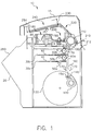
- a lathe bed scanner 10 of the present invention having a housing 15 for forming a protective cover.
- a movable, hinged door 20 is attached to a front portion of the housing 15 for permitting access to two media trays, a lower tray 30a and upper tray 30b, that are positioned in an interior portion of the housing 15 for supporting receiver material 40, typically paper, thereon.
- receiver material 40 typically paper
- the lower media tray 30a includes a cam 50a for lifting the paper 40 upwardly toward a rotatable, lower media roller 60a and, ultimately, toward a second rotatable, upper media roller 60b which, when both are rotated, permits the receiver material 40 to be pulled upwardly towards a media guide 70.
- the upper media tray 30b also includes a cam 50b for lifting the receiver material 40 toward the upper media roller 60b which directs it towards the media guide 70.
- the movable media guide 70 directs the receiver material 40 under a pair of rollers 80 which engages the receiver material 40 for assisting the upper media roller 60b in directing it onto a staging tray 90.
- the media guide 70 is attached and hinged to the interior of the housing 15 at one end, and is uninhibited at its other end for permitting multiple positioning of the media guide 70.
- the media guide 70 then rotates its uninhibited end downwardly, as illustrated by the solid line, and the direction of rotation of the upper media roller 60b is reversed for forcing the receiver material 40 resting on the staging tray 90 back under the rollers 80, upwardly through an entrance passageway 100 and around a rotatable imaging drum 110.
- each roll 120 includes a donor material 120 of a different color, typically black, yellow, magenta and cyan. These donor materials are ultimately cut into sheets and passed to the imaging drum for forming a medium from which dyes imbedded therein are passed to the receiver material resting thereon, which process is described in detail herein below.
- a drive mechanism 140 is attached to each roll 120, and includes three rollers 150 through which the donor material 120 of interest is rolled upwardly into a knife assembly 160.
- the rollers 150 cease driving the donor material 120 and two blades 170 positioned at the bottom portion of the knife assemble cut the donor material 120 into a sheet.
- the media rollers 60a and 60b and media guide 70 then pass the donor material 120 onto the drum 110 and in registration with the receiver material 40 using the same process as described above for passing the receiver material 40 onto the drum 110.
- the donor material 120 rests atop the receiver material 40 with a narrow gap between the two created by microbeads imbedded into the receiver material 40.
- a laser assembly 180 includes twenty lasers 185 in its interior, and these lasers are connected via fiber optic cables 187 to a coupling head 190 and ultimately to a print head 200.
- the print head 200 creates thermal energy from the signal received from the lasers 185 causing the donor material 120 to pass its dye across the gap to the receiver material 40.
- the print head 200 is attached to a lead screw 210 via a nut (not shown in Fig. 1) for permitting it to move axially along the longitudinal axis of the drum 110 for writing data onto the receiver material 40.
- the drum 110 rotates at a constant velocity, and the print head 200 begins at one end of the receiver material 40 and traverses the entire length of the receiver material 40 for completing the transfer process for the particular donor material resting on the receiver material 40.
- the donor material 120 is then transferred from the drum 110 and out of the housing 15 via a skive or ejection chute 210.
- the donor material eventually comes to rest on a donor material tray 212 for permitting removal by a user.
- the above-described process is then repeated for the other three rolls of donor material.
- the receiver material 40 is transported via a transport mechanism 220 through an entrance door 230 and into a dye binding assembly 240 where it rests against an exit door 250.
- the entrance door 230 is opened for permitting the receiver material 40 to enter into the dye binding assembly 240, and, shuts once it comes to rest in the dye binding assembly 240.
- the dye binding assembly 240 heats the receiver material 40 for further binding the transferred dye on the receiver material 40 and for sealing the microbeads thereon.
- the exit door 250 is opened and the receiver material 40 with the image thereon passes out of the housing 15 and comes to rest against a stop 260.
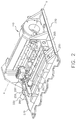
- FIG. 2 there is illustrated a perspective view of the imaging drum 110 and print head 200 of the lathe bed scanner 10.
- the imaging drum 110 is mounted for rotation about an axis (x) in a frame support 270.
- the print head 200 is movable with respect to the imaging drum 110, and is arranged to direct a beam of actinic light to the donor material 120 (shown in Fig. 1).
- the print head 200 contains therein a plurality of writing elements (not shown) which can be individually modulated by electronic signals from the laser diodes 185, which signals are representative of the shape and color of the original image, so that each dye is heated to cause volatilization only in those areas in which its presence is required on the receiver material 40 to reconstruct the color of the original object.
- the print head 200 is mounted on a movable translator member 280 which, in turn, is supported for low friction slidable movement on bars 290 and 300.
- the bars 290 and 300 are sufficiently rigid so that they do not sag or distort between the mounting points and are arranged as parallel as possible with the axis (x) of the imaging drum 110.
- the upper bar 300 is arranged to locate the axis of the print head 200 precisely on the axis (x) of the drum 110 with the axis of the print head perpendicular to the drum axis (x).
- the upper bar 300 locates the translator member 280 in the vertical and the horizontal directions with respect to the axis of the drum 110.
- the lower bar 290 locates the translator member 280 only with respect to rotation of the translator about the bar 290 so that there is no over-constraint of the translator member 280 which might cause it to bind, chatter, or otherwise impart undesirable vibration to the print head 200 during the generation of an image.
- the upper bar 300 is supported by a plurality of spaced-apart bosses 350 which are an integral part of the support frame 270, and a solid receiving receptacle 360, which is also integrally attached to the support frame 270, receives the lower bar 290 for supporting it within the support frame 270.
- the frame 270 includes two installation holes 295 on one end of the frame 270 that are respectively aligned with two installation holes 296 on the opposite ends of the frame 270 for permitting the bars 290 and 300 to be inserted and aligned therein during their installation.
- a lead screw 310 includes an elongated, threaded shaft 320 which is attached to a motor 330 on its driven end and to the frame support 270 at its driven end.
- a nut 340 includes grooves in its hollowed-out center portion for mating with the threads of the shaft 320 for permitting the nut 340 to move axially along the shaft 320 as the nut is rotated.
- the nut 340 is integrally attached to the print head 200 at its periphery so that, as the shaft 320 is rotated by the motor 330, the nut moves axially along the shaft 320 which, in turn, moves the print head 200 axially along the drum.
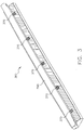
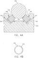
- a plurality of neodymium iron boron (NdFeB) magnets 370 are positioned along the longitudinal axis of the receptacle 360 respectively in a plurality of circular-shaped counterbored holes 380 for permitting the magnets 370 to receive the bar 290 by magnetic attraction.
- NdFeB neodymium iron boron
- Each magnet 370 is preferably positioned directly opposite another magnet 370 on the opposite side of the receptacle 360 for forming a mated pair.
- Each magnet 370 also preferably includes a magnetic force of substantially four and one-half pounds, and includes a keeper 390 magnetically attached on its bottom portion for enhancing the strength of the magnet 370.
- a plurality of plastic, circular-shaped alignment seals 400 respectively rest on a lip of a counterbore for abuttingly receiving the magnets 370.
- Each alignment seal 400 is sufficiently flexible so that the magnet is manually slidable into the seal, and is also sufficiently rigid so that once the magnet is in its desired position it is retained in this position until the below-described process for rigidly attaching the magnet 370 is completed.
- the seal 400 is preferably ten thousands of an inch in thickness, and each includes a slit 410 therein for permitting efficient installment of the magnets 370, as will be described in detail below.
- an installation rod having a substantially straight longitudinal axis (a tolerance of less than five microns) is initially installed on the receptacle 360 for aligning the magnets 370 in their desired positions; the installation rod is replaced after such initial alignment by commercially available rod 290.
- the installation rod is inserted into their respective installation holes and placed on the magnets 370.
- the installation rod is aligned parallel to the axis (x) of the imaging drum 110, by methods well known in the art. Since the installation rod is straight, the magnets 370 align themselves in a position defining a parallel axis to the axis (x) of the imaging drum for any rod placed thereon.
- a fill port 420 passes into the interior of the receptacle 360 and connects with each counterbore 380 for providing a passageway for a binding solution, such as stycast epoxy, to the counterbore 380 from the exterior.
- a binding solution such as stycast epoxy
- the binding solution is injected into the fill port 420 until the solution seeps through the slit 410 in the alignment seal 400 indicating that the portion of counterbore 380 beneath the alignment seal 400 is completely full.
- the seal 400 functions to contain the solution such that other counterbore orientations, upside down or horizontal orientations, may also be potted. After a period of time, the solution hardens thereby rigidly attaching the magnets 370 to the receptacle 360.
- any commercially available rod 290 which typically includes a curvature along its longitudinal axis is placed on the magnets 370.
- the magnets 370 each magnetically attract the surface of the commercially available rod 290 to which it is adjacent so that the longitudinal axis of the rod 290 becomes substantially straight and parallel to the axis (x) of the imaging drum.
- the method further comprising a fill port for permitting access to the cavity.
- the method further comprising providing a bar having a curvature therein on the magnet for altering the shape of the bar to substantially straight.
- a method for rigidly attaching a post to a support member comprising the steps of:
- step (b) includes providing a slit in the alignment seal for permitting visual indication of when the cavity is completely filled.
- step (b) includes providing means for indicating a level of the solution in the cavity.
- the method further comprising a fill port for permitting access to the cavity.
- the method further comprising providing a bar having a curvature therein on the magnet for altering the shape of the bar to substantially straight.
- An apparatus for maintaining the positional relationship of an element comprising:
- the apparatus further comprising a plurality of magnets for attracting said bar.
Landscapes
- Engineering & Computer Science (AREA)
- Multimedia (AREA)
- Signal Processing (AREA)
- Electronic Switches (AREA)
- Printers Or Recording Devices Using Electromagnetic And Radiation Means (AREA)
- Common Mechanisms (AREA)
Applications Claiming Priority (2)
| Application Number | Priority Date | Filing Date | Title |
|---|---|---|---|
| US08/667,775 US5838345A (en) | 1996-06-21 | 1996-06-21 | Apparatus for maintaining the positional relationship of a print head |
| US667775 | 1996-06-21 |
Publications (2)
| Publication Number | Publication Date |
|---|---|
| EP0814595A2 true EP0814595A2 (fr) | 1997-12-29 |
| EP0814595A3 EP0814595A3 (fr) | 1998-11-11 |
Family
ID=24679582
Family Applications (1)
| Application Number | Title | Priority Date | Filing Date |
|---|---|---|---|
| EP97201740A Withdrawn EP0814595A3 (fr) | 1996-06-21 | 1997-06-09 | Appareil pour maintenir la relation de position d'une tête d'impression |
Country Status (3)
| Country | Link |
|---|---|
| US (1) | US5838345A (fr) |
| EP (1) | EP0814595A3 (fr) |
| JP (1) | JPH1058725A (fr) |
Cited By (4)
| Publication number | Priority date | Publication date | Assignee | Title |
|---|---|---|---|---|
| EP0982147A2 (fr) | 1998-08-28 | 2000-03-01 | Eastman Kodak Company | Système magnétique pour le positionnement d'une tête d'impression dans un appareil de traitement d'image |
| EP0950526A3 (fr) * | 1998-04-15 | 2000-06-14 | EASTMAN KODAK COMPANY (a New Jersey corporation) | Vis sans fin réglable pour changer la résolution et pour corriger d'une station à l'autre, d'une machine à l'autre ou d'un balayage à l'autre |
| EP1182045A1 (fr) * | 2000-08-24 | 2002-02-27 | Hewlett-Packard Company, A Delaware Corporation | Poutre pour un chariot d'imprimante |
| EP1815999A3 (fr) * | 2006-02-03 | 2008-04-16 | Océ-Technologies B.V. | Guide pour guider un chariot mobile dans une direction d'impression, et imprimante |
Families Citing this family (7)
| Publication number | Priority date | Publication date | Assignee | Title |
|---|---|---|---|---|
| US6034713A (en) * | 1997-05-21 | 2000-03-07 | Eastman Kodak Company | Image processor having magnetically attached print head |
| US6037960A (en) * | 1998-03-31 | 2000-03-14 | Eastman Kodak Company | Direct write plates on a thermal dye transfer apparatus |
| US5973715A (en) * | 1998-06-04 | 1999-10-26 | Eastman Kodak Company | Image processing equipment |
| US6614463B2 (en) | 2001-10-05 | 2003-09-02 | Eastman Kodak Company | Image processing apparatus with conduit tube and blower |
| US6677975B1 (en) | 2002-06-19 | 2004-01-13 | Eastman Kodak Company | System and process for magnetic alignment of an imaging subsystem |
| US8182608B2 (en) * | 2007-09-26 | 2012-05-22 | Eastman Kodak Company | Deposition system for thin film formation |
| US8523318B2 (en) * | 2011-09-21 | 2013-09-03 | Eastman Kodak Company | Support for carriage guide in printer |
Family Cites Families (15)
| Publication number | Priority date | Publication date | Assignee | Title |
|---|---|---|---|---|
| US3907090A (en) * | 1974-02-19 | 1975-09-23 | Computer Devices Inc | Printer and pressure assembly therefor |
| DE2724855C2 (de) * | 1977-06-02 | 1982-05-27 | Kurt 7218 Trossingen Held | Gerät zum automatischen Beschriften von Zeichnungen |
| IT1160812B (it) * | 1983-03-21 | 1987-03-11 | Honeywell Inf Systems | Struttura meccanica di una stampante seriale |
| JPS61228996A (ja) * | 1985-04-03 | 1986-10-13 | 岩崎通信機株式会社 | ペン制御回路 |
| DE8807526U1 (de) * | 1988-06-09 | 1989-07-06 | Siemens AG, 1000 Berlin und 8000 München | Registriergerät mit einem quer zur Bewegungsrichtung eines Aufzeichnungsträgers bewegbaren Schreibwagen |
| US4932805A (en) * | 1988-07-28 | 1990-06-12 | Eastman Kodak Company | Method and apparatus for aligning and mounting machine components |
| US5260714A (en) * | 1991-08-23 | 1993-11-09 | Eastman Kodak Company | Method of removing air from between superposed sheets |
| US5301099A (en) * | 1991-08-23 | 1994-04-05 | Eastman Kodak Company | Vacuum imaging drum with a material receiving recess in the periphery thereof |
| US5276464A (en) * | 1991-08-23 | 1994-01-04 | Eastman Kodak Company | Method and apparatus for loading and unloading superposed sheets on a vacuum drum |
| US5278579A (en) * | 1991-08-23 | 1994-01-11 | Eastman Kodak Company | Optical fiber support and storage device |
| US5264867A (en) * | 1991-08-23 | 1993-11-23 | Eastman Kodak Company | Method and apparatus for selectively sorting image-bearing sheets from scrap sheets |
| US5270731A (en) * | 1991-08-23 | 1993-12-14 | Eastman Kodak Company | Laser thermal printer with positive air flow |
| DE69224020T2 (de) * | 1991-08-23 | 1998-08-13 | Eastman Kodak Co | Abbildungsgerät und Gewindespindelantrieb |
| US5195836A (en) * | 1991-10-29 | 1993-03-23 | Hewlett-Packard Company | Guideway and support structure for a printer/plotter carriage |
| US5575577A (en) * | 1993-04-30 | 1996-11-19 | Canon Denshi Kabushiki Kaisha | Recording apparatus having position detecting device |
-
1996
- 1996-06-21 US US08/667,775 patent/US5838345A/en not_active Expired - Lifetime
-
1997
- 1997-06-09 EP EP97201740A patent/EP0814595A3/fr not_active Withdrawn
- 1997-06-13 JP JP15695597A patent/JPH1058725A/ja active Pending
Cited By (5)
| Publication number | Priority date | Publication date | Assignee | Title |
|---|---|---|---|---|
| EP0950526A3 (fr) * | 1998-04-15 | 2000-06-14 | EASTMAN KODAK COMPANY (a New Jersey corporation) | Vis sans fin réglable pour changer la résolution et pour corriger d'une station à l'autre, d'une machine à l'autre ou d'un balayage à l'autre |
| EP0982147A2 (fr) | 1998-08-28 | 2000-03-01 | Eastman Kodak Company | Système magnétique pour le positionnement d'une tête d'impression dans un appareil de traitement d'image |
| EP1182045A1 (fr) * | 2000-08-24 | 2002-02-27 | Hewlett-Packard Company, A Delaware Corporation | Poutre pour un chariot d'imprimante |
| US6648529B2 (en) | 2000-08-24 | 2003-11-18 | Hewlett-Packard Development Company, L.P. | Hardcopy apparatus carriage beam |
| EP1815999A3 (fr) * | 2006-02-03 | 2008-04-16 | Océ-Technologies B.V. | Guide pour guider un chariot mobile dans une direction d'impression, et imprimante |
Also Published As
| Publication number | Publication date |
|---|---|
| EP0814595A3 (fr) | 1998-11-11 |
| US5838345A (en) | 1998-11-17 |
| JPH1058725A (ja) | 1998-03-03 |
Similar Documents
| Publication | Publication Date | Title |
|---|---|---|
| US5838345A (en) | Apparatus for maintaining the positional relationship of a print head | |
| DE69126475T2 (de) | Kompakter Lese-/Druck-Abtaster | |
| DE69122993T2 (de) | Ein- und Ausgangsabtaster | |
| DE69119487T2 (de) | Tragbarer Kopierer | |
| EP1068958A2 (fr) | Méthode et dispositif de positionnement d'un ensemble d'écriture d'un appareil de traitement d'images | |
| DE69124430T2 (de) | Abtaster mit Mitteln zur Registrierung von Vorlagen und Kopieblättern | |
| US5829889A (en) | Method and apparatus for magnetically preloading a ball bearing assembly | |
| US6332734B1 (en) | Method and apparatus for mounting a supply roll or recording media to a support shaft in an imaging system | |
| US5818497A (en) | Apparatus for magnetically coupling a lead screw to a print head | |
| DE69213838T2 (de) | Dokumentenabtaster und -drucker mit einfacher Konstruktion für manuelle Blattzufuhr | |
| US5997119A (en) | Magnetic arrangement for printhead positioning in an image processing apparatus | |
| US6037960A (en) | Direct write plates on a thermal dye transfer apparatus | |
| US5812175A (en) | Laser thermal printer with reversible imaging drum rotation for printing mirror images | |
| US5771059A (en) | Apparatus for preventing axial movement of a lead screw | |
| EP1375168B1 (fr) | Système et procédé d'alignement magnétique pour un sous-système d'imagerie | |
| US6034713A (en) | Image processor having magnetically attached print head | |
| US6208368B1 (en) | Removable lead screw assembly for an image processing apparatus | |
| EP0982142B1 (fr) | Méthode et dispositif pour fournir une force de charge pour ajuster une tête d'impression grâce à des aimants | |
| US6400387B1 (en) | Lathe bed scanning engine with adjustable bearing rods mounted therein | |
| US5949466A (en) | Exposing imagesetter recording film to a dye collection sheet on a transfer apparatus | |
| US5949463A (en) | Image processor for processing various sizes of a processing medium | |
| US6313859B1 (en) | Method and apparatus for axial direction sheet feed to a vacuum drum | |
| US5291217A (en) | Method and apparatus for producing thermal slide transparencies | |
| US6515691B2 (en) | Lead screw and write engine using same | |
| US6614463B2 (en) | Image processing apparatus with conduit tube and blower |
Legal Events
| Date | Code | Title | Description |
|---|---|---|---|
| PUAI | Public reference made under article 153(3) epc to a published international application that has entered the european phase |
Free format text: ORIGINAL CODE: 0009012 |
|
| AK | Designated contracting states |
Kind code of ref document: A2 Designated state(s): DE FR GB |
|
| PUAL | Search report despatched |
Free format text: ORIGINAL CODE: 0009013 |
|
| AK | Designated contracting states |
Kind code of ref document: A3 Designated state(s): AT BE CH DE DK ES FI FR GB GR IE IT LI LU MC NL PT SE |
|
| 17P | Request for examination filed |
Effective date: 19990414 |
|
| AKX | Designation fees paid |
Free format text: DE FR GB |
|
| 17Q | First examination report despatched |
Effective date: 20030512 |
|
| STAA | Information on the status of an ep patent application or granted ep patent |
Free format text: STATUS: THE APPLICATION IS DEEMED TO BE WITHDRAWN |
|
| 18D | Application deemed to be withdrawn |
Effective date: 20031125 |