EP0814603A2 - Verfahren zur Bestimmung der Belichtung zum Kopieren eines Digitalbildes - Google Patents
Verfahren zur Bestimmung der Belichtung zum Kopieren eines Digitalbildes Download PDFInfo
- Publication number
- EP0814603A2 EP0814603A2 EP97109849A EP97109849A EP0814603A2 EP 0814603 A2 EP0814603 A2 EP 0814603A2 EP 97109849 A EP97109849 A EP 97109849A EP 97109849 A EP97109849 A EP 97109849A EP 0814603 A2 EP0814603 A2 EP 0814603A2
- Authority
- EP
- European Patent Office
- Prior art keywords
- digital
- image
- exposure amount
- color
- information
- Prior art date
- Legal status (The legal status is an assumption and is not a legal conclusion. Google has not performed a legal analysis and makes no representation as to the accuracy of the status listed.)
- Withdrawn
Links
Images


Classifications
-
- H—ELECTRICITY
- H04—ELECTRIC COMMUNICATION TECHNIQUE
- H04N—PICTORIAL COMMUNICATION, e.g. TELEVISION
- H04N1/00—Scanning, transmission or reproduction of documents or the like, e.g. facsimile transmission; Details thereof
- H04N1/46—Colour picture communication systems
- H04N1/56—Processing of colour picture signals
- H04N1/60—Colour correction or control
- H04N1/603—Colour correction or control controlled by characteristics of the picture signal generator or the picture reproducer
Definitions
- the present invention relates to an image outputting method, a digital exposure amount image information calculating method, a converting information producing method, a converting information recording medium, and an image outputting system.
- the digital exposure used hereinafter means that an image exposure is conducted based on digital image signals so as to form an image.
- the digital exposure is not limited by a specific exposing means. That is, as an exposure means for the digital exposure, a scanning exposure means with a laser beam, a one dimensional exposure means with a single array light source in which plural light emitting elements such as LEDs are aligned in a line, a two dimensional exposure means with plural array light sources, a projecting exposure means with a CRT screen and so on may be used.
- a color negative film is formed with sublimation type pigment image by using a sublimation type thermal transfer printer, a color image is exposed and printed from the color negative film onto a color printing photosensitive material, thereby obtaining the color prints.
- a silver halide color negative photographic film used for photographing is subjected to digital exposure on the basis of B,G,R digital image information and a color negative film is obtained by developing the exposed silver halide color negative photographic film. Then, a color image is exposed and printed from the color negative film onto a color printing photosensitive material, thereby obtaining the color prints.
- This technique is similar to Conventional technique 3. That is, in conventional technique 5, a silver halide color negative photographic film used for photographing is subjected to digital exposure on the basis of digital image information and a color negative film is obtained by developing the exposed silver halide color negative photographic film. Then, a color image is exposed and printed from the color negative film onto a color printing photosensitive material, thereby obtaining the color prints. It may be consider for an ordinary person in view of this technique to record an image by utilizing all recordable density region of the negative film. However, how to use the density region is not clear.
- This technique is also similar to Conventional technique 3. That is, in conventional technique 5, a silver halide color negative photographic film used for photographing is subjected to digital exposure on the basis of digital image information and a color negative film is obtained by developing the exposed silver halide color negative photographic film. Then, a color image is exposed and printed from the color negative film onto a color printing photosensitive material, thereby obtaining the color prints.
- a synthesized image of a pattern image and a photographic image is formed on a silver halide negative photographic film by digital exposure on the basis of pattern image information and digital photographic image information, it may be difficult for an ordinary person in view of this technique to consider to separate the density range of the pattern image from the density range of the photographic image.
- the first objective of the present invention is to make it easy to deal with the fluctuation in the exposure level of the digital exposure of the image outputting means, the fluctuation in the developing level or the deviation in the characteristics among lot of the photosensitive materials.
- the technique of Conventional technique 3 may come to attention.
- the following problems may be pointed out for the silver halide photographic color negative film. It may be necessary to subtract the influence of sub-absorption of color dies constituting an image on the silver halide photographic color negative film. There may be deviation between an actual image seen from an object by eyes and a memory image of the object or deviation between an actual color of the object and memory color. Developing effect among photosensitive layers generally takes place due to the reason that peoples usually like prints reproduced brightly.
- the developing effect among photosensitive layers is an effect to refrain another primary color from coloring for exposure to color a specific primary color.
- the similar correction to the developing effect among photosensitive layers has been already applied to B.G.R digital image information. Therefore, in the step of producing a color negative film, if the developing effect among photosensitive layers is further applied, the developing effect among photosensitive layers becomes strong excessively. As a result, chrome is so overemphasized that abnormal color prints color differently from original color are produced.
- the second objective of the present invention is to correct the influence of the developing effect among photosensitive layers so as to prevent chroma from being overemphasized due to the developing effect among photosensitive layers so that abnormal prints may be avoided and color prints with a natural feeling can be obtained.
- the third objective of the present invention is to avoid the special problems of the digital exposure so as to make it easy to obtain good prints.
- the fourth objective is to make it possible by avoiding the special problem of the digital exposure to obtain a print on which a pattern image is formed in a sharp image capable of being discriminated from a photographic image even if a synthesized image of the pattern image and the photographic image is printed.
- color digital image information expressed in an arbitrary color space system monochromatic digital image information may be used or color digital image information composed of plural primary colors may be used.
- color digital image information used as the digital image information expressed in an arbitrary color space system not only digital image information expressed in R,G,B color space system such as digital image information which is detected from original image by a scanner and is expressed in R,G,B density, digital image information which is detected from an object by photographing elements and is expressed in R,G,B density, and digital image information which is expressed in R,G,B input signals so as to be displayed on the monitor, but also digital image information expressed in CIELAB chromaticity coordinate, digital image information expressed in CIELUV chromaticity coordinate, and digital image information expressed in CIEXYZ chromaticity coordinate may be used.
- a photosensitive material As a photosensitive material, a photographing photosensitive material, a printing photosensitive material, a copying photosensitive material are listed from the view point of the use. Further, a silver halide photosensitive material and an electrophotographic photoreceptor are listed from the view point of the material.
- the silver halide photosensitive material may preferable in terms of sharpness, gradation and color reproducibility.
- an image obtained by developing the photosensitive material may be named as a developed image.
- photographing photosensitive material a photographing photosensitive film, a photographing photosensitive glass and a photographing photosensitive paper are listed.
- printing photosensitive material a photographic paper and a printing film are listed.
- an apparatus which conducts projecting exposure from CRT to emit light in accordance with digital image information to the photosensitive material so as to output an image an apparatus which conducts projecting exposure from CRT to emit light in accordance with digital image information to the photosensitive material so as to output an image and an apparatus which conducts projecting exposure from TFT elements to change cell density in accordance with digital image information to the photosensitive material so as to output an image are listed.
- the digital exposure amount information is information to define a digital exposure amount. It may be the digital exposure amount itself, a logarithmic digital exposure amount (a logarithm of a digital exposure amount) or a relative value of a digital exposure amount.
- the digital exposure amount image information a digital image information expressed by the digital exposure amount information.
- the digital input value is an digital input value inputted to the image outputting means.
- the digital input value image information is a digital image information expressed by the digital input value inputted to the image outputting means.
- the image outputting means outputs an image in accordance with the digital input value image information. If the digital input value and the digital exposure amount provided to the photosensitive material by the image outputting means are entirely the same as each other, there may be no problem. However, they are not likely to be the same, and they are not even in a linear relationship.
- the converting information to convert the digital exposure amount information to the digital input value for the image outputting means to output an image by conducting digital exposure onto the photosensitive material based on the digital input value image information may be in all possible form.
- information of matrix to approximately convert the digital exposure amount information to the digital input value for the image outputting means to output an image by conducting digital exposure onto the photosensitive material or data of three dimensional LUT to convert the digital exposure amount information to the digital input value for the image outputting means to output an image by conducting digital exposure onto the photosensitive material may be used as the converting information.
- another form may be used as the converting information.
- Density information is defined to be information which stipulates optical density, which may either be density itself or reflection ratio, transmissive ratio or light absorption ratio.
- density image information is defined to be digital image information represented by density information.
- Information which shows relationship between digital exposure amount information given to a light-sensitive material and density information of developed image generated by the given digital exposure amount information may take any style. For example, information of function for each primary color for approximately converting the digital exposure amount information given to the light-sensitive material to density information of developed image generated by the given digital exposure amount information may be used. In addition, 3-D LUT data for converting exposure amount information given to the light-sensitive material to the density information of developed image generated by the given digital exposure amount information may be used. Other styles may be used.
- Information which shows relationship between the digital input value to an image outputting means and density information of developed image generated by the given digital input value may take any style. For example, information of function for each primary color for approximately converting the digital input value to density information of developed image generated by the given digital input value.
- 3-D LUT data for converting the digital input value to an image outputting means density information of developed image generated by the given digital input value may be used. Other styles may be used.
- the kind of light-sensitive material is defined to be kind in accordance with image property such as light-sensitive property and coloring property.
- B, G and R digital image information may be digital image information temporarily converted to B, G and R digital image information from color digital image information expressed by means of an arbitrary color space system such as digital image information expressed by means of a CIELAB chromaticity coordinate, digital image information expressed by means of a CIELUV chromaticity coordinate or digital image information expressed by means of a CIEXYZ chromaticity coordinate.
- a silver halide color negative photographic film for photographing use one or plural silver halide emulsion light-sensitive layers for each primary color are provided on a film support.
- Most of aforesaid films for photographing contain developing effects among photosensitive layers due to reasons that: influence by the sub-absorption of a dye which constitutes the image of the silver halide color negative photographic film for photographing is subtracted; difference between an image of an object actually viewed and an image of an object memorized (difference of colors memorized and colors of actual object); ordinarily, a person likes prints vividly reproduced.
- a silver halide color negative photographic paper for printing use one or plural silver halide emulsion light-sensitive layer for each primary color are provided on a film support. In this case, the developing effects among photosensitive layers is only ignorable.
- Information for correcting and converting developing effects among photosensitive layers is information for correcting influence from the developing effects among photosensitive layers of the silver halide color negative photographic film for photographing. Any type may be used. For example, information of function for each primary color for approximately converting B, G and R digital image information prior to correcting the influence from developing effects among photosensitive layers to B, G and R B, G and R digital image information after influence from the developing effects among photosensitive layers was corrected . In addition, 3-D LUT data for converting B, G and R digital image information prior to correcting the influence from developing effects among photosensitive layers to B, G and R B, G and R digital image information after influence from the developing effects among photosensitive layers was corrected. Other styles may be used.
- a film recorder As a device to digitally expose the silver halide light-sensitive color negative photographic film for photographing, a film recorder is conventional.
- Sensitometry is defined to show correspondence between digital exposure amount information given to the light-sensitive material and density information of developed image obtained from a light-sensitive material exposed. Sensitometry property due to exposure on a silver halide color negative photographic film for photographing for plural of different colors is defined to be sensitometry property.
- Neutral color is referred to as that the amount of B, G and R light is equal each other.
- B, G and R are three primary colors of light, B, G and R.
- Y, M and C are respectively light in which two of B, G and R are mixed in an equal amount and the remaining one color is mixed negligibly.
- neutral color is based on R, G, B density obtained by exposing achromtaic wedge exposure with CIE C, D50 or D65 light source and by developing.
- Neutral color relationship is referred to as that when B, G, R exposures which are usually conducted separately sequentially are conducted simultaneously, if the B, G, R exposures form neutral color, the B, G, R exposures are in the neutral color relationship.
- a color negative photographic film may be a color negative photographic film made of other elements, in addition to a silver halide color negative photographic film.
- Density area capable of being recorded on a silver halide color negative photographic film is a density area capable of being recorded on a color negative film obtained by photographically processing the silver halide color negative photographic film. Density area capable of being recorded on the silver halide color negative photographic film is different for each of B, G and R. Ordinarily, the lower limit is 0 - 1.0, and the upper limit is 1.8 - 3.5. However, these are not limited to the above-mentioned values. Density area of both ends capable of being recorded on a silver halide color negative photographic film are area referred to as "toe" and "shoulder” in which contrast is recorded low (soft). Toe portion has unfavorable graininess. However, in ordinary photographing and printing, the above-mentioned density area is utilized to be recorded.
- Pattern image information is not necessarily digital pattern image information. It may be text-type character image information.
- a synthetic image composed of a pattern image and a photographic image the pattern image and the photographic image may be superposed, and may be separated.
- a photographic image is synthesized with a pattern image, not only one sheet of photographic image, but also plural photographic images may be synthesized.
- plural pattern images may be synthesized. It goes without saying that the pattern image includes a picture image, symbol image and a mathematics symbol image.
- the pattern image When a pattern image is recorded at density distinct from the density area in which the photographic image is recorded, the pattern image may be recorded at density distinct from the density of the photographic image at an extent of discriminable. It is preferable that the distinction of density is, in conversion to logalism exposure amount, 0.02 or more (specifically, 0.05 or more) and 0.2 or less (specifically 0.1 or less).
- a storing medium recording media such a magnetic recording medium including a floppy disc and a magnetic tape, optical recording medium including CD-ROM and optical magnetic recording medium such MO and RAM chip and IC card in which batteries are backed up and ROM chip are cited.
- a storing medium an RAM backed up by a battery and uninvolatile storing medium are preferable since modification of setting is easy because separation and replacement are easy and re-write can be conducted and aforesaid medium can easily be supplied to plural printing systems.
- memory may be stored in a storing device such as a hard disc on a personal computer. For such purposes, data may be transferred through a network.
- the memory may be stored in a part of computer connected to the network, and successively it may be transferred to the network. For example, conversion information produced and stored in America may successively be transferred to users in Japan.
- Each conversion information may be obtained in an image outputting system by a customer. However, it is preferable to be produced accurately in advance in a factory or a marketing agent by the use of an image outputting system having identical properties as the image outputting system of the customer. It is also preferable that each of the resulting conversion information is passed through a communication circuit, or is stored in a portable storing medium or is integral in the image outputting system in advance to be supplied. Since it is possible promptly forward each of conversion information calculated in Australia or Canada to customers in Japan or England, it is preferable to supply it through a communication circuit such as a network. Conversion information forwarded through a communication circuit or stored in a storing medium can be stored/forwarded in such a manner that conversion information for each of light-sensitive material can be used as it is or coded to be forwarded.
- Fig. 1 shows a schematic block diagram of an image outputting system of Embodiment 1.
- Fig. 2 shows a schematic block diagram of an image processing apparatus of an image outputting system of Embodiment 1.
- Fig. 3 shows a schematic block diagram of a film recorder of an image outputting system of Embodiment 1.
- Fig. 4 shows a flow diagram in Embodiment 1 until the LUT data of the digital input value conversion LUT is prepared and aforesaid LUT data is stored on a conversion information storing medium.
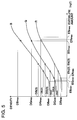
- Fig. 5 is a drawing showing an example of the characteristics curves of Embodiment 1.
- Fig. 6 is a drawing showing an example of a film for setting a conversion table of Embodiment 1.
- Fig. 7 is a drawing showing relationship between the digital input value and density obtained by Embodiment 1.
- Fig. 8 is a drawing showing relationship between the digital input value and digital input value obtained by Embodiment 1.
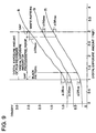
- Fig. 9 is a drawing showing relationship between the digital exposure area of a film recorder, digital exposure area of photographic image and digital exposure amount of pattern image and their densities obtained by Embodiment 1.
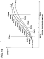
- Fig. 10 is a drawing for showing a characteristic curve by means of G color and a neutral color exposure, a characteristic curve by means of G exposure and a characteristic curve by means of a Y exposure for explaining a method of digital exposure amount providing equal densities each other from characteristic curve related to B, G, R, Y, M and C exposure other than neutral exposure about each of neutral exposure amount selected by Embodiment 1.
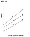
- Fig. 11 is a drawing showing B, G and R densities reproduced from B, G and R digital exposure amount in Embodiment 2.
- Fig. 12 shows a schematic block diagram of an image outputting system of Embodiment 4.
- An image outputting system of the present embodiment is a practical example of the present invention, in which, namely, color digital photographic image information which has been inputted from an inputting device such as a reflective original scanner and which is expressed in an arbitrary color space system is subjected to image processing. If necessary, aforesaid image outputting system of the present embodiment is subjected to image synthesis processing with pattern image information such as character image. Then, the signal of the digital input value is outputted to a film recorder, by which the signal is then subjected to digital exposure on a light-sensitive film for copying. The film for copying subjected to digital exposure is subjected to photographic processing. From the resulting film for copying, printing is obtained on a color photographic paper with a printer processor.
- the apparatus of the present embodiment will be detailed.
- Fig. 1 shows a schematic block diagram of the present image outputting system.
- An image inputting device in the present image outputting system is composed of: reflection original scanner 93 which image-senses a reflection image on a reflection original and which obtains color digital photographic image information, transmission original scanner 94 which image-senses a transmission image on a transmission original and which obtains color digital photographic image information, image information recording media reading device 95 which obtains color digital photographic image information or pattern image information which is recorded onto color digital image information recording medium and electronic camera 96 which captures an image of an object and which converts it to color digital photographic image information.
- Aforesaid inputting device is connected to image processing device 3 by means of a SCSI-II, and send the resulting color digital image information to image processing device 3.
- image processing device 3 may be inputted into image processing device 3 through the network.
- MO drive and MO As a combination of image information recording medium reading device 95 and color digital image information recording medium, MO drive and MO, CD-ROM drive and Photo-CD, Picture-MD drive and Picture-MD and memory card reader and memory card are cited.
- Image processing device 3 is connected to monitor 98 by means of monitor sending line 97, and is also connected to keyboard 91. It is also connected to converted information storing medium reading device 92, and also connected with densitometer 7 by means of density signal sending line 79. In addition, it is further connected to film recorder 5 by means of digital input value signal sending line 59. Based on converted information stored in the converted information storing medium read by converted information storing medium reading device 92, exposure amount image information is inputted into film recorder 5 through sending line 59 in accordance with operation of keyboard 91 while an image subjected to image processing is displayed onto monitor 98. Film recorder 5 converts digital exposure amount image information to digital input value image information and digitally exposes an image on a light-sensitive film for copying based on the resulting digital input value image information.
- Light-sensitive film 11 which has been digitally exposed is subjected to photographic processing by means of film processing machine 6 to be film 12 for copying.
- Aforesaid film is set to a printing mask section of printer processor 8, and then, printed and exposed on a color photographic paper.
- Printer processor 8 subjects a color photographic paper to photographic processing printed and exposed from film 12 for copying to obtain print 2.
- Film for copying 1 which has been printed and exposed in a printing and masking section is cut into lengths of 2 or more frames. These are recorded as at least one frame in a cut piece.
- film recorder 5 forms one frame of the latent image and all latent images for order information 16 and printing quantity information 17 on an area corresponding to ordinary 2 frames of light-sensitive film for copying.
- FIG. 2 is a schematic block diagram of an image processing apparatus
- image processing apparatus 3 Each section of image processing apparatus 3 is controlled by central control section 49.
- Keyboard 91 is connected to this central control section 49 in such a manner that information through key inputting from keyboard 91 is inputted.
- Central control section 49 sends converted information which has been stored in a converted information storing medium read by converted information storing medium reading device 92 to an appropriate section in accordance with the kind of converted information so that it controls in such a manner that each section converts information based on the updated conversion information.
- Color digital image information inputted in image processing apparatus 3 is received by digital image information receiving section 31 and forwarded to digital image information assortment section 32.
- Digital image information sorting section 32 sends received color digital image information to an appropriate section in accordance with the kind of received color digital image information. Namely, color digital photographic image information which has already been subjected to providing with appropriate color stain removal processing in an image inputting device side proceeds to digital image information storing section 34. On the contrary, color digital photographic image information which has already been subjected to providing an appropriate color stain removal processing on an image inputting device side and color digital photographic image information which has already been subjected to providing color stain removal processing at all are sent to color stain removal section 33. If the color digital image information is pattern image information such as a template image, aforesaid information is sent to template image storing section 42. Incidentally, "template image” is an image for design which may be reused.
- Color stain removal section 33 removes color stains in the received color digital photographic image information and sends color digital photographic image information from which color stains are removed to digital image information storing section 34.
- Digital image information storing section 34 stores received color digital photographic image information. When a digital input value is completely sent to outputted signal sending section 40, it sends color digital image information for one frame stored to film density conversion section 35.
- an external hard disc provided outside the apparatus may auxiliarily be used.
- Film density conversion section 35 converts the received color digital photographic image information to B, G and R film density photographic image information. Aforesaid B, G and R film density photographic image information is sent to color correction section 36.
- the film density photographic image information corresponds to print exposure amount photographic image information, and is approximately equal to the relative value of the exposure amount on a color photographic paper.
- Color correction section 36 conducts color correction of the received film density photographic image information. Aforesaid film density photographic image information subjected to color correction is sent to digital exposure amount conversion section 37.
- the received film density photographic image information is converted to digital exposure amount photographic image information based on the digital exposure amount conversion LUT for B, G and R formed based on the conversion LUT data of the digital exposure amount conversion information which is conversion information to convert B, G and R film density photographic image information to the digital exposure amount photographic image information.
- the film density photographic image information is converted to the digital exposure amount photographic image information.
- the LUT data of aforesaid digital exposure amount conversion LUT can be obtained from the characteristics curve of a light-sensitive material which is digitally exposed to light.
- Aforesaid digital exposure amount conversion LUT is read to be obtained what is stored in a conversion information storing medium as digital exposure amount conversion information by means of converted information storing medium reading device 92.
- the resulting B, G and R digital exposure amount photographic image information is sent to synthesizing processing section 38.
- Synthesizing processing section 38 sends B, G and R digital exposure amount photographic image information as the digital exposure amount image information as it is to developing effect among photosensitive layers correction section 39 based on information inputted by a keyboard.
- synthesizing processing section 38 synthesizes a template image sent from template image selection section 43 or character image information sent from character image information generating section 44 and, then, sent the resulting B, G and R digital exposure amount image information to developing effect among photosensitive layers correction section 39.
- B, G and R digital exposure amount photographic image information sent to synthesizing processing section 38 from digital exposure amount conversion section 37 is further sent to monitor signal conversion section 45.
- monitor signal conversion section 45 aforesaid B, G and R digital exposure amount photographic image information is converted to B, G and R monitor signals.
- Aforesaid monitor signals are sent to monitor 98 from monitor sending section 46 so that a photographic image is caused to be displayed on the monitor.
- central control section 49 produces keyboard inputting information 47.
- Template image selection section 43 selects the template image which corresponds to the template image selected based on keyboard information 47 from the template image stored in template image storing section 42 and sends it to synthesizing section 38.
- character image producing section 44 produces character image based on keyboard information 47 and sends it to synthesizing section 38.
- Synthesizing processing section 38 synthesizes a pattern image such as a template image and a character image sent and B, G and R digital exposure amount photographic image information by means of a synthesizing and processing method described later, and sends it to developing effect among photosensitive layers correction section 39.
- Developing effect among photosensitive layers correction section 39 obtains B, G and R digital exposure amount image information (B, G and R 8 bit gradation image information) wherein influence by developing effects among photosensitive layers is corrected from B, G and R digital exposure amount image information sent based on developing effect among photosensitive layers exposure correction amount calculation LUT which is a B, G and R 3-D LUT formed based on converted LUT data of developing effect among photosensitive layers correction conversion information which is information for conversion of correcting influence by developing effects among photosensitive layers, and sends it to outputted signal sending section 40.
- converted LUT data of developing effect among photosensitive layers exposure correction amount calculation LUT is calculated by a method described later.
- Outputted signal sending section 40 sends B, G and R digital exposure amount image information wherein influence by developing effects among photosensitive layers has been corrected to film recorder 5 from sending line 59.
- Fig. 3 is a schematic block diagram of film recorder.
- control section 55 controls each section based on information from each section.
- control signal is sent from image processing apparatus 3 through sending line 59
- outputted signal receiving section 58 sends the control signal to control section 55.
- Control section 55 conducts control depending upon such.
- the control includes setting of the digital input value conversion LUT for B, G and R formed based on the conversion LUT data of the digital input value conversion information onto digital input value conversion section 57, when conversion LUT data of digital input value conversion information which is information for converting digital exposure amount to the digital input value is sent.
- Outputted signal receiving section 58 receives B, G and R digital exposure amount image information (B, G and R 8 bits image information) sent from image processing apparatus 3 through sending line 59 wherein influence by developing effects among photosensitive layers has been corrected, and sends it to digital input value conversion section 57.
- Digital input value conversion section 57 obtains B, G and R digital input value image information (B, G and R 12 bits gradation image information) from B, G and R digital exposure amount image information sent based on the digital input value conversion LUT for B, G and R formed based on the conversion LUT data of digital input value conversion information which is information for converting digital exposure amount to digital input values, and sends it to D/A conversion section 56.
- the conversion LUT data of digital input value conversion information will be calculated by a method to be described later.
- D/A conversion section 56 converts received B, G and R digital input value image information (B, G and R 12 bits gradation image information) to analogue signals in the order of B, G and R.
- Monochrome CRT 51 for digital exposure is caused to display a monochrome image which corresponds to B, G and R image for exposure.
- Exposure lens 53 is located in such a manner that the monochrome image displayed on monochrome CRT 51 for digital exposure is image-formed on silver halide color negative light-sensitive film 11 for copying.
- an image to be copied is digitally exposed on silver halide color negative light-sensitive film 11 for copying.
- Fig. 4 is a flow diagram since LUT data of the digital input value conversion LUT is prepared until aforesaid data is stored in the conversion information storing medium
- the flow since LUT data of the digital input value conversion LUT is prepared until aforesaid data is stored in the conversion information storing medium will be explained.
- the kind of light-sensitive film for copying use which will be the standard for preparing the digital input value conversion LUT is selected, and then, start the operation. Advance to S11.
- a light-sensitive film for copying purely light-sensitive film for copying may be used.
- a light-sensitive film for ordinary photographing may also be substituted therefor.
- a reversal light-sensitive film or a negative light-sensitive film may be used.
- a color light-sensitive film or a monochrome light-sensitive film may be used.
- LV100 produced by Konica Corporation (trade name) will be used.
- characteristics curves of LV100 (the trade name) produced by Konica Corporation in accordance with densitometer 7 to be used are prepared, and then, the process advances to S12. These characteristic curves show the relationship between exposure amount (logE scale) and density measured by densitometer 7.
- densitometer 7 is an X-Rite 811 TR (the trade name), which conducts measurement using the status M of the X-Rite 811 TR (the trade mark).
- Fig. 5 shows an example of aforesaid characteristic curves. In Fig. 5, the vertical axis represents density value, and the horizontal axis represents exposure amount.
- a latent image of a step chart which is an image for setting a conversion table is formed on light-sensitive film 14 for setting a conversion table is formed, and then, the process advances to S13.
- one roll of LV100, (the trade mark) produced by Konica Corporation is used as light-sensitive film 14 for setting a conversion table on which the latent image of the step chart based on multi-steps of digital input value for obtaining the second information which shows the relationship between the digital input value and the density information of the developed image of LV100, (the trade mark) produced by Konica Corporation, generated by the above-mentioned digital exposure amount is formed, on which the latent image of the step chart based on multi-steps of digital input value is formed.
- Fig. 6 shows an example of film 15 for setting a conversion table wherein the latent image of the step chart is formed and developed.
- film 15 for setting a conversion table in each frame, one density measurement regions 16 is provided at the center of each frame.
- a prescribed exposure region 17 in which a prescribed exposure amount has been exposed is provided on the other area of each frame.
- the prescribed exposure region 17 is provided with an exposure amount of 10 to 50 % of the effective exposure amount.
- the effective exposure amount is defined as the difference between the maximum exposure amount to obtain the lowest density and the minimum exposure amount to obtain the highest density.
- the exposure amount of 10% of the effective exposure amount is obtained by adding 10% of the effective exposure amount into the maximum exposure amount to obtain the lowest density.
- the prescribed exposure region 17 is defined to be exposed with the exposure amount corresponding to output signal of 64. R, G, B exposures having a neutral color relationship are conducted separately on the density measurement regions 16 for each frame with continuously changed digital input values.
- the first frames are exposed with B,G,R exposure by the digital input value "0"
- the second frames are exposed by the digital input value "9”
- the third framed are exposed by the digital input value "18” and so on.
- the prescribed exposure region 17 is exposed with the fixed digital input value of 64.
- the digital input value for the prescribed exposure region 17 may be changed in such a manner that the averaged exposure value of the density measurement region 16 and the prescribed exposure region 17 becomes 25%.
- a non-exposure area may be provided in a bar shape in such a manner as a white bar for clearly providing a border between density measurement regions 16 and prescribed exposure region 17 when exposure amount ratio of the density measurement regions 16 to the prescribed exposure region 17 is 1.0.
- B,G,R measurement density values on all density measurement regions 16 of film 15 for setting a conversion table are in the neutral color relationship respectively. If B,G,R measurement density values on a part of density measurement regions among all density measurement regions 16 of film 15 for setting a conversion table are not in the neutral color relationship, the process proceeds to S16. If B,G,R measurement density values on all density measurement regions 16 of film 15 for setting a conversion table are respectively in the neutral color relationship for each of digital input value, the process (flow chart) is ended.
- the relationship between the digital input value and the density is calculated for each of B, G and R from B, G and R digital input value of each density measurement regions 16 wherein the latent image was formed at S12 and B, G and R densities of each density measurement regions 16 measured and obtained at S14, and then, the process advances to S17.
- Fig. 7 shows the relationship between the resulting digital input value and the density.
- the vertical axis represents density and the horizontal axis represents digital input value.
- the minimum neutral exposure amount ENmin is obtained, and then, the process advances to S18.
- B,G,R densities measured at S14 from the density measurement regions exposed with the minimum exposure amount among the density measurement regions 16 exposure amounts corresponding to the B,G,R densities respectively are obtained from the characteristic curves obtained at S11.
- the maximum exposure amount among the obtained exposure amounts is defined as the minimum neutral exposure amount ENmin.
- the density measurement regions exposed with the minimum exposure amount among the density measurement regions 16 is density measurement regions 16A in which the B, G and R digital input values are respectively zero.
- a required density range is not obtained depending on the kind of a negative film when a LUT for outputting is obtained for the negative film by the beformentioned method.
- Such a case occurs so often when the negative film is a soft tone type film whose ⁇ -portion (a straight line portion) on the characteristic curve is relatively short.
- a slope on foot portion is relatively long, such a case may occurs so often.
- the digital exposure amount signals are defined in such a manner that a center value of a range of image signals is adjusted so as to fit with a center point between the reproducible highest density and the lowest density.
- the density change for the exposure change becomes a predetermined relationship
- the production of LUT is started.
- the maximum neutral exposure amount ENmax is obtained, and then, the process advances to S19.
- the density measurement regions exposed with the maximum exposure amount among the density measurement regions having B,G,R densities higher than that of the density measurement regions exposed with a exposure amount smaller one step in the step chart of the density measurement regions 16 are used as the maximum neutral density measurement regions.
- B,G,R densities measured at S14 from the maximum neutral density measurement exposure amounts corresponding to the B,G,R densities respectively are obtained from the characteristic curves obtained at S11.
- the minimum exposure amount among the obtained exposure amounts is defined as the maximum neutral exposure amount ENmax.
- B,G,R densities in the i-th density measurement regions are DB(i), DG(i), DR(i), in order to satisfy the condition that the n-th density measurement regions having densities of DB(n), DG(n), DR(n) corresponds to the density measurement region having B,G,R densities higher than densities of DB(n-1), DG(n-1), DR(n-1) of the density measurement regions exposed with the exposure amount smaller by one step, it is necessary to satisfy the following conditional expressions.
- the density measurement regions exposed with the maximum exposure amount among the density measurement regions satisfying the condition is used as the maximum neutral density measurement region. Since usually digital exposure amount is simply increased with the digital input value, the density measurement regions exposed with the maximum digital input value among the density measurement regions 16 is used as the maximum neutral density measurement regions.
- a neutral exposure amount is appropriately selected, and then, a digital input value in accordance with the selected neutral exposure amount is calculated, and then the process advances to S20.
- ENmin EN (1)
- ENmax EN (M+1)
- DR (2), DG (2), DB (2), DR (3), DG (3) and DB (3) are typically represented.
- B, G and R LUT data for converting exposure amount to B, G and R digital input value from B, G and R digital exposure amount are calculated, and then, the process advances to S21.
- R LUT data is obtained.
- various conventional methods such as a linear interpolation method and a spline interpolation method can be used.
- Fig. 8 is a drawing showing an example of relationship between the resulting digital exposure amount and the digital input value.
- the conversion information storing medium in which aforesaid information is stored is supplied to the other image outputting system by means of an image outputting system which belongs to the same model as the image outputting system of the present Embodiment.
- Aforesaid conversion information is read from the conversion information storing medium in which aforesaid information is stored by means of conversion information storing medium reading device 92 which belongs to aforesaid image outputting system.
- Aforesaid information is used for converting B, G and R digital exposure amount to B, G and R digital input value by means of a film recorder.
- the resulting conversion information may be used in the film recorder of the image outputting system of the present Embodiment.
- aforesaid conversion information may be supplied to the other image outputting systems by means of an image outputting system belonging to the same model as the image outputting of the present Embodiment through a network, and may also be converted to B, G and R digital input values from B, G and R digital exposure amounts by means of the film recorder of aforesaid image outputting system.
- LUT data produced by the image outputting system of the present embodiment may be used for the other image outputting system and an image outputting system having a different type film developing machine if the same type film recorder is employed. In this case, it may be possible to handle with a print level change of the printer processor to record on a printing paper. Further, not only a different manufacturing No. or a different emulsion No. of the recording film may be permissible, but also that it may be possible to reproduce on a different kind of a negative film (for example, JX100 and LV200 both manufactured by Konica Corporation, Super Reala Ace 100 manufactured by Fuji Film Co., Ltd, and Gold 100 manufactured by Eastman Kodak Photo Company) with the same difference as that in the time of usual photography.
- a negative film for example, JX100 and LV200 both manufactured by Konica Corporation, Super Reala Ace 100 manufactured by Fuji Film Co., Ltd, and Gold 100 manufactured by Eastman Kodak Photo Company
- a reversal film with color reproduction by which difficulty in observation is not caused.
- a reversal film Sinra manufactured by Konica Corporation, RDP manufactured by Fuji Film Co., Ltd, and EDP manufactured by Eastman Kodak Comapany are listed.
- a range of digital exposure amount of the digital exposure amount photographic image information is compressed within a part (a photographic image recording region) of a recordable digital exposure amount region on which the digital exposure can be conducted with the neutral color relationship among RGB characteristics curves of the copying color negative film.
- the digital exposure amount for the pattern image is so set that the pattern image is recorded on pattern image recording regions at a lower density side and at a higher density side apart from the part of the recordable digital exposure amount region for recording the photographic image.
- the digital exposure amount area in which neutral digital exposure by the film recorder is capable is a digital exposure amount area between the minimum neutral exposure amount calculated at S17 and the maximum neutral exposure amount calculated at S18 by a producing method of conversion information in which the LUT data of the above-mentioned digital input value conversion LUT is stored. If the digital exposure amount falls between the above-mentioned neutral exposure amounts, neutral print can be obtained. Accordingly, the pattern image can be reproduced neutrally on a print, provided that the above-mentioned digital exposure amount and the minimum digital exposure amount are used as the digital exposure amount for the pattern image.
- Several neutral exposure amounts are selected from the exposure amount between the maximum neutral exposure amount and the minimum neutral exposure amount. For each of the neutral exposure amount selected and for each of B, G and R, a digital exposure amount providing equal density is calculated from the characteristic curves which respectively relate to exposure. From the difference of the resulting digital exposure amounts, by means of multiple regression analysis, the LUT data converted by the developing effect among photosensitive layers exposure correction amount calculating LUT is calculated.
- Fig. 10 showing an example of a characteristic curve of G color by means of neutral color exposure, a characteristic curve of G color by means of G exposure and a characteristic curve of G color by means of Y exposure.
- B and R colors data are similarly calculated. From these, by means of multiple regression analysis, the LUT data converted by the developing effect among photosensitive layers exposure correction amount calculating LUT is calculated.
- the present embodiment is a varied embodiment of Embodiment 1.
- the present embodiment is the same as Embodiment 1 except that a method of reproducing the pattern image and the photographic image with a distant densities.
- DDBmax, DDGmax, DDRmax, DDBmin, DDGmin and DDRmin are created between the recording density areas of B, G and R photographic images and that of the pattern image, even if the neutrality of a film recorder is shifted or the neutrality of photographic image is modified on the printer processor side, in order that the pattern image is not noticeably fluctuated from the neutrality, digital exposure is set in such a manner that digital exposure is conducted using all areas of the digital exposure amount area which records the digital exposure amount of the photographic image.
- digital exposure is set at either of the digital exposure amount both limit of the digital exposure amount area which records the digital exposure amount information of the pattern image.
- the conversion LUT data which converts B, G and R digital exposure amount of the film recorder to B, G and R digital input value are reproduced to B, G and R densities as shown in Fig. 11 from the B, G and R digital exposure amounts.
- the present embodiment is a variation of Embodiment 1, in which film density conversion section 35, color correction section 36 and digital exposure amount conversion section 37 are modified. Namely, film density conversion section 35 and digital exposure amount conversion section 37 are replaced with one LUT conversion section.
- the color correction section is provided after the LUT conversion section.
- One of the LUTs in aforesaid LUT conversion section converts color digital photographic image information to B, G and R digital exposure amounts, and then, at the color correction section, the color of B, G and R digital exposure amount is corrected.
- the LUT conversion section selects the LUT, and conducts the following processing.
- a uniform white light source is photographed on a color reversal light-sensitive film while exposure level is stepwisely changed, and the exposed color reversal light-sensitive film is subjected to photographic processing.
- B, G and R densities of each frame of the resulting color reversal film is measured with a densitometer.
- relationship between the relative exposure amount and the density of each color is calculated.
- the resulting B, G and R densities measured is defined to be B, G and R densities obtained by image-sensing the color reversal film.
- a color photographic paper for example, QAA6 (the trade name) was exposed while the exposure time was stepwisely changed from the standard exposure, and then, an exposed color photographic paper was subjected to photographic processing.
- B, G and R densities of each frame of the resulting color print was measured by means of a densitometer, and the relationship between the relative exposure amount and the density of each color was calculated for each of B, G and R.
- the resulting B, G and R densities measured is defined to be B, G and R densities obtained by image-sensing a color reflection original.
- the corresponding exposure amount was calculated from the characteristic curve of the outputting color negative film.
- the relationship between B, G and R densities obtained by image-sensing a color reflection original and the digital exposure amount was calculated.
- the digital exposure amount conversion LUT which converts B, G and R densities obtained by image-sensing a color reflection original to B, G and R digital exposure amount is prepared.
- An image outputting system of the present Embodiment is an example of the present invention, in which color digital photographic image information inputted from an inputting apparatus such as a reflection original scanner and expressed in an arbitrary space system is subjected to image processing, image synthesis processing with pattern image information such as character image is conducted as necessary, a digital input value signal is outputted to a digital printer, the image is subjected to digital exposure on a sheet of color photographic paper in a digital printer and a sheet color photographic paper subjected to digital exposure is subjected to photographic processing to obtain a print.
- an apparatus of the present embodiment will be detailed.
- Fig. 12 shows a schematic block diagram of the present image outputting system.
- the apparatus constitution of the present embodiment is identical to that of Embodiment 1 except the outputting side of the image processing apparatus.
- the image processing apparatus converts digital exposure amount image information obtained by synthesis processing to digital input value image information, and inputs the resulting digital input value image information into digital printer 68 through sending line 59.
- Digital printer 68 is digitally exposed on a light-sensitive film for copying based on digital input value image information.
- Color photographic paper 23 digitally exposed is subjected to photographic processing by means of paper developing device 69 for obtaining print 2.
- the image processing apparatus has no correction section for developing effect among photosensitive layers. Since the present Embodiment shows an example of the constitution in which there is no conversion section which converts digital exposure amount to digital input value in digital printer 68, the present Embodiment is the same as Embodiment 1 except that a digital input value conversion section from digital exposure amount image information to digital input value image information is provided where there is a correction section for developing effect among photosensitive layers.
- Embodiment 1 shows an example of the constitution in which there is no conversion section which converts digital exposure amount to digital input value in digital printer 68
- the present Embodiment is the same as Embodiment 1 except that a digital input value conversion section from digital exposure amount image information to digital input value image information is provided where there is a correction section for developing effect among photosensitive layers.
- Synthesis processing section 38 synthesizes a pattern image such as a template image and a character image and B, G and R digital exposure amount photographic image information, and then sends it to the digital input value conversion section.
- exposure amount information becomes an exposure amount for a color printing paper and film density photographic image information in Embodiment 1 is used as print exposure amount photographic image information. Since the digital exposure amount image information corresponds to this information, the structure is such that digital exposure amount information is obtained by conducting only color correction for film density without digital exposure amount converting section 37.
- the synthesis processing section 38 not only that the abovementioned image synthesis processing is conducted, but also that finishing information can be inputted from the outside by using functions of monitor screen and key board input.
- the image conversion processing is conducted based on the information and the image information is sent to the digital input value converting section.
- the finishing information is color density correcting information
- the finishing information is color contrast converting information
- the finishing information is chroma converting information
- ND (D(R) + D(G) + D(B)) / 3
- chroma conversion such as color emphasis from a highlight portion to a shadow portion can be conducted easily on a print while maintaining gray balance.
- Digital input value conversion section obtains B, G and R digital input value image information (B, G and R 12 bit gradation image information) from B, G and R digital exposure amount image information sent from synthesis processing section 38 based on B, G and R digital input value conversion LUT formed based on the conversion LUT data of the digital input value conversion information which is information for converting the digital exposure amount to the digital input value, and then sends to outputting signal forwarding section 40.
- the conversion LUT data of the digital input value conversion LUT which is an LUT for B, G and R can be calculated by a method identical to that used in Embodiment 1 except a color photographic paper QAA6 (the trade name) produced by Konica Corporation is used in place of LV 100 (the trade name) produced by Konica Corporation.
- the conversion information storing medium which stored the conversion LUT data of aforesaid digital input value conversion LUT can be produced identically as in Embodiment 1.
- Outputting signal forwarding section 40 forwards B, G and R digital input value image information (B, G and R 12 bit gradation image information) to digital printer 68 from forwarding line 59.
- B, G and R digital input value image information (B, G and R 12 bit gradation image information) sent through forwarding line 59 from image processing apparatus 3 is converted to analogue signals in an order of B, G and R.
- a monochrome image corresponding to B, G and R image for exposure is caused to be displayed on a monochrome CRT for digital exposure.
- An exposure lens is located in such a manner that a monochrome image displayed on a monochrome CRT for digital exposure is image-formed on a silver halide color negative photographic paper positioned on a printing mask.
- Aforesaid monochrome image is converted to analogue signals in an order of B, G and R, and in synchronizing the timing of displaying a monochrome image corresponding to B, G and R digital exposure image onto a monochrome CRT for digital exposure, B, G and R filters of the filter wheel provided in the vicinity of an exposure path of an exposure lens are caused to be rotated.
- B, G and R filters of the filter wheel provided in the vicinity of an exposure path of an exposure lens are caused to be rotated.
- the first effect of the present invention is that it is easy to obtain appropriate conversion information and it is also easy to cope with the fluctuation of exposure levels of digital exposures by an image outputting means, fluctuation of development level and dispersion of the characteristics of a light-sensitive material between each lot.
- the second effect of the present invention is to be able to prevent the occurrence of abnormal color prints having colors different from the intrinsic colors due to over-stressing saturation by means of developing effect among photosensitive layers by correcting influence by developing effect among photosensitive layers so that it is easy to obtain a color print having natural feeling.
- the third effect of the present invention is that it is easy to obtain favorable prints.
- the fourth effect of the present invention is that, even when a print is a synthesized image composed of a pattern image and a photographic image, it is easy to obtain a print in which the pattern image is recorded as a sharp image which can be distinguished favorably with the photographic image.
Landscapes
- Engineering & Computer Science (AREA)
- Multimedia (AREA)
- Signal Processing (AREA)
- Facsimile Image Signal Circuits (AREA)
- Control Of Exposure In Printing And Copying (AREA)
Applications Claiming Priority (3)
| Application Number | Priority Date | Filing Date | Title |
|---|---|---|---|
| JP15535596 | 1996-06-17 | ||
| JP15535596 | 1996-06-17 | ||
| JP155355/96 | 1996-06-17 |
Publications (2)
| Publication Number | Publication Date |
|---|---|
| EP0814603A2 true EP0814603A2 (de) | 1997-12-29 |
| EP0814603A3 EP0814603A3 (de) | 1999-09-22 |
Family
ID=15604101
Family Applications (1)
| Application Number | Title | Priority Date | Filing Date |
|---|---|---|---|
| EP97109849A Withdrawn EP0814603A3 (de) | 1996-06-17 | 1997-06-17 | Verfahren zur Bestimmung der Belichtung zum Kopieren eines Digitalbildes |
Country Status (2)
| Country | Link |
|---|---|
| US (1) | US5966505A (de) |
| EP (1) | EP0814603A3 (de) |
Cited By (2)
| Publication number | Priority date | Publication date | Assignee | Title |
|---|---|---|---|---|
| WO2000026857A1 (en) * | 1998-10-29 | 2000-05-11 | Pixar Animation Studios | Color management system |
| US7366349B2 (en) | 2004-11-02 | 2008-04-29 | Pixar | Two-dimensional array spectroscopy method and apparatus |
Families Citing this family (4)
| Publication number | Priority date | Publication date | Assignee | Title |
|---|---|---|---|---|
| JPH1130818A (ja) * | 1997-07-11 | 1999-02-02 | Noritsu Koki Co Ltd | Id番号付きネガフィルム及び写真焼付装置 |
| US8582764B2 (en) * | 2003-03-24 | 2013-11-12 | The Western Union Company | Device and method for concealing customer information from a customer service representative |
| US20060111920A1 (en) * | 2004-11-05 | 2006-05-25 | Jacobs Paul E | Method of generating post-delivery revenue and recording post-delivery activity associated with preloaded inactivated resident applications |
| US8587639B2 (en) * | 2008-12-11 | 2013-11-19 | Alcatel Lucent | Method of improved three dimensional display technique |
Family Cites Families (7)
| Publication number | Priority date | Publication date | Assignee | Title |
|---|---|---|---|---|
| JPH0640194B2 (ja) * | 1985-10-15 | 1994-05-25 | 富士写真フイルム株式会社 | 写真焼付条件の設定管理方法 |
| JP2796718B2 (ja) * | 1988-08-23 | 1998-09-10 | 株式会社ヤマトヤ商会 | 画像の階調変換方法 |
| US4979032A (en) * | 1988-12-27 | 1990-12-18 | Eastman Kodak Company | Color imaging apparatus producing on various image receptive materials a visually matched hard copy reproduction of a video image displayed |
| JP3104941B2 (ja) * | 1992-11-30 | 2000-10-30 | 富士写真フイルム株式会社 | 写真プリントシステム |
| JPH06225145A (ja) * | 1993-01-22 | 1994-08-12 | Yamatoya & Co Ltd | 画像の階調変換法 |
| US5329383A (en) * | 1993-04-06 | 1994-07-12 | Eastman Kodak Company | Method and apparatus for producing color internegatives with a digital printer |
| US5664252A (en) * | 1994-06-29 | 1997-09-02 | X-Rite, Incorporated | Apparatus for use in optimizing photographic film developer apparatus |
-
1997
- 1997-06-11 US US08/872,696 patent/US5966505A/en not_active Expired - Fee Related
- 1997-06-17 EP EP97109849A patent/EP0814603A3/de not_active Withdrawn
Cited By (5)
| Publication number | Priority date | Publication date | Assignee | Title |
|---|---|---|---|---|
| WO2000026857A1 (en) * | 1998-10-29 | 2000-05-11 | Pixar Animation Studios | Color management system |
| US6697519B1 (en) | 1998-10-29 | 2004-02-24 | Pixar | Color management system for converting computer graphic images to film images |
| US6895110B2 (en) | 1998-10-29 | 2005-05-17 | Pixar | Color management system |
| US7155054B2 (en) | 1998-10-29 | 2006-12-26 | Pixar | Color management system |
| US7366349B2 (en) | 2004-11-02 | 2008-04-29 | Pixar | Two-dimensional array spectroscopy method and apparatus |
Also Published As
| Publication number | Publication date |
|---|---|
| US5966505A (en) | 1999-10-12 |
| EP0814603A3 (de) | 1999-09-22 |
Similar Documents
| Publication | Publication Date | Title |
|---|---|---|
| US5667944A (en) | Digital process sensitivity correction | |
| US4797712A (en) | Color negative inspection apparatus | |
| EP0961482B1 (de) | Digitales Fotobehandlungssystem mit digitaler Bildverarbeitung von alternativen Medien für Farbfotos | |
| US6377330B1 (en) | Method for calibrating a photofinishing system and components for use in such a method | |
| JP2001218047A (ja) | 画像処理装置 | |
| US6219129B1 (en) | Print system | |
| EP0793138B1 (de) | Verfahren zur Berechnung der Farb-Korrektur zur Reproduktion von Farbbildern | |
| JP2001358928A (ja) | 画像修正装置 | |
| JP3451202B2 (ja) | 画像処理方法 | |
| US5966505A (en) | Image outputting method and converting information producing method | |
| EP0785668A1 (de) | Verfahren und Vorrichtung zur Analyse und Korrektur der Bildgradation in Bildvorlagen | |
| JP2955071B2 (ja) | 退色カラー写真原稿の階調変換法 | |
| JPH11225270A (ja) | 画像処理方法および画像処理装置 | |
| US6710896B1 (en) | Image processing apparatus | |
| US6339485B1 (en) | Method of making photoprocessing reference image control tool photograph and methods of converting image data | |
| JP2000059637A (ja) | 色補正方法および画像読取装置 | |
| US6633650B1 (en) | Image processing apparatus | |
| US6882451B2 (en) | Method and means for determining estimated relative exposure values from optical density values of photographic media | |
| JPH1075377A (ja) | 画像出力方法、画像出力システム、露光量画像情報変換方法、記憶媒体及び変換情報の生産方法 | |
| JP2000098506A (ja) | プリントシステムおよびこれに用いられる再注文用紙 | |
| JPH11341275A (ja) | 画像処理装置 | |
| JP3313141B2 (ja) | カラー画像情報処理方法 | |
| JP3530640B2 (ja) | デジタル画像記録方法及び装置並びにデジタル画像処理装置 | |
| JP2000041183A (ja) | 画像処理装置 | |
| JP2000092326A (ja) | 濃度特性補正方法および色補正方法 |
Legal Events
| Date | Code | Title | Description |
|---|---|---|---|
| PUAI | Public reference made under article 153(3) epc to a published international application that has entered the european phase |
Free format text: ORIGINAL CODE: 0009012 |
|
| AK | Designated contracting states |
Kind code of ref document: A2 Designated state(s): DE FR GB |
|
| PUAL | Search report despatched |
Free format text: ORIGINAL CODE: 0009013 |
|
| AK | Designated contracting states |
Kind code of ref document: A3 Designated state(s): AT BE CH DE DK ES FI FR GB GR IE IT LU MC NL PT SE |
|
| 17P | Request for examination filed |
Effective date: 20000315 |
|
| AKX | Designation fees paid |
Free format text: DE FR GB |
|
| STAA | Information on the status of an ep patent application or granted ep patent |
Free format text: STATUS: THE APPLICATION HAS BEEN WITHDRAWN |
|
| 18W | Application withdrawn |
Effective date: 20030218 |