EP0814609A2 - Konfigurationsverfahren eines Kommunikationssystems - Google Patents
Konfigurationsverfahren eines Kommunikationssystems Download PDFInfo
- Publication number
- EP0814609A2 EP0814609A2 EP97401432A EP97401432A EP0814609A2 EP 0814609 A2 EP0814609 A2 EP 0814609A2 EP 97401432 A EP97401432 A EP 97401432A EP 97401432 A EP97401432 A EP 97401432A EP 0814609 A2 EP0814609 A2 EP 0814609A2
- Authority
- EP
- European Patent Office
- Prior art keywords
- signal
- pin
- scart
- configuration
- side apparatus
- Prior art date
- Legal status (The legal status is an assumption and is not a legal conclusion. Google has not performed a legal analysis and makes no representation as to the accuracy of the status listed.)
- Withdrawn
Links
Images

Classifications
-
- H—ELECTRICITY
- H04—ELECTRIC COMMUNICATION TECHNIQUE
- H04B—TRANSMISSION
- H04B1/00—Details of transmission systems, not covered by a single one of groups H04B3/00 - H04B13/00; Details of transmission systems not characterised by the medium used for transmission
- H04B1/06—Receivers
- H04B1/16—Circuits
- H04B1/20—Circuits for coupling gramophone pick-up, recorder output, or microphone to receiver
- H04B1/205—Circuits for coupling gramophone pick-up, recorder output, or microphone to receiver with control bus for exchanging commands between units
-
- H—ELECTRICITY
- H04—ELECTRIC COMMUNICATION TECHNIQUE
- H04N—PICTORIAL COMMUNICATION, e.g. TELEVISION
- H04N5/00—Details of television systems
- H04N5/76—Television signal recording
- H04N5/765—Interface circuits between an apparatus for recording and another apparatus
- H04N5/775—Interface circuits between an apparatus for recording and another apparatus between a recording apparatus and a television receiver
Definitions
- This invention relates to a bus system which utilizes, for example, AV (audio/video) link, and more particularly relates to a method for configuration of a system.
- AV audio/video
- An AV link is a system bus for connecting between AV apparatus using a 10-th pin (pin-10) of a SCART connector specified in EN50049.
- AV apparatus connect with a single SCART cable using this system bus to enable two-way communication of audio signals, video signals, and control signals.
- Fig. 3 shows an example of such communication system.
- This system comprises first to third AV apparatus.
- AV apparatus are typically video tape recorders (refer to as VTR) hereinafter), television receivers (refer to as TV hereinafter), or camcorders.
- VTR video tape recorders
- TV television receivers
- camcorders camcorders
- the first AV apparatus is provided with a SCART connector 1
- the second AV apparatus is provided with SCART connectors 2 and 3
- the third AV apparatus is provided with a SCART connector 4.
- SCART cables 5 and 6 are connected between the SCART connector 1 and SCART connector 2 and between the SCART connector 3 and SCART connector 4 respectively.
- SCART cable 5 there is a control signal wire 7 for connecting between 10-th pins of the respective SCART connector 1 and SCART connector 2, and an information signal wire 8 for transmitting respectively audio signals and video signals between the SCART connector 1 and SCART connector 2.
- SCART cable 6 there is a control signal wire 9 for connecting between 10-th pins of the respective SCART connector 3 and SCART connector 4, and an information signal wire 10 for transmitting respectively audio signals and video signals between the SCART connector 3 and SCART connector 4.
- the first AV apparatus is provided with a micro-controller 11 for input-output of the above-mentioned control signal.
- An input terminal of the micro-controller 11 is connected to the 10-th pin of the SCART connector 1.
- the two-way arrow marked across the 10-th pin means that this control signal line 7 is a two-way bus line.
- a power source voltage +Vcc is supplied to the input terminal of the micro-controller 11 through a resistor 13.
- a base of an output transistor 12 is connected to an output terminal of the micro-controller 11, and a collector of the output transistor 12 is connected to a terminal of the resistor 13 positioned opposite to the terminal where the power voltage +Vcc is connected.
- the output terminal of the micro-controller 11 is connected to the bus line by way of open collector.
- control signal wires of the first to third AV apparatus are connected in series by way of wired or (OR).
- connection between the first AV apparatus, second apparatus, and third apparatus with a single SCART cable enables the audio signal, video signal, and control signal to be two-way transmitted between these apparatus.
- control signal wires are connected by way of wired-OR with AV link as described above, an apparatus which is receiving a control signal cannot identify the physical position of the apparatus which is transmitting the control signal.
- an apparatus which is receiving a control signal cannot identify the physical position of the apparatus which is transmitting the control signal.
- the second AV apparatus shown in Fig. 3 there is no way to identify whether a control signal supplied to the micro-controller 14 comes through the connector 2 or connector 3. Therefore, a system which utilizes AV link cannot realize automation of the configuration.
- the present invention has been accomplished in view of such problem, and provides a method, in a system comprising many apparatus connected with AV link, for enabling each apparatus to identify a connector through which the control signal comes to the apparatus.
- the present invention provides a method for configuration of a communication system provided with a plurality of apparatus, first signal wires wired-OR connecting between the respective apparatus, and second signal wires each of which connects independently two apparatus of the plurality of apparatus, the method being characterized in that a transmission side apparatus varies a second signal which is sent to the second signal wire with interpolation of a certain time period from a first signal which is sent to the first signal wire, and a receiving side apparatus identifies the physical position of the transmission side apparatus with reference to the second signal.
- a transmission side apparatus varies a second signal which is sent to the second signal wire with interpolation of a certain time period from a first signal which is sent to the first signal wire, and a receiving side apparatus identifies the physical position of the transmission side apparatus with reference to the second signal.
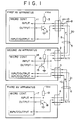
- Fig. 1 is a diagram for illustrating a system to which the present invention is applied.
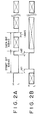
- Figs. 2A and 2B are timing charts of out-going signals from the 10-th pin and 8-th pin of each apparatus shown in Fig. 1, for configuration.
- Fig. 3 is a diagram for illustrating one example of a system comprising a plurality of AV apparatus connected with AV link.
- Fig. 1 is a block diagram for illustrating the system structure to which the present invention is applied. The same numbers are given to the same elements or equivalent elements in Fig. 1 as shown in Fig. 3.
- a control signal wire 20 connects between the 8-th pin (pin-8) of the SCART connector 1 of the first AV apparatus and the 8-th pin (pin-8) of the SCART connector 2 of the second AV apparatus
- a control signal wire 21 connects between the 8-th pin (pin-8) of the SCART connector 3 of the second AV apparatus and the 8-th pin of the SCART connector 4 of the third AV apparatus, in addition to the provision of control signal wires 7 and 9 as in the system shown in Fig. 3.
- the inherent definition of the 8-th pin of a SCART connector is AV signal of "active" at high level and AV signal of "not active” at low level.
- a signal of the 8-th pin is different from a signal of the 10-th pin in that an 8-pin signal is insulated between connectors in an apparatus and operates independently for each connection.
- the second AV apparatus exchanges control signals through the connector 2 between the first AV apparatus, and exchanges control signals through the connector 3 between the third apparatus, characterized in that these exchanges are operated independently. Therefore, the independent operation enables the micro-controller 14 to identify whether the apparatus that transmits a control signal incoming through the 8-th pin is the first AV apparatus or third AV apparatus.
- Fig. 2A represents a signal which the transmission side apparatus outputs from the 10-th pin for configuration
- Fig. 2B represents a signal which the transmission side apparatus outputs from the 8-th pin for configuration.
- the time axis is common for Figs. 2A and 2B.
- an 8.6 msec start bit and subsequent data bits of 4.8 msec each are outputted from the 10-th pin.
- the data bit contains the information for indicating the type of this apparatus (VTR, TV).
- the 8-th pin outputs inherently defined signals, and then the 8-th pin outputs a signal which rises up with a delay of a predetermined period (td1) from the falling edge of the start bit for configuration and tails off itself with a delay of a predetermined period (td2) from the subsequent rising edge of the start bit, thereafter the 8-th pin resumes its function of outputting inherently defined signals.
- the apparatus which receives signals shown in Fig. 2A and Fig. 2B determines that a configuration signal is coming from the 8-th pin if the signal incoming from the 8-th pin rises up with a delay of the above-mentioned predetermined period (td1) from the tailing off of the start bit of the signal inputted from the 10-th pin, and the signal incoming from the 8-th pin tails off with a delay of the above-mentioned predetermined period (td2) from the rising up of the start bit.
- the apparatus which receives a configuration signal can identify the connection to which the signal belongs. Also the apparatus can identify the connector from which the signal incoming currently from the 10-th pin is supplied. The type of apparatus can be identified by examining the data bit subsequent to the start bit supplied from the 10-th pin. Thereby, for example in Fig. 1, the second AV apparatus can identify the type of the first AV apparatus connected to the connector 2 and the type of the third AV apparatus connected to the connector 4. Therefore, configuration of the overall system can be automated.
- the predetermined periods (td1) and (td2) are about 1 ms, however, it is only the important thing that a signal of the 8-th pin is varied with an interposition of a certain time period from the variation of a signal of the 10-th pin, therefore the delay time may be, for example, several tens ms. Two or more pairs of pulses may be outputted.
- each apparatus in a communication system can identify the generator of the signal transmitted from the signal wire connected by way of wired-OR. As a result, automation of the configuration of the whole system can be possible.
Landscapes
- Engineering & Computer Science (AREA)
- Signal Processing (AREA)
- Computer Networks & Wireless Communication (AREA)
- Multimedia (AREA)
- Small-Scale Networks (AREA)
- Communication Control (AREA)
Applications Claiming Priority (2)
| Application Number | Priority Date | Filing Date | Title |
|---|---|---|---|
| JP18002396A JPH1013444A (ja) | 1996-06-20 | 1996-06-20 | 通信システムのコンフィギュレーション方法 |
| JP180023/96 | 1996-06-20 |
Publications (2)
| Publication Number | Publication Date |
|---|---|
| EP0814609A2 true EP0814609A2 (de) | 1997-12-29 |
| EP0814609A3 EP0814609A3 (de) | 1998-12-23 |
Family
ID=16076121
Family Applications (1)
| Application Number | Title | Priority Date | Filing Date |
|---|---|---|---|
| EP97401432A Withdrawn EP0814609A3 (de) | 1996-06-20 | 1997-06-20 | Konfigurationsverfahren eines Kommunikationssystems |
Country Status (2)
| Country | Link |
|---|---|
| EP (1) | EP0814609A3 (de) |
| JP (1) | JPH1013444A (de) |
Cited By (3)
| Publication number | Priority date | Publication date | Assignee | Title |
|---|---|---|---|---|
| EP1317140A3 (de) * | 2001-11-29 | 2004-04-28 | Pace Micro Technology PLC | Funkdatenempfänger mit UART-Zugang |
| EP1406437A3 (de) * | 2002-10-04 | 2004-06-16 | Pace Micro Technology PLC | Rundfunkdatenempfänger |
| EP1367821A3 (de) * | 2002-05-20 | 2005-11-16 | Samsung Electronics Co., Ltd. | Anschliessen von fernsehbezogenen Geräten |
Families Citing this family (1)
| Publication number | Priority date | Publication date | Assignee | Title |
|---|---|---|---|---|
| JP4905098B2 (ja) * | 2006-12-07 | 2012-03-28 | 船井電機株式会社 | 電子機器、ネットワークシステム、及びプログラム |
Family Cites Families (1)
| Publication number | Priority date | Publication date | Assignee | Title |
|---|---|---|---|---|
| NL8602090A (nl) * | 1986-08-18 | 1988-03-16 | Philips Nv | Werkwijze voor het tot stand brengen van een signaalweg tussen ten minste twee apparaten en stelsel van ten minste twee apparaten voor het realiseren van de werkwijze. |
-
1996
- 1996-06-20 JP JP18002396A patent/JPH1013444A/ja not_active Withdrawn
-
1997
- 1997-06-20 EP EP97401432A patent/EP0814609A3/de not_active Withdrawn
Cited By (3)
| Publication number | Priority date | Publication date | Assignee | Title |
|---|---|---|---|---|
| EP1317140A3 (de) * | 2001-11-29 | 2004-04-28 | Pace Micro Technology PLC | Funkdatenempfänger mit UART-Zugang |
| EP1367821A3 (de) * | 2002-05-20 | 2005-11-16 | Samsung Electronics Co., Ltd. | Anschliessen von fernsehbezogenen Geräten |
| EP1406437A3 (de) * | 2002-10-04 | 2004-06-16 | Pace Micro Technology PLC | Rundfunkdatenempfänger |
Also Published As
| Publication number | Publication date |
|---|---|
| JPH1013444A (ja) | 1998-01-16 |
| EP0814609A3 (de) | 1998-12-23 |
Similar Documents
| Publication | Publication Date | Title |
|---|---|---|
| US6865504B2 (en) | Apparatus and method for a reconfigurable pod interface for use with an emulator unit | |
| US5181858A (en) | Cable type identifying and impedance matching arrangement | |
| US5444856A (en) | Apparatus and method for switching ethernet media type | |
| EP0722224A2 (de) | Verfahren zur Aufstellung von Adressen für elektronische Geräte | |
| EP0669727A2 (de) | Verbindung von elektronischen Geräten | |
| EP0588423A2 (de) | Steuerbus für Unterhaltungselekroniksystem mit mehreren Geräten | |
| US3832489A (en) | Bidirectional bus repeater | |
| EP0278430A2 (de) | Steckeranordnung zwischen einer Steuereinrichtung und einer Signalübertragungseinrichtung | |
| US4608562A (en) | Address personalization of a remotely attached device | |
| WO1997016919A3 (en) | Image communications | |
| JPH03500238A (ja) | インタフエースユニツト | |
| US4712210A (en) | Signal conversion circuit for interconnecting coaxial cable and a twisted pair | |
| EP0814609A2 (de) | Konfigurationsverfahren eines Kommunikationssystems | |
| US4885569A (en) | Method and device for transferring signals between modules of an electronic unit | |
| EP0360338A2 (de) | Örtliches Kommunikationsbussystem mit einer Anzahl miteinander verbundener Einrichtungen, einem Steuerbus und einer Anzahl von Signalverbindungen, sowie einer Einrichtung und einem Schaltkasten zur Verwendung in einem derartigen System | |
| EP0032992A1 (de) | Schaltungsanordnung zum Übergang einer mit Halbduplex arbeitenden, digitale Daten übertragenden, Leitung in eine Simplex-Sende- und eine Simplex-Empfangsleitung und umgekehrt | |
| EP0759593A2 (de) | Schnittstelleneinrichtung zwischen einem RS232 Port und einem I2C Bus und Verfahren zu ihrer Verwendung | |
| JP2786010B2 (ja) | 情報コンセントのジャック及び該ジャックを有するホームバスシステム | |
| US5742186A (en) | Asynchronous serial communication channel network | |
| EP0725491A2 (de) | Videosystem zum Verbinden von Kommunikationsgeräten unter Verwendung eines Steuersignals | |
| US4015244A (en) | Selective addressing system | |
| EP0223311A2 (de) | Fernsteuersystem | |
| US5127850A (en) | Method and means for keying signal conductors | |
| KR960009912B1 (ko) | 시리얼 통신장치의 통신회선 확장장치 | |
| WO1999017547A1 (en) | System and apparatus for connecting a number of professional video devices using an atm switch |
Legal Events
| Date | Code | Title | Description |
|---|---|---|---|
| PUAI | Public reference made under article 153(3) epc to a published international application that has entered the european phase |
Free format text: ORIGINAL CODE: 0009012 |
|
| AK | Designated contracting states |
Kind code of ref document: A2 Designated state(s): DE FR GB |
|
| PUAL | Search report despatched |
Free format text: ORIGINAL CODE: 0009013 |
|
| AK | Designated contracting states |
Kind code of ref document: A3 Designated state(s): AT BE CH DE DK ES FI FR GB GR IE IT LI LU MC NL PT SE |
|
| 17P | Request for examination filed |
Effective date: 19990616 |
|
| AKX | Designation fees paid |
Free format text: DE FR GB |
|
| 17Q | First examination report despatched |
Effective date: 20000927 |
|
| GRAH | Despatch of communication of intention to grant a patent |
Free format text: ORIGINAL CODE: EPIDOS IGRA |
|
| STAA | Information on the status of an ep patent application or granted ep patent |
Free format text: STATUS: THE APPLICATION IS DEEMED TO BE WITHDRAWN |
|
| 18D | Application deemed to be withdrawn |
Effective date: 20030102 |