EP0814950B1 - Dispositif et procede de pultrusion - Google Patents
Dispositif et procede de pultrusion Download PDFInfo
- Publication number
- EP0814950B1 EP0814950B1 EP96908720A EP96908720A EP0814950B1 EP 0814950 B1 EP0814950 B1 EP 0814950B1 EP 96908720 A EP96908720 A EP 96908720A EP 96908720 A EP96908720 A EP 96908720A EP 0814950 B1 EP0814950 B1 EP 0814950B1
- Authority
- EP
- European Patent Office
- Prior art keywords
- resin
- fiber
- impregnation vessel
- die
- vessel
- Prior art date
- Legal status (The legal status is an assumption and is not a legal conclusion. Google has not performed a legal analysis and makes no representation as to the accuracy of the status listed.)
- Expired - Lifetime
Links
- 238000000034 method Methods 0.000 title claims description 25
- 230000008569 process Effects 0.000 title claims description 24
- 239000000835 fiber Substances 0.000 claims description 231
- 239000011347 resin Substances 0.000 claims description 224
- 229920005989 resin Polymers 0.000 claims description 222
- 238000005470 impregnation Methods 0.000 claims description 84
- 238000001816 cooling Methods 0.000 claims description 41
- 229920001169 thermoplastic Polymers 0.000 claims description 35
- 239000004416 thermosoftening plastic Substances 0.000 claims description 32
- 238000002844 melting Methods 0.000 claims description 22
- 230000008018 melting Effects 0.000 claims description 22
- 238000010438 heat treatment Methods 0.000 claims description 20
- 230000007246 mechanism Effects 0.000 claims description 14
- 229920005992 thermoplastic resin Polymers 0.000 claims description 8
- 239000007787 solid Substances 0.000 claims description 7
- 239000000463 material Substances 0.000 claims description 6
- 238000005520 cutting process Methods 0.000 claims description 3
- 230000005855 radiation Effects 0.000 claims description 3
- 238000007493 shaping process Methods 0.000 claims description 2
- 230000000694 effects Effects 0.000 claims 2
- 239000012530 fluid Substances 0.000 claims 2
- 238000007654 immersion Methods 0.000 claims 1
- 238000004804 winding Methods 0.000 description 32
- 239000010935 stainless steel Substances 0.000 description 6
- 229910001220 stainless steel Inorganic materials 0.000 description 6
- 239000003638 chemical reducing agent Substances 0.000 description 5
- 230000002787 reinforcement Effects 0.000 description 4
- 229920001187 thermosetting polymer Polymers 0.000 description 4
- YMWUJEATGCHHMB-UHFFFAOYSA-N Dichloromethane Chemical compound ClCCl YMWUJEATGCHHMB-UHFFFAOYSA-N 0.000 description 3
- ZMXDDKWLCZADIW-UHFFFAOYSA-N N,N-Dimethylformamide Chemical compound CN(C)C=O ZMXDDKWLCZADIW-UHFFFAOYSA-N 0.000 description 3
- 239000002904 solvent Substances 0.000 description 3
- HEDRZPFGACZZDS-UHFFFAOYSA-N Chloroform Chemical compound ClC(Cl)Cl HEDRZPFGACZZDS-UHFFFAOYSA-N 0.000 description 2
- PPBRXRYQALVLMV-UHFFFAOYSA-N Styrene Chemical compound C=CC1=CC=CC=C1 PPBRXRYQALVLMV-UHFFFAOYSA-N 0.000 description 2
- 239000011199 continuous fiber reinforced thermoplastic Substances 0.000 description 2
- 239000011152 fibreglass Substances 0.000 description 2
- 239000000383 hazardous chemical Substances 0.000 description 2
- 238000004519 manufacturing process Methods 0.000 description 2
- 230000004048 modification Effects 0.000 description 2
- 238000012986 modification Methods 0.000 description 2
- 230000001473 noxious effect Effects 0.000 description 2
- 239000008188 pellet Substances 0.000 description 2
- -1 polyethylene terephthalate Polymers 0.000 description 2
- 239000000523 sample Substances 0.000 description 2
- 235000014214 soft drink Nutrition 0.000 description 2
- 125000006850 spacer group Chemical group 0.000 description 2
- 238000003860 storage Methods 0.000 description 2
- XLYOFNOQVPJJNP-UHFFFAOYSA-N water Substances O XLYOFNOQVPJJNP-UHFFFAOYSA-N 0.000 description 2
- 238000009736 wetting Methods 0.000 description 2
- YBRVSVVVWCFQMG-UHFFFAOYSA-N 4,4'-diaminodiphenylmethane Chemical compound C1=CC(N)=CC=C1CC1=CC=C(N)C=C1 YBRVSVVVWCFQMG-UHFFFAOYSA-N 0.000 description 1
- 229910000755 6061-T6 aluminium alloy Inorganic materials 0.000 description 1
- 229910000838 Al alloy Inorganic materials 0.000 description 1
- OKTJSMMVPCPJKN-UHFFFAOYSA-N Carbon Chemical compound [C] OKTJSMMVPCPJKN-UHFFFAOYSA-N 0.000 description 1
- SECXISVLQFMRJM-UHFFFAOYSA-N N-Methylpyrrolidone Chemical compound CN1CCCC1=O SECXISVLQFMRJM-UHFFFAOYSA-N 0.000 description 1
- 239000004698 Polyethylene Substances 0.000 description 1
- 229910045601 alloy Inorganic materials 0.000 description 1
- 239000000956 alloy Substances 0.000 description 1
- 239000004760 aramid Substances 0.000 description 1
- 229920006231 aramid fiber Polymers 0.000 description 1
- 244000022782 cocaer Species 0.000 description 1
- 235000008957 cocaer Nutrition 0.000 description 1
- ZPUCINDJVBIVPJ-LJISPDSOSA-N cocaine Chemical compound O([C@H]1C[C@@H]2CC[C@@H](N2C)[C@H]1C(=O)OC)C(=O)C1=CC=CC=C1 ZPUCINDJVBIVPJ-LJISPDSOSA-N 0.000 description 1
- 230000006835 compression Effects 0.000 description 1
- 238000007906 compression Methods 0.000 description 1
- 238000007596 consolidation process Methods 0.000 description 1
- 238000004132 cross linking Methods 0.000 description 1
- 238000009826 distribution Methods 0.000 description 1
- 230000007613 environmental effect Effects 0.000 description 1
- 239000003517 fume Substances 0.000 description 1
- 239000011521 glass Substances 0.000 description 1
- 239000010439 graphite Substances 0.000 description 1
- 229910002804 graphite Inorganic materials 0.000 description 1
- 230000005484 gravity Effects 0.000 description 1
- 239000012943 hotmelt Substances 0.000 description 1
- 239000004615 ingredient Substances 0.000 description 1
- 239000011159 matrix material Substances 0.000 description 1
- 229910052751 metal Inorganic materials 0.000 description 1
- 239000002184 metal Substances 0.000 description 1
- 239000000203 mixture Substances 0.000 description 1
- 239000000178 monomer Substances 0.000 description 1
- 238000013021 overheating Methods 0.000 description 1
- 239000004033 plastic Substances 0.000 description 1
- 229920003023 plastic Polymers 0.000 description 1
- 229920000573 polyethylene Polymers 0.000 description 1
- 229920000139 polyethylene terephthalate Polymers 0.000 description 1
- 239000005020 polyethylene terephthalate Substances 0.000 description 1
- 238000006116 polymerization reaction Methods 0.000 description 1
- 239000000843 powder Substances 0.000 description 1
- 238000001556 precipitation Methods 0.000 description 1
- 239000000376 reactant Substances 0.000 description 1
- 235000021572 root beer Nutrition 0.000 description 1
- 229920006395 saturated elastomer Polymers 0.000 description 1
- 238000000926 separation method Methods 0.000 description 1
- 239000002002 slurry Substances 0.000 description 1
- 230000007704 transition Effects 0.000 description 1
- 239000011800 void material Substances 0.000 description 1
Images



Classifications
-
- B—PERFORMING OPERATIONS; TRANSPORTING
- B29—WORKING OF PLASTICS; WORKING OF SUBSTANCES IN A PLASTIC STATE IN GENERAL
- B29C—SHAPING OR JOINING OF PLASTICS; SHAPING OF MATERIAL IN A PLASTIC STATE, NOT OTHERWISE PROVIDED FOR; AFTER-TREATMENT OF THE SHAPED PRODUCTS, e.g. REPAIRING
- B29C70/00—Shaping composites, i.e. plastics material comprising reinforcements, fillers or preformed parts, e.g. inserts
- B29C70/04—Shaping composites, i.e. plastics material comprising reinforcements, fillers or preformed parts, e.g. inserts comprising reinforcements only, e.g. self-reinforcing plastics
- B29C70/28—Shaping operations therefor
- B29C70/40—Shaping or impregnating by compression not applied
- B29C70/50—Shaping or impregnating by compression not applied for producing articles of indefinite length, e.g. prepregs, sheet moulding compounds [SMC] or cross moulding compounds [XMC]
- B29C70/52—Pultrusion, i.e. forming and compressing by continuously pulling through a die
- B29C70/521—Pultrusion, i.e. forming and compressing by continuously pulling through a die and impregnating the reinforcement before the die
-
- B—PERFORMING OPERATIONS; TRANSPORTING
- B29—WORKING OF PLASTICS; WORKING OF SUBSTANCES IN A PLASTIC STATE IN GENERAL
- B29B—PREPARATION OR PRETREATMENT OF THE MATERIAL TO BE SHAPED; MAKING GRANULES OR PREFORMS; RECOVERY OF PLASTICS OR OTHER CONSTITUENTS OF WASTE MATERIAL CONTAINING PLASTICS
- B29B15/00—Pretreatment of the material to be shaped, not covered by groups B29B7/00 - B29B13/00
- B29B15/08—Pretreatment of the material to be shaped, not covered by groups B29B7/00 - B29B13/00 of reinforcements or fillers
- B29B15/10—Coating or impregnating independently of the moulding or shaping step
- B29B15/12—Coating or impregnating independently of the moulding or shaping step of reinforcements of indefinite length
- B29B15/122—Coating or impregnating independently of the moulding or shaping step of reinforcements of indefinite length with a matrix in liquid form, e.g. as melt, solution or latex
-
- B—PERFORMING OPERATIONS; TRANSPORTING
- B29—WORKING OF PLASTICS; WORKING OF SUBSTANCES IN A PLASTIC STATE IN GENERAL
- B29K—INDEXING SCHEME ASSOCIATED WITH SUBCLASSES B29B, B29C OR B29D, RELATING TO MOULDING MATERIALS OR TO MATERIALS FOR MOULDS, REINFORCEMENTS, FILLERS OR PREFORMED PARTS, e.g. INSERTS
- B29K2067/00—Use of polyesters or derivatives thereof, as moulding material
- B29K2067/003—PET, i.e. poylethylene terephthalate
-
- B—PERFORMING OPERATIONS; TRANSPORTING
- B29—WORKING OF PLASTICS; WORKING OF SUBSTANCES IN A PLASTIC STATE IN GENERAL
- B29K—INDEXING SCHEME ASSOCIATED WITH SUBCLASSES B29B, B29C OR B29D, RELATING TO MOULDING MATERIALS OR TO MATERIALS FOR MOULDS, REINFORCEMENTS, FILLERS OR PREFORMED PARTS, e.g. INSERTS
- B29K2101/00—Use of unspecified macromolecular compounds as moulding material
- B29K2101/12—Thermoplastic materials
Definitions
- This invention relates generally to the manufacture of fiber reinforced structures and relates specifically to an improved pultrusion apparatus and process for making resin impregnated fibers in the form of rods, bars, tubes, pipes, and other structural shapes.
- the invention relates to a pultrusion system according to the pre-characterizing portion of claim 1 and to a process of making thermoplastic impregnated fibers.
- a generic pultrusion system according to the pre-characterizing portion of claim 1 is known from US 5,225,020.
- Pultrusion is the term used to describe continuous pulling of fiber tows or rovings through a resin for impregnation, through a heated die for polymerization, and to a cut-off station for cutting the pultruded structure to desired lengths.
- Pultrusion processes using reinforcements of fiberglass, graphite, and aramid fibers, and thermosetting resins, are well known, and are commonly referred to as “conventional pultrusion", while pultrusion processes using thermoplastic resins are very rare.
- thermosetting resin pultrusion acquired structures One disadvantage of thermosetting resin pultrusion acquired structures is the inability to reform or reshape a structure after it has passed through the process, due to the inability to reverse the cross-linking of the resin molecules in the process.
- thermosetting resin use in pultrusion is the necessity of noxious and hazardous chemicals and solvents employed in the process ingredients. These materials include monomers and reactants such as styrene and methylenedianiline, and others.
- thermoplastic pultrusion such as methylene chloride, chloroform, dimethyl formamide, and normal methyl pyrrolidone, employed in dissolving thermoplastic polymers prior to impregnating fibers in slurries and solutions, also present problems.
- thermoplastic pultrusion methodology Another disadvantage of presently used thermoplastic pultrusion methodology is the inability to achieve an optimum fiber to resin volume ratio, and thereby maximize mechanical strength, specifically compression, flexural, and tensile strengths in the pultruded structure.
- thermoplastic pultrusion products and processes are the inability to thoroughly wet-out fibers, thereby causing voids in resin starved areas; the cost of using prefabricated tow preg or prepreg tapes; and the limit to available lengths of these materials since they are generally manufactured by venders outside of the pultrusion industry and not available in lengths customarily employed by the pultrusion industry.
- thermoplastic impregnated fibers according to claim 22.
- the system and the process according to the invention allow to provide thermoplastic structural profiles or shapes that are essentially void free, and can be reshaped or post fabricated into additional shapes and structures by applying heat and pressure. Furthermore the system and the process according to the invention can employ, either recycled thermoplastic, such as polyethylene terephthalate from recycled plastic soft drink bottles, or unused or virgin resins.
- recycled thermoplastic such as polyethylene terephthalate from recycled plastic soft drink bottles, or unused or virgin resins.
- the system and the process according to the invention are environmental friendly and operate without solvents or hazardous chemicals. They generate no noxious fumes. Moreover they are cost effective and can be used to produce continuous long length fiber reinforced thermoplastic structures that may be cut to the desired lengths or stored on or transported on spools.
- fiber reinforced thermoplastic structures may be fabricated into tension cables for bridges, retaining walls, and reinforcement bars in concrete and suitable for use in corrosive environments and earthquake sensitive areas.
- multiple tows of fiber can be impregnated in a hot-melt thermoplastic pultrusion process that insures through resin wetting and impregnation while maintaining a uniform resin flow and eliminating overheating and charring of the resin.
- Pultrusion machine 10 is employed to make continuous lengths of useful structural materials from suitable continuous fiber tows or rovings and heat processible thermoplastic polymers or resins.
- Multiple spools 11 of suitable fiber tows 12 are provided with the ends of the individual fiber tows 12, leading from spools 11, being threaded through a fiber tow guide and heating vessel 13 into an impregnation vessel 14 attached thereto.
- Impregnation vessel 14 is filled with molten impregnation material 15 received from a resin melting vessel 16 through a filter 17 at entrance port 18. Unmelted resin enters melting vessel 16 through feed tube 19, as will be explained further hereinafter.
- Impregnation vessel 14 is provided with a fiber entrance end 20 that maintains separation of fiber tows 12 passing therethrough.
- a fiber control insert 21 is attached to fiber entrance end 20 and a resin flow control insert 22 suspended horizontally within or inside of fiber control insert 21.
- a fiber exit end 23 is provided in impregnation vessel 14, the structure of which will be further explained hereinafter.
- a resin meter and profile die 30 is attached to exit end 23 of impregnation vessel 14 and a cooling die 32 is attached at the exit end of resin meter and profile die 30, the structure of which will also be further explained hereinafter.
- Fiber tows 12, maintained separated, are impregnated with molten resin 15 while passing through impregnation vessel 14, and one or a plurality of fiber tows 12 impregnated with resin 15 are directed into a single or plurality of passageways provided by resin meter and profile die 30 and cooling die 32, as will be explained further hereinafter.
- Fiber tows 12, impregnated with resin 15, are consolidated and cooled below the melting temperature of resin 15 to form fiber reinforced thermoplastic structure 33.
- the fiber reinforced structure 33 is continuously pulled by pulling mechanism 34 through cut-off station 36 and cut to the desired lengths 33a.
- Pulling mechanism 34 comprises a pair of spaced motor driven belts (not designated) for frictionally contacting and pulling fiber reinforced structure therethrough.
- fiber reinforced thermoplastic structure 33 may be pulled and coiled on a spool by a pulling and winding device, as will be further explained hereinafter.
- fiber tow guide and heating vessel 13 is provided with an entrance end plate 53 having a plurality of separated tow passageways or openings 54 therethrough, arranged in a circular pattern, for threadingly receiving separate fiber tows 12 from spools 11.
- a circular threading pattern is employed in order to introduce fiber tows 12 into impregnation vessel 14 through entrance end 20 ready for distribution evenly around fiber control insert 21.
- Entrance end plate 53 is attached to entrance end bracket 55, and is detachable and replaceable to accommodate any number of tows or rovings and diverse filament counts or yields.
- Entrance end bracket 55 is also detachable from the fiber heating section 56 of fiber tow guide and heating vessel 13.
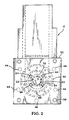
- Fiber heating section 56 of fiber tow guide and heating vessel 13 is cylindrical in configuration, as illustrated in FIGS 2 and 3.
- Fiber tow guide and heating vessel 13 is provided with attachment flange 57 and secured to impregnation vessel 14 by screws or bolts 58 extending through flange 57.
- the screws or bolts 58 are threaded into fiber entrance end 20 of impregnation vessel 14.
- Fiber entrance end 20 of impregnation vessel 14 extends inside fiber guide and heating vessel 13 a short distance (0.75 inch in a specific embodiment) to thereby supply heat, by radiation, inside fiber guide and heating vessel 13 for preheating fiber tows 12 prior to entering impregnation vessel 14 through fiber entrance end 20.
- entrance plate 53, fiber preheating section 56, and flange 57 of fiber tow guide and heating vessel 13 were fabricated from type 347 stainless steel and polished to a surface finish of 0.1016 ⁇ m (four micro-inches) root mean square (RMS). Entrance end bracket 55 was fabricated from type 6061-T3 aluminum alloy.
- Impregnation vessel 14 is provided with a cylindrical interior, filled with molten resin 15 which enters through entrance port 18, and provided with detachable fiber entrance end 20, fiber control insert 21, resin flow control insert 22, and detachable exit end 23.
- a resin meter and profile die 30 is attached to the exterior of exit end 23.
- Fiber tows 12 are separated and directed into impregnation vessel 14 through individual passageways 63 (FIGS 2, 3, and 7) which are equally spaced in a circular pattern, having center axis in line with center axis of impregnation vessel 14.
- the inside end of passageways 63 intersect the hemispherical or concave interior surface of fiber entrance end 20.
- fiber control insert 21 is attached to the interior surface of fiber entrance end 20, secured by four screws or bolts 64 and spacers 65, and suspended horizontally and longitudinally in the center of impregnation vessel 14.
- Fiber control insert 21 is provided with four fiber guide rings, designated 42, 43, 44, and 45, and secured to each other by eight horizontally inserted fiber guide rods 26 which are employed to maintain adjustable spacing between fiber guide rings 42,43,44,45 and to guide and maintain separated equal spacing between individual fiber tows 12 throughout the impregnation process.
- Fiber guide rings 42, 43, 44 and 45 are cylindrical rings, having rectangular cross-sections, and each have an outside or periphery and an inside opening or passageway.
- Fiber guide rings 42,43, 44, and 45 All sharp edges on fiber guide rings 42,43, 44, and 45 are removed and edges are provided with 1.57 mm (0.062 inch)radiuses and polished to a surface finish of 0.1016 ⁇ m (four micro-inches) RMS.
- Fiber guide rings 42 and 44 have circumferential grooved areas 66 and 67, respectively, in their outside surfaces to provide passageways for resin to flow under fiber tows 12.
- Fiber tows 12 are directed to pass over the outside or periphery of fiber guide ring 42 and forced to open and spread, which increases tension on, and removes twists in, fiber tows 12. While fiber tows 12 are passing over the outside or periphery of fiber guide ring 42, grooved area 66 in the periphery of fiber guide ring 42 provides for melted resin 15 flow to the underside of the opened and spread fiber tows 12, infiltrating and impregnating fiber tows 12, and flowing around filaments within spread fiber tows 12 while simultaneously, resin 15 is infiltrating and impregnating from the outside of spread fiber tows 12.
- Fiber tows 12, spread opened and impregnated with molten resin 15, are directed between guide rods 26 to the inside perimeter of fiber guide ring 43 and forced to close. This increases tension on fiber tows 12, causing filaments and absorbed molten resin 15 to consolidate, squeezing out excess resin 15 and forcing filaments within fiber tows 12 to thoroughly wet-out. Further, fiber tows 12 are directed to pass over the outside periphery of fiber guide ring 44 and forced to again open and spread a second time, which further increases tension on fiber tows 12, and removes any remaining twists in fiber tows 12.
- grooved area 67 in the periphery of fiber guide ring 44 provides for resin 15 to flow into the underside of opened and spread fiber tows 12, infiltrating and impregnating fiber tows 12, and flowing around filaments within spread fiber tows 12 while, simultaneously, resin 15 is infiltrating and impregnating from the outside of spread fiber tows 12.
- Fiber tows 12, spread open and saturated with impregnating resin 15, are directed to the inside perimeter of fiber guide ring 45 and forced to close a second time, which increases tension on fiber tows 12, causing consolidation of filaments and absorbed resin 15, squeezing out excess resin 15 and forcing filaments within fiber tows 12 to thoroughly wet-out, thereby perfecting fiber wetting and impregnation in fiber tows 12.
- Resin flow control insert 22 is an elongated round bar, having a flat end 68, with sharp edges removed, and a second end 69 hemispherical in shape, suspended and secured horizontally through the center of fiber control rings 42 and 44 by five retaining and centering bolts 71. These five bolts 71 extend through suitable recessed threaded holes in each of fiber control rings 42 and 44 to engage respective holes in resin flow control insert 22 for positioning thereof, as illustrated in FIGS 2, 6 and 7.
- Resin flow control insert 22 controls the volume and flow of melted resin 15 in impregnation vessel 14 by eliminating space where resin 15 is not required and forcing resin 15 to flow in the path or course of fiber tows 12 as the fiber tows move through impregnation vessel 14.
- a space 70 maintained between resin flow control insert 22 and the inside perimeter of fiber control insert 21 (FIGS 2, 6 and 7), forces resin 15 to flow between and around fiber tows 12 and fiber control rings 42, 43, 44, and 45.
- the hemispherical end 69 of resin flow control insert 22 extends into the concave interior side of fiber entrance end 20, forcing resin 15 to flow between fiber tows 12 as the fiber tows begin to spread open while moving toward the periphery or outside of fiber control ring 42.
- Impregnation vessel 14 is heated by a plurality of electrical cartridge heaters 48 inserted in passageways 48a machined horizontally in exterior wall of sides and bottom of impregnation vessel 14, as shown in FIGS 2, 3 and 6.
- Impregnation vessel 14 fiber and resin exit end 23 and fiber entrance end 20 are preferably fabricated from type 347 stainless steel stock and their inside surfaces, including inside surfaces of fiber entrance passageways, are polished to a surface finish of 0.1016 ⁇ m (four micro-inches) RMS.
- Fiber control insert 21 and resin control insert 22 are preferably fabricated from type 17-4 precipitation hardened (PH) stainless steel, heat treated to Rockwell C-45, and polished to a surface finish of 0.1016 ⁇ m (four micro-inches) RMS.
- Feed tube 19 and resin melting vessel 16 are cylindrical tubes, attached to the top side of impregnation vessel 14, and detachable from each other at joint 60. Resin melting vessel 16 is detachable from impregnation vessel 14 at joint 62. Resin melting vessel 16 is heated by band heater 61. Solid unmelted thermoplastic polymer or resin 15, or a combination of two or more mixed resins (blend), in physical forms such as pellets, powder, chips, chunks or shreds, is transferred to feed tube 19. The solid resin flows under the influence of gravity into resin melt vessel 16 and is heated to slightly above its melting temperature while passing through resin melting vessel 16.
- Resin feed tube 19 and resin melting vessel 16 can be of any reasonable height and diameter, and a continuous resin replenishing device can, obviously, be attached to resin feed tube 19 if needed, or so desired.
- a filter screen 17 is attached to the exit end, or bottom 18, of resin melting vessel 16, which filters, or removes, unmelted debris and allows only melted resin 15 to pass through and flow into impregnation vessel 14.
- Filter screen 17 is fabricated from type 347 stainless steel, perforated with holes, 2,36 mm (0.093 inch) in diameter, and polished to a surface finish of 0.1016 ⁇ m (four micro-inches) RMS.
- Feed tube 19 and resin melting vessel 16 are fabricated from type 347 stainless steel and their inside surfaces are polished to a surface finish of 0.1016 ⁇ m (four micro-inches) RMS, which essentially eliminates friction between metal surfaces and melted resin 15 as the resin flows through resin melting vessel 16 and filter 17, into entrance port 18 in impregnation vessel 14.
- resin meter and profile die 30 is provided with one or a plurality of through passageways 72 having varied size cross-sections, 73, 74, 75 and 76, disposed in reducing size relationship at strategic locations, to meter off excess resin and consolidate fiber tows 12 and the impregnated resin 15.
- Resin meter and profile die 30 is provided with an entrance end 77, exit end 78, attachment flange 79, attachment bolts 80, heat shield flange 82 with threaded bolt holes 83 receiving bolts 84 for attachment of cooling die 32 via cooling die flange 82a.
- a plurality of cartridge heaters 81 are disposed in suitable holes (not designated) machined in combined resin meter and profile die 30, and a heat control thermocouple probe 81a is disposed in a single hole machined in the side thereof.
- Cooling die 32 is provided with a through passageway 85, having a constant cross-section identical in size and shape to passageway 76 in resin meter and profile die 30, an entrance end adjacent and aligned with exit end 78 of resin meter and profile die 30, and an exit end 86.
- Passageways 87 in cooling die 32 are provided for chilled water circulation for cooling the resin in pultruded thermoplastic structure 33, and a temperature control thermocouple probe 88 is provided in a suitable machined hole therein.
- Resin meter and profile die 30 is secured to impregnation vessel 14 by bolts 80 threaded into exit end 23 of impregnation vessel 14 through flange 79.
- Resin meter and profile die 30 in the specific embodiment illustrated in FIG 3 is for the fabrication of impregnated solid rod reinforcement structures but is detachable and interchangeable with other resin meter and profile dies designed to produce other sizes and shapes, such as square, rectangular, angular, channel, pipe, tube, I-beam, and the like.
- fiber tows 12, either one or a plurality, impregnated with resin 15 are pulled into entrance end 77 of resin meter and profile die 30. While passing through cross-section 73 of passageway 72, a volume of resin 15 is metered off, or debulked, to 1.7 times the volume of resin 15 required in pultruded fiber reinforced structure 33, and resin 15 and fiber tows 12 are compacted. While passing through cross-section area 74, resin 15 is further metered off, leaving 1.5 times the volume of resin 15 required in pultruded fiber reinforced thermoplastic structure 33, and further compacted.
- resin 15 When passing through cross-section area 75 resin 15 is further metered off to 1.4 times the volume of resin required in pultruded fiber reinforced thermoplastic structure 33 and further compacted, and when passing through profile and shaping section 76, resin 15 is metered off to the final volume of resin required in structure 33. Fiber tows 12 and resin 15 are consolidated forming pultruded fiber reinforced thermoplastic structure 33, which is then cooled to below the melting temperature of matrix resin 15 while passing through passage 85 of cooling die 32.
- the fiber volume percent and resin volume percent required in pultruded thermoplastic structure 33 is preselected or predetermined; and resin meter and profile die 30 and cooling die 32 are constructed to achieve the predetermined or selected volume ratios.
- Fiber reinforced thermoplastic structure 33 is pulled by a belted pulling mechanism 34 (FIG 1) through cut-off station 36, or pulled by a pulling and winding device, as will be explained hereinafter in reference to the embodiment of the invention shown in FIG 5.
- FIG 4 details of a system according to the present invention for obtaining pultruded fiber reinforced thermoplastic pipe or tube, either round, square, rectangular of other open center profiles is illustrated.
- an elongated sting or mandrel 89 is secured to and extends from flow control insert 22.
- Sting 89 is fabricated from round rod or bar stock having an outside diameter or dimension equal to the inside diameter of the fiber reinforced thermoplastic tube 90 to be pultruded.
- Sting 89 is extended horizontally through the center of resin meter and profile die 30 and cooling die 32.
- Sting 89 is attached to flat end 68 of resin flow control insert 22 and extends through passageway 72 of resin meter and profile die 30 and passageway 85 of cooling die 32.
- a space 91 is maintained between sting 89 and the inside wall of profile forming section 76 of resin meter and profile die 30.
- tows 12 are distributed around sting 89 and pulled through impregnation vessel 14 for impregnation with resin 15, as previously described.
- Excess impregnating resin 15 is metered out of fiber tows 12 as the resin impregnated tows pass through cross-section areas 73, 74, 75 and 76, leaving only the volume of resin 15 required to achieve the desired final fiber tows 12 volume to resin 15 volume ratio in the fiber reinforced thermoplastic tube 90.
- Fiber reinforced thermoplastic tube 90 is pulled by pulling mechanism 34 (FIG 1) to cut-off station 36, and cut to the desired lengths 36a.
- resin meter and profile die 30 and sting 89 are fabricated from 17-4 PH stainless steel, and heat treated to Rockwell C-45 hardness, and cooling die 32 fabricated from 6061-T6 aluminum alloy. Through passageways 72 and 85 of resin meter and profile die 30 and cooling die 32, respectively, and entrance ends and exit ends of resin meter and profile die 30 and cooling die 32 are polished to a surface finish of 0.1016 ⁇ m (four micro-inches) RMS.
- an additional modification of the present invention employs a pulling and winding spool, generally designated by reference numeral 93, to exert the pulling force needed in pultrusion system 10 and to serve as storage device for separate continuous fiber reinforced structures produced according to the present invention.
- the fiber structures 133 in this specific embodiment were round rods, each having a diameter of 2.87 mm (0.113 inch).
- the fiber reinforcement (fiber tows 12) was fiberglass roving, 103.33m per 453.59g (113 yards per pound) yield, electrical grade (E-glass).
- Two separate batches of resin 15 were used, with one batch consisting of polyethylene terephtahlate (PET), which was reclaimed from two and three liter soft drink bottles. The bottles were mixed, some clear, some green in color, and originally used to bottle Coca ColaTM, Pepsi ColaTM, 7-UpTM, SpriteTM, Mountain DewTM, root beer, etc.
- the recycled bottles were chopped into chips, chunks, and shreds for feeding into feed tube 19 (FIG 1).
- a second batch of resin 15, consisted of virgin or unused bottle grade PET, and supplied in pellets by a commercial supplier. Both the recycled PET bottles and the unused PET performed excellent and produced structural quality fiber reinforced rods.
- Combined resin meter and profile die 30a with cooling die 32a attached to resin meter and profile die 30a is attached to exit end 23 of impregnation vessel 14.
- Combined resin meter and profile die 30a and cooling die 32a are provided with a plurality of five separated through passageways, designated by reference numerals 126, 127, 128, 129 and 130.
- Two roving ends are threaded through each of the five passageways, 126, 127, 128, 129 and 130 which are machined to pre-calculated dimensions To achieve a fiber volume of fifty-five percent and a resin volume of forty-five percent in structures 133, as will be further explained hereinafter.
- the ends of the rovings exiting from passageways 126, 127, 128, 129 and 130 respectively, are threaded through guides 131 and 132 and attached to pulling and winding spool mechanism 93, in respective compartments 134,135,136, 137 and 138, as will also be further explained hereinafter.
- impregnation vessel heaters 48 inserted in cavities 48a in vessel 14, combined resin meter and profile die heaters 81, resin melting vessel heater 61, and chilled water circulation in cooling die 32a, are all activated. Unmelted thermoplastic resin 15 is transferred to feed tube 19 and, when operating temperature is reached, the melted thermoplastic resin 15 in melting vessel 16 flows into impregnation vessel 14 and is continuously replenished through feed tube 19. Pulling and winding spool mechanism 93 is activated to commence pulling and winding.
- the ratio of resin volume to fiber volume allowed to pass through resin meter area 73 is seventy-eight volume percent resin 15 and twenty-two volume percent fiber tows 12.
- the ratio of resin to fiber allowed to pass through resin meter 74 is seventy volume percent resin 15 to thirty volume percent fiber tows 12; and, while passing through resin meter area 75, the resin to fiber ratio is reduced to sixty-four volume percent resin to thirty-six volume percent fiber tows 12.
- the final excess resin 15 is metered out of fiber tows 12, resulting in a resin to fiber ratio of forty-five volume percent resin to fifty-five volume percent fiber tows 12, which is the ratios for which resin meter and profile die 30a is designed to achieve.
- fiber tows 12 and resin 15 While passing through area 76 of passageways 126, 127, 128, 129 and 130, fiber tows 12 and resin 15 are consolidated to form fiber reinforced thermoplastic structures 133, and in passing through cooling die 31, the temperature of structures 133 is lowered to below the melting point of resin 15, causing the resin to solidify.
- Structures 133, exiting from cooling die 32a are pulled through separated stationary guides 131.
- Stationary guides 131 are fixed to the frame of pulling and winding spool mechanism 93 to provide for alignment and leveling of structures 133 with resin meter and profile die 30a and cooling die 32a, and for transition through winding guides 132, which are mounted on winding arm 152.
- Winding arm 152 is fixedly attached to pulling and winding spool 93, as will be further explained hereinafter.
- Structures 133 are pulled through winding guides 132 and wound in separated compartments 134, 135, 136, 137 and 138, respectively, on spool body 95 which is attached to pulling and winding spool 93.
- Pulling and winding spool 93 is a mechanized device or machine, designed for pulling and winding small diameter rods or thin flat rectangular bars on a spool body and is provided with winding guide 132; detachable winding spool body 95 with compartments 134, 135, 136, 137 and 138; drive shaft 139; drive clutch 140; sprockets 141, 142, 145, and 147; drive chains 144 and 146; drive motor 143; speed reducer 148; a drive arm 149; drive link 151; connecting pins 97 and 98; winding arm 152; winding arm bearings 99; drive shaft bearings 96; and frame 100.
- drive motor 143 supplies power to drive sprocket 142.
- Drive sprocket 142 drives sprocket 141 through drive chain 144, clutch 140 attached to drive shaft 139 mounted to frame 100 by bearings 96, engages sprocket 141, which causes drive shaft 139 to rotate.
- Spool body 95 is attached to drive shaft 139 and rotates when clutch 140 is engaged with sprocket 141, and sprocket 141 is rotating.
- Spool body 95 is provided with separated compartments 134, 135, 136, 137 and 138, in which structures 133 are wound.
- Sprocket 145 is attached to drive shaft 139 and caused to rotate when clutch 140 is engaged, and drive shaft 139 and spool body 95 are rotating.
- Sprocket 145 drives sprocket 147 through drive chain 146.
- Sprocket 147 is connected to right angle speed reducer 148, which is mounted to frame 100 and, when rotating, causes drive shaft 150 of speed reducer 148 to rotate.
- One end of drive arm 149 is attached to drive shaft 150, a second end of drive arm 149 is attached to one end of drive link 151 by pin 97.
- a second end of driver link 151 is attached to winding arm 152 by pin 98.
- Winding arm 152 is mounted to frame 100 by linear bearings 99.
- Speed reducer 148 is designed to rotate drive arm 149 in a counter clockwise direction, and when moving through the 9:00 O'clock position, winding arm 152 position is at the maximum left location, as viewed from cooling die 32a.
- drive arm 149 moves past the 9:00 O'clock position (toward 6:00 O'clock position)
- winding arm 152 reverses direction and begins to move to the right
- winding arm 152 reverses direction again and starts to move to the left.
- structures 133 are wound in layers, as winding arm 152 moves left and right, reversing directions each time drive arm 149 rotates 180 degrees.
- Speed reducer 148 causes drive arm 149, through drive link 151, to move winding arm 152 a distance equal to the diameter or width of structures 33 with each revolution of spool body 95.
- Structures 133, constrained by winding guides 132, are gradually moved a distance equal to their respective diameters or widths with each revolution of spool body 95 as the spool winds structures 133 into separated individual compartments 134, 135, 136, 137 and 138.
Landscapes
- Engineering & Computer Science (AREA)
- Mechanical Engineering (AREA)
- Chemical & Material Sciences (AREA)
- Composite Materials (AREA)
- Moulding By Coating Moulds (AREA)
Claims (25)
- Système de pultrusion (10) pour fabriquer des structures renforcées de longueur continue (33), comprenant :caractérisé par :une cuve d'imprégnation de résine (14) pour contenir une quantité d'une résine d'imprégnation (15) et ayant une extrémité d'entrée de fibres et une extrémité de sortie de fibres,des moyens fournissant une alimentation continue d'une résine d'imprégnation (15) à ladite cuve d'imprégnation de résine (14),une pluralité de bobines (11) de câble de fibres (12) placées à proximité de ladite cuve d'imprégnation (14)un dispositif de contrôle d'écoulement de résiné (22) servant à diriger l'écoulement de résine vers les câbles de fibres (12) et l'extrémité de sortie de ladite cuve d'imprégnation (14),une filière à profiler (30, 30a) fixée à ladite extrémité de sortie de la cuve d'imprégnation (14) pour recevoir les câbles de fibres imprégnées et former le profilé définitif de la structure pultrudée (33), etun mécanisme de tirage (93) pour tirer les câbles de fibres imprégnées,une cuve de guidage et de chauffage de fibres (13) placée entre ladite pluralité de bobines (11) de câble de fibres (12) et ladite cuve d'imprégnation (14),une plaque d'extrémité dans ladite cuve de guidage et de chauffage de fibres (13) et équipée d'une série d'ouvertures disposées dans une configuration circulaire,ladite cuve de guidage et de chauffage de fibres (13) étant fixée à ladite cuve d'imprégnation (14) et servant à guider et à maintenir séparées à travers ladite plaque d'extrémité, les câbles de fibres individuels (12) partant ladite pluralité de bobines (11) et guidant lesdits câbles dans ladite cuve d'imprégnation (14),des moyens (56) fournissant une chaleur rayonnante à ladite cuve de guidage et de chauffage de fibres (13) pour préchauffer les câbles de fibres (12) passant à travers la cuve d'imprégnation (14),des moyens prévus dans ladite extrémité d'entrée des fibres de ladite cuve d'imprégnation (14) servant à maintenir les câbles de fibres individuels (12) séparés et dans une configuration circulaire aboutissant à ladite cuve d'imprégnation (14),un élément de contrôle de fibres (21) placé à l'intérieur de ladite cuve d'imprégnation (14) et comprenant une série de bagues cylindriques espacées,des moyens de suspension horizontale dudit élément de contrôle de fibres (21) à l'intérieur de ladite cuve d'imprégnation (14),un appareil de mesure de résine combiné à la filière à profiler (30, 30a) pour contrôler la quantité de résine d'imprégnation (15) contenue dans les câbles de fibres à la sortie, etune filière de refroidissement (32, 32a) fixée audit appareil de mesure de résine-filière à profiler combiné (30, 30a) et servant à abaisser la température des câbles de fibres imprégnées en sortie dudit appareil de mesure de résine-filière à profiler combiné (30, 30a) à une température inférieure au point de fusion de la résine d'imprégnation (15),dans lequel ledit dispositif de contrôle d'écoulement de résine (22) est suspendu horizontalement à travers le centre dudit élément de contrôle de fibres (21),dans lequel ledit mécanisme de tirage (93) tire les câbles de fibres imprégnées de ladite filière de refroidissement (32, 32a), etdans lequel ladite résine (15) est une résine thermoplastique.
- Système de pultrusion (10) selon la revendication 1, caractérisé en ce que lesdits moyens fournissant une alimentation continue d'une résine d'imprégnation comprennent :un tube d'alimentation de résine (19) ayant une première extrémité pour recevoir une alimentation en matériau de résine solide, une deuxième extrémité en communication fluide avec ladite cuve d'imprégnation de résine (14), une partie intermédiaire placée entre lesdites première et deuxième extrémités, etdes moyens chauffants placés à proximité de ladite partie intermédiaire pour fondre le matériau de résine solide avant qu'il ne soit reçu par ladite cuve d'imprégnation de résine (14).
- Système de pultrusion (10) selon la revendication 2, caractérisé en ce qu'il comprend un élément filtrant (17) placé dans ledit tube d'alimentation de résine (19) entre ladite partie intermédiaire et ladite deuxième extrémité dudit tube d'alimentation de résine (19) en communication fluide avec ladite cuve d'imprégnation de résine (14), lesdits moyens chauffants convertissant ladite résine solide en une masse de résine fondue (15) et ledit élément filtrant (17) servant à empêcher toute résine solide de pénétrer dans ladite cuve d'imprégnation de résine (14).
- Système de pultrusion (10) selon la revendication 3, caractérisé en ce que lesdits moyens de chauffage comprennent un réchauffeur à bande (61) encerclant ladite partie intermédiaire dudit tube d'alimentation de résine (19).
- Système de pultrusion (10) selon la revendication 3, caractérisé en ce que ladite cuve d'imprégnation de résine (14) est équipée d'une structure d'extrémité d'entrée plane ayant un premier côté s'étendant à l'intérieur de ladite cuve de guidage et de chauffage de fibres (13) et un deuxième côté présentant une ouverture concave et dans laquelle la chaleur de ladite masse de résine fondue (15) reçue par ladite cuve d'imprégnation de résine (14) en combinaison avec la chaleur fournie à ladite cuve d'imprégnation de résine (14) sert à fournir de la chaleur rayonnante à ladite cuve de guidage et de chauffage de fibres (13) à travers ladite structure d'extrémité plane.
- Système de pultrusion (10) selon la revendication 5, caractérisé en ce que lesdites bagues cylindriques espacées sont interconnectées et en ce que lesdits moyens suspendant horizontalement ledit élément de contrôle de fibres (21) à l'intérieur de ladite cuve d'imprégnation (14) comprennent une pluralité de vis espacées (64) traversant ladite structure d'extrémité d'entrée plane et reçues par au moins une desdites séries de bagues cylindriques espacées.
- Système de pultrusion (10) selon la revendication 1, caractérisé en ce qu'il comprend une pluralité de vis espacées connectant au moins une desdites séries de bagues cylindriques espacées audit dispositif de contrôle d'écoulement de résine (22) pour maintenir ledit dispositif de contrôle d'écoulement de résine (22) suspendu horizontalement à travers le centre dudit élément de contrôle de fibres (21).
- Système de pultrusion (10) selon la revendication 7, caractérisé en ce que ladite pluralité de vis espacées connectant au moins une desdites séries de bagues cylindriques espacées audit dispositif de contrôle d'écoulement de résine (22) comprend cinq vis uniformément espacées traversant transversalement lesdites au moins une desdites séries de bagues cylindriques espacées et introduites par vissage dans la surface extérieure dudit dispositif de contrôle d'écoulement de résine (22).
- Système de pultrusion (10) selon la revendication 1, caractérisé en ce que ladite cuve d'imprégnation de résine (14) est équipée d'une structure d'extrémité d'entrée plane traversée par une ouverture concave et ledit dispositif de contrôle d'écoulement de résine (22) est équipé d'une première extrémité ayant un profil de surface d'extrémité hémisphérique placé à proximité de ladite ouverture concave dans ladite structure d'extrémité d'entrée plane.
- Système de pultrusion (10) selon la revendication 9, caractérisé en ce que ledit dispositif de contrôle d'écoulement de résine (22) est équipé d'une deuxième surface d'extrémité plane et éloignée de ladite extrémité de sortie de ladite cuve d'imprégnation de résine (14)
- Système de pultrusion (10) selon la revendication 1, caractérisé en ce que ledit appareil de mesure de résine-filière à profiler combiné (30, 30a) fixé à ladite extrémité de sortie de ladite cuve d'imprégnation (14) pour être traversé par les câbles de fibres imprégnées comprend un passage étagé (73, 74, 75, 76), ledit passage étagé (73, 74, 75, 76) présentant une section transversale se réduisant d'une voie d'entrée élargie (73) à la section transversale réduite (76) désirée pour la structure finale, ledit passage étagé (73, 74, 75, 76) servant à compacter les fibres imprégnées reçues à travers et à exprimer la résine en excès, et des moyens pour chauffer lesdites fibres imprégnées lorsqu'elles sont dans ledit appareil de mesure de résine-filière à profiler combiné (30, 30a).
- Système de pultrusion (10) selon la revendication 11, caractérisé en ce qu'il comprend une filière de refroidissement (32, 32a) fixée audit appareil de mesure de résine-filière à profiler (30, 30a), un passage traversant ladite filière de refroidissement (32, 32a) et alignée avec ledit passage dans ledit appareil de mesure de résine-filière à profiler (30, 30a) pour recevoir les fibres imprégnées de résine chauffées à travers, et des moyens dans ladite filière de refroidissement (32, 32a) pour effectuer un refroidissement des fibres imprégnées de résine reçues à une température inférieure au point de fusion de la résine pour solidifier ainsi la résine dans les fibres imprégnées, et un mécanisme de tirage pour tirer les fibres imprégnées de résine à travers ladite cuve d'imprégnation (14), ledit appareil de mesure de résine-filière à profiler combiné (30, 30a) et ladite filière de refroidissement (32, 32a).
- Système de pultrusion (10) selon la revendication 12, caractérisé en ce que ledit mécanisme de tirage comprend une paire de courroies d'entraínement de moteur espacées, lesdites courroies d'entraínement de moteur recevant entre elles lesdites fibres imprégnées de résine et servant à mettre en contact par friction et à tirer lesdites fibres imprégnées de résine à travers un poste de découpe pour couper les fibres imprégnées aux longueurs désirées (33a).
- Système de pultrusion (10) selon la revendication 12, caractérisé en ce que ledit mécanisme de tirage comprend un mécanisme de bobinage entraínées par moteur pour bobiner et stocker de grandes longueurs desdites fibres imprégnées.
- Système de pultrusion (10) selon la revendication 1, caractérisé en ce que ledit dispositif de réglage de résine suspendu horizontalement à travers le centre dudit élément de contrôle de fibres (21) est équipé d'un premier profil de surface d'extrémité hémisphérique placé à proximité de ladite extrémité d'entrée de fibres de ladite cuve d'imprégnation (14) et une deuxième surface d'extrémité plane face à ladite extrémité de sortie de fibres (23) de ladite cuve d'imprégnation (14); un mandrin cylindrique allongé (89) fixé à ladite deuxième surface d'extrémité plane dudit élément de contrôle de fibres (21) et s'étendant à travers ladite extrémité de sortie (23) de ladite cuve d'imprégnation de résine (14) et à travers un passage de fibres réalisé à travers ledit appareil de mesure de résine-filière à profiler combiné (30, 30a) et à travers ladite filière de refroidissement (32, 32a); ledit mandrin (89) ayant un diamètre externe qui est maintenu espacé de l'intérieur dudit passage dans ledit appareil de mesure de résine-filière à profiler combiné (30, 30a) et ladite filière de refroidissement (32, 32a); la fibre imprégnée de résine sortant à ladite extrémité (23) de ladite cuve d'imprégnation (14) étant dirigée à l'extérieur dudit mandrin (89) et étant guidée ainsi à travers l'espace entre ledit mandrin (89) et le passage dans ledit appareil de mesure de résine-filière à profiler combiné (30, 30a) et ladite filière de refroidissement (32, 32a) pour former ainsi un produit en fibre imprégnée de forme tubulaire sortant de ladite filière de refroidissement (32, 32a).
- Système de pultrusion (10) selon la revendication 1, caractérisé en ce que ledit appareil de mesure de résine-filière à profiler combiné (30, 30a) et ladite filière de refroidissement rattachée (32, 32a) sont chacun traversés par des passages parallèles multiples pour recevoir plusieurs câbles de fibres imprégnées de ladite cuve d'imprégnation de résine (14); chacun desdits passages parallèles multiples (126, 127, 128, 129, 130) dans ledit appareil de mesure de résine-filière à profiler combiné (30, 30a) étant prévu avec une partie étagée à diamètre réduit (73, 74, 75, 76) pour exprimer et mesurer la quantité finale de résine pour la fibre imprégnée passant à travers; ledit mécanisme de tirage pour tirer les câbles de fibres imprégnées de ladite filière de refroidissement comprenant un mécanisme de bobinage entraíné par moteur (93), et une paire de guides espacés allongés placés entre ladite filière de refroidissement (32, 32a) et ledit mécanisme de bobinage entraíné par moteur (93) et servant à maintenir lesdits câbles de fibres imprégnées multiples séparés entre eux pendant leur tirage par ledit mécanisme de bobinage (93).
- Système de pultrusion (10) selon la revendication 16, caractérisé en ce que ledit mécanisme de bobinage (93) comprend un corps de bobinage rotatif (95), une pluralité de diviseurs espacés placés le long dudit corps de bobinage (95) et servant à diviser ledit corps de bobinage (95) en une pluralité de compartiments séparés (134, 135, 136, 137, 138); ladite pluralité de compartiments séparés (134, 135, 136, 137, 138) correspondant en nombre aux passages multiples (126, 127, 128, 129, 130) dans ledit appareil de mesure de résine-filière à profiler combiné (30, 30a) et ladite filière de refroidissement (32, 32a), chacun servant à recevoir une structure thermoplastique renforcée par des fibres (133).
- Système de pultrusion (10) selon la revendication 16, caractérisé en ce qu'un élément de ladite paire de guides allongés espacés est fixe, des moyens fournissant un mouvement réciproque de l'autre élément de ladite paire de guides allongés espacés pendant la rotation dudit corps de bobinage (95) pour contrôler et guider les câbles de fibres imprégnées bobinés sur ledit corps de bobinage (95) en couches individuelles dans la pluralité respective des compartiments séparés (134, 135, 136, 137, 138).
- Système de pultrusion (10) selon la revendication 1, caractérisé en ce lesdites séries de bagues cylindriques espacées dudit élément de contrôle de fibres (21) dirigent lesdits câble de fibres (12) étant tirés à travers ladite cuve d'immersion sur la surface extérieure d'au moins une desdites séries de bagues cylindriques espacées et à l'intérieur d'au moins une desdites séries de bagues cylindriques espacées.
- Système de pultrusion (10) selon la revendication 19, caractérisé en ce ladite série de bagues cylindriques espacées comprend quatre bagues cylindriques, lesdites quatre bagues cylindriques ayant leurs premier et troisième éléments pourvus d'une surface externe rainurée pour contrôler et maintenir de la résine sur la face inférieure desdits câbles de fibres tirés à travers ladite cuve d'imprégnation de résine (14).
- Système de pultrusion (10) selon la revendication 20, caractérisé en ce les deuxième et quatrième éléments desdites quatre bagues cylindriques reçoivent les câbles de fibres (12) tirés à travers ladite cuve d'imprégnation de résine (14) dans leur intérieur.
- Procédé pour fabriquer des fibres imprégnées de résine thermoplastique, comprenant :la fourniture d'une cuve d'imprégnation de résine thermoplastique (14) ayant une extrémité d'entrée et une extrémité de sortie;le remplissage de la cuve d'imprégnation (14) par apport d'une résine thermoplastique;la fourniture d'une alimentation en câbles de fibres (12) aboutissant à l'extrémité d'entrée de la cuve d'imprégnation (14);l'imprégnation des câbles de fibres (12) en tirant l'apport de câbles de fibres (12) à travers la résine (15) dans la cuve d'imprégnation (14);la fourniture d'un dispositif de guidage de fibres comprenant une pluralité de bagues annulaires espacées interconnectées à l'intérieur de la cuve d'imprégnation (14);le guidage des câbles de fibres (12) alternativement sur et sous la pluralité de bagues annulaires espacées interconnectées pour alternativement étaler etcompacter les câbles de fibres (12) afin d'assurer une exposition maximale à la résine d'imprégnation (15) dans la cuve d'imprégnation (14);le guidage des fibres imprégnées de résine thermoplastique à travers l'extrémité de sortie de la cuve d'imprégnation (14) dans un appareil de mesure de résine et filière à profiler (30, 30a) pour enlever la résine en excès des câbles de fibres (12) et compacter la résine à l'intérieur des câbles de fibres (12) dans la configuration en coupe transversale désirée;le chauffage des fibres imprégnées de résine pendant leur pasage dans l'appareil de mesure de résine et filière à profiler (30, 30a);le guidage des fibres imprégnées de l'appareil de mesure de résine et filière à profiler (30, 30a) dans une filière de refroidissement (32, 32a);l'abaissement de température des fibres imprégnées dans la filière de refroidissement (32, 32a) à une température inférieure au point de fusion de la résine thermoplastique (15) pour solidifier ainsi la résine et permettre l'obtention d'une longueur de structure de fibres renforcées à la résine thermoplastique (33, 133).
- Procédé selon la revendication 22, comprenant l'étape consistant à couper la longueur de structure de fibres renforcées à la résine thermoplastique (33, 133) aux longueurs désirées (33a) pour leur utilisation dans la construction d'autres structures renforcées.
- Procédé selon la revendication 22, comprenant l'étape d'équiper l'appareil de mesure de résine et filière à profiler (30, 30a) avec une série d'au moins cinq passages pour recevoir un nombre identique de structures de fibres renforcées à la résine thermoplastique et dans lequel chaque passage est doté d'une série de sections à diamètre réduit (73, 74, 75, 76) pour faciliter l'expression de la résine en excès des fibres imprégnées et pour compacter uniformément les fibres imprégnées en structures unitaires dans l'appareil de mesure de résine et filière à profiler (30, 30a).
- Procédé selon la revendication 23, dans lequel l'étape de tirer les câbles de fibres est réalisée par une bobine rotative (93) et comprend l'étape de fournir des compartiments séparés (134, 135, 136, 137, 138) sur la bobine rotative (93) pour recevoir et maintenir de grandes longueurs séparées de fibres renforcées à la résine thermoplastique en provenance de la filière de refroidissement (32, 32a).
Applications Claiming Priority (3)
| Application Number | Priority Date | Filing Date | Title |
|---|---|---|---|
| US409976 | 1995-03-24 | ||
| US08/409,976 US5540797A (en) | 1995-03-24 | 1995-03-24 | Pultrusion apparatus and process |
| PCT/US1996/003185 WO1996030196A1 (fr) | 1995-03-24 | 1996-03-07 | Dispositif et procede de pultrusion |
Publications (3)
| Publication Number | Publication Date |
|---|---|
| EP0814950A1 EP0814950A1 (fr) | 1998-01-07 |
| EP0814950A4 EP0814950A4 (fr) | 1998-08-26 |
| EP0814950B1 true EP0814950B1 (fr) | 2002-08-14 |
Family
ID=23622718
Family Applications (1)
| Application Number | Title | Priority Date | Filing Date |
|---|---|---|---|
| EP96908720A Expired - Lifetime EP0814950B1 (fr) | 1995-03-24 | 1996-03-07 | Dispositif et procede de pultrusion |
Country Status (7)
| Country | Link |
|---|---|
| US (1) | US5540797A (fr) |
| EP (1) | EP0814950B1 (fr) |
| JP (1) | JP3273044B2 (fr) |
| AU (1) | AU691104B2 (fr) |
| CA (1) | CA2215961C (fr) |
| DE (1) | DE69622999T2 (fr) |
| WO (1) | WO1996030196A1 (fr) |
Cited By (4)
| Publication number | Priority date | Publication date | Assignee | Title |
|---|---|---|---|---|
| DE102012013449A1 (de) | 2012-07-05 | 2014-01-09 | Daimler Ag | Vorratsspeicher für Faserbündel-Spulen und Pultrusionsvorrichtung mit einem solchen Vorratsspeicher |
| DE102012013448A1 (de) | 2012-07-05 | 2014-05-08 | Daimler Ag | Faserbündel-Führungseinrichtung zur Anordnung in einer Pultrusionsvorrichtung und Pultrusionsvorrichtung mit einer solchen Faserbündel-Führungseinrichtung |
| EP4640413A1 (fr) * | 2024-04-23 | 2025-10-29 | Top Glass Industries S.p.A. | Procédé de pultrusion pour la fabrication d'un corps allongé en résine polymérisable renforcée et profilé obtenu par ce procédé |
| EP4640414A1 (fr) * | 2024-04-23 | 2025-10-29 | Top Glass Industries S.p.A. | Procédé de fabrication d'un corps creux allongé en matériau composite et poteau obtenu par un tel procédé |
Families Citing this family (76)
| Publication number | Priority date | Publication date | Assignee | Title |
|---|---|---|---|---|
| US5993713A (en) * | 1992-12-01 | 1999-11-30 | De La Puerta; Enrique | Reinforced composite shapes and method and apparatus for their manufacture |
| US5869178A (en) * | 1994-08-25 | 1999-02-09 | The University Of North Carolina At Chapel Hill | Pultruded fiber-reinforced plastic and related apparatus and method |
| DE19523490C2 (de) * | 1995-06-28 | 1997-04-10 | Werner & Pfleiderer | Vorrichtung und Verfahren zur Imprägnierung von Fasersträngen mit Kunststoffmaterial |
| US5911932A (en) | 1997-07-09 | 1999-06-15 | R. Charles Balmer | Method of prepregging with resin |
| KR100221361B1 (ko) * | 1997-07-14 | 1999-09-15 | 이정국 | 섬유의 연속코팅 방법 및 장치 |
| ES2152780B1 (es) * | 1997-07-22 | 2001-10-16 | Tilobi S L | Procedimiento para la obtencion de perfiles de composite armados. |
| US6131285A (en) * | 1997-12-31 | 2000-10-17 | Dana Corporation | Pultrusion method of manufacturing a composite structural component |
| US5950393A (en) * | 1998-07-27 | 1999-09-14 | Surface Technologies, Inc. | Non-corrosive reinforcing member having bendable flanges |
| US6213746B1 (en) | 1998-11-12 | 2001-04-10 | Kasha Industries, Inc. | Die and process of reinforcing a resin with fibers |
| US6212849B1 (en) | 1999-01-04 | 2001-04-10 | Mitek Holdings, Inc. | Pultruded fiberglass reinforced shear panel |
| US6186769B1 (en) * | 1999-04-06 | 2001-02-13 | Woodshed Technologies | Resin and fiber compounding apparatus for molding operations |
| DE10015984A1 (de) * | 2000-03-31 | 2001-10-18 | Ticona Gmbh | Langfaserverstärkte Polyolefin-Kunststoff Struktur und daraus hergestellte Formkörper |
| US6764057B2 (en) * | 2000-10-23 | 2004-07-20 | Kazak Composites, Incorporated | Low cost tooling technique for producing pultrusion dies |
| US6834883B2 (en) * | 2001-05-23 | 2004-12-28 | Delphi Technologies, Inc. | Air bag housing and method of making |
| ITMI20011711A1 (it) * | 2001-08-03 | 2003-02-03 | Top Glass Spa | Impianto e procedimento per l'impregnamento di fibre organiche e/o inorganiche con resina sintetica |
| JP3779192B2 (ja) * | 2001-10-25 | 2006-05-24 | 積水化学工業株式会社 | 長繊維強化樹脂発泡体の製造方法及び製造装置 |
| AU2003267207A1 (en) * | 2002-09-23 | 2004-04-08 | Avc Holdings Inc. | Removable and replaceable inserts for pultrusion die |
| US20060244172A1 (en) * | 2002-09-23 | 2006-11-02 | Heald Edward E | Removable and replaceable inserts for pultrusion die |
| US6868211B2 (en) * | 2003-01-28 | 2005-03-15 | Schott Glas | Process and apparatus for forming optical shuffles |
| US7774912B2 (en) * | 2003-12-01 | 2010-08-17 | Touchstone Research Laboratory, Ltd. | Continuously formed metal matrix composite shapes |
| US7591299B1 (en) * | 2003-12-01 | 2009-09-22 | Touchstone Research Laboratory, Ltd. | Continuous metal matrix composite manufacture |
| WO2007009213A1 (fr) * | 2005-07-15 | 2007-01-25 | Mastercore System Ltd. | Filiere de pultrusion segmentee et procede de fabrication afferent |
| US8597016B2 (en) * | 2005-11-23 | 2013-12-03 | Milgard Manufacturing Incorporated | System for producing pultruded components |
| US7901762B2 (en) * | 2005-11-23 | 2011-03-08 | Milgard Manufacturing Incorporated | Pultruded component |
| US7987885B2 (en) * | 2005-12-01 | 2011-08-02 | Saint-Gobain Performance Plastics Corporation | System and die for forming a continuous filament reinforced structural plastic profile by pultrusion/coextrusion |
| US8852475B2 (en) * | 2005-12-01 | 2014-10-07 | Saint-Gobain Performance Plastics Corporation | Method of making continuous filament reinforced structural plastic profiles using pultrusion/coextrusion |
| CA2560349C (fr) * | 2006-09-21 | 2014-04-22 | Mohini H. Sain | Procede de production de materiaux composites hybrides renfermant des fibres organiques et des fibres inorganiques |
| DE102009005069A1 (de) * | 2009-01-19 | 2010-08-05 | Brüssel, Richard | Verfahren und Extruder zur Herstellung einer langfaserverstärkten Formmasse |
| US20110117231A1 (en) * | 2009-11-19 | 2011-05-19 | General Electric Company | Fiber placement system and method with inline infusion and cooling |
| KR20130094199A (ko) | 2010-04-19 | 2013-08-23 | 3비-파이브레글라스 에스피알엘 | 연속 필라멘트로 물질 또는 물체를 보강하는 방법 및 장비 |
| EP2377675A1 (fr) | 2010-04-19 | 2011-10-19 | 3B-Fibreglass SPRL | Ensemble d'imprégnation et procédé de fabrication d'une structure composite renforcée par de longues fibres |
| CN101913255A (zh) * | 2010-09-13 | 2010-12-15 | 南京诺尔泰复合材料设备制造有限公司 | 连续纤维的热塑性复合材料的拉挤成型方法及设备 |
| DE102011010330B4 (de) * | 2011-02-04 | 2015-11-12 | Universität Kassel | Extrusionswerkzeug |
| US9616594B2 (en) * | 2012-08-06 | 2017-04-11 | The Boeing Company | Radius fillers for composite structures, composite structures that include radius fillers, and systems and methods of forming the same |
| FR3003195B1 (fr) * | 2013-03-15 | 2015-07-31 | Faurecia Automotive Composites | Procede et dispositif de realisation d'un profile en materiau thermoplastique renforce par des fibres, comprenant une etape de mise en tension des fibres au cours de leur impregnation |
| US9352518B2 (en) | 2013-06-21 | 2016-05-31 | The Boeing Company | Staggered bevel for continuous compression molding tooling dies |
| CN104149223B (zh) * | 2014-07-15 | 2016-06-29 | 张家港市腾翔机械制造有限公司 | 一种化纤丝线浸渍旋打池 |
| JP6423303B2 (ja) * | 2014-07-16 | 2018-11-14 | 株式会社神戸製鋼所 | 繊維強化熱可塑性樹脂テープの製造装置及び製造方法 |
| WO2016009735A1 (fr) * | 2014-07-16 | 2016-01-21 | 株式会社神戸製鋼所 | Dispositif de fabrication et procédé de fabrication de bande de résine thermoplastique renforcée par des fibres |
| CN107405842B (zh) * | 2015-02-13 | 2019-12-06 | 赫克赛尔合成两合公司 | 拉挤成型设备以及方法 |
| CN104890260A (zh) * | 2015-05-26 | 2015-09-09 | 余姚中国塑料城塑料研究院有限公司 | 用于生产耐高温热塑性复合材料单向预浸带的浸渍设备 |
| NZ737941A (en) | 2015-06-03 | 2021-12-24 | Int Enterprises Inc | Methods for making repulpable paper strings and straps through pultrusion process and related devices for the same |
| JP2017074684A (ja) * | 2015-10-13 | 2017-04-20 | 三菱レイヨン株式会社 | 熱硬化性樹脂含浸強化繊維束の製造方法、引抜成形物の製造方法、熱硬化性樹脂含浸強化繊維束の製造装置及び引抜成形物の製造装置 |
| CN105437564A (zh) * | 2015-12-15 | 2016-03-30 | 南昌航空大学 | 一种生产用于fdm 3d打印机的连续长碳纤维增强复合材料的挤出装置 |
| DE102016203603B3 (de) * | 2016-03-04 | 2017-08-03 | M & A - Dieterle GmbH Maschinen- und Apparatebau | Vorrichtung und Verfahren zum Herstellen eines Rovingbands und/oder zum Herstellen eines faserverstärkten Verbundwerkstoffes |
| DE102016206025A1 (de) * | 2016-04-12 | 2017-10-12 | Volkswagen Aktiengesellschaft | Verfahren zur Herstellung eines pultrudierten Faserverbundkunststoff-Profils |
| CN107322844A (zh) * | 2016-04-28 | 2017-11-07 | 全球能源互联网研究院 | 一种热塑性复合芯棒拉挤成型模具 |
| CN105922608B (zh) * | 2016-06-14 | 2019-01-01 | 四川德源石油天然气工程有限公司 | 一种用于现场管道增强的复合材料制备装置及制备方法 |
| KR101740657B1 (ko) * | 2016-07-01 | 2017-05-26 | 롯데케미칼 주식회사 | 장섬유 복합재의 제조 방법 |
| KR101740658B1 (ko) * | 2016-07-04 | 2017-05-26 | 롯데케미칼 주식회사 | 장섬유 복합재 제조 장치 |
| US11613086B2 (en) * | 2016-11-23 | 2023-03-28 | Pultrall Inc. | Method and system for producing a reinforcing bar, and resulting reinforcing bar |
| CN106739016A (zh) * | 2017-01-19 | 2017-05-31 | 南通沪誉玻璃钢制品有限公司 | 一种通过钢丝绳拉挤缠绕生产玻璃纤维筋连接件的成套设备 |
| JP6900742B2 (ja) * | 2017-03-31 | 2021-07-07 | 三菱ケミカル株式会社 | トウプリプレグの製造方法および繊維強化複合材料の製造方法 |
| DE102017215693A1 (de) * | 2017-09-06 | 2019-03-07 | Bayerische Motoren Werke Aktiengesellschaft | Pultrusionswerkzeug und Verfahren zur Herstellung eines faserverstärkten Profilbauteils |
| CN109693401B (zh) * | 2017-10-20 | 2024-05-28 | 江苏源盛复合材料技术股份有限公司 | 复合材料拉挤模具、成型设备与其方法、型材及其应用 |
| CN113550038B (zh) * | 2018-03-06 | 2023-03-10 | Aerlyte有限公司 | 分离碳纤维丝束的方法 |
| CN109501323B (zh) * | 2018-09-20 | 2021-05-18 | 北京机科国创轻量化科学研究院有限公司 | 复合材料线材制备装置 |
| WO2020081451A1 (fr) | 2018-10-16 | 2020-04-23 | Polyone Corporation | Composés thermoplastiques à longues fibres conductrices pour blindage électromagnétique |
| CN109808197B (zh) * | 2019-01-30 | 2023-06-27 | 江苏集萃先进高分子材料研究所有限公司 | 一种连续纤维增强热塑性复合材料成型装置 |
| CN109664525B (zh) * | 2019-01-31 | 2023-11-14 | 山东柏远复合材料科技股份有限公司 | 一种生产高性能管材板材等复合材料的设备及方法 |
| WO2020237381A1 (fr) * | 2019-05-30 | 2020-12-03 | Polyvalor Limited Partnership | Système de pultrusion muni d'un étage de refroidissement et procédé associé |
| US11465343B2 (en) | 2019-12-17 | 2022-10-11 | Saudi Arabian Oil Company | Manufacturing continuous fiber reinforced thermoplastic components with layers of unidirectional tape |
| US11794402B2 (en) | 2019-12-18 | 2023-10-24 | Saudi Arabian Oil Company | Reducing manufacturing defects of a wound filament product |
| US11919111B1 (en) | 2020-01-15 | 2024-03-05 | Touchstone Research Laboratory Ltd. | Method for repairing defects in metal structures |
| CN114516186B (zh) | 2020-11-20 | 2026-02-10 | 中川产业株式会社 | 钢筋棒体成形用模具以及使用了该钢筋棒体成形用模具的钢筋棒体的制造方法 |
| JP7055314B1 (ja) * | 2020-12-28 | 2022-04-18 | 中川産業株式会社 | 筋金棒体の製造方法およびこれに使用する浸漬器 |
| US11951690B2 (en) * | 2020-12-31 | 2024-04-09 | Arris Composites Inc. | Method for processing massive fiber-composite preforms |
| US12083707B2 (en) | 2021-01-27 | 2024-09-10 | Nakagawa Sangyo Co., Ltd. | Method for producing a reinforcing bar |
| US20240247437A1 (en) * | 2021-05-23 | 2024-07-25 | Trillium Marketing, Inc. | Methods and systems for manufacturing elastic rope |
| US12078278B2 (en) | 2021-10-11 | 2024-09-03 | Saudi Arabian Oil Company | Robotic tools for tubulars repair |
| US11982397B2 (en) | 2021-10-26 | 2024-05-14 | Saudi Arabian Oil Company | Resin rich polyurea-based integrated external layer for reinforced thermosetting resin piping protection |
| CN113829646B (zh) * | 2021-11-09 | 2023-04-07 | 广东华彩复合材料有限公司 | 纤维用的高粘性环氧树脂复合材料拉挤设备 |
| CN115071172B (zh) * | 2022-03-01 | 2024-05-17 | 南京诺尔泰复合材料设备制造有限公司 | 适于光伏纤维复合材料边框的多层拉挤生产线及生产方法 |
| CN115091788B (zh) * | 2022-03-01 | 2024-04-19 | 南京诺尔泰复合材料设备制造有限公司 | 适于光伏纤维增强复合边框的拉挤过程补偿方法 |
| CN115723356B (zh) * | 2022-10-31 | 2025-10-24 | 浙江大学 | 一种碳纤维丝束拉挤成型装置及方法 |
| CN115871250B (zh) * | 2023-02-07 | 2025-07-22 | 江苏集萃碳纤维及复合材料应用技术研究院有限公司 | 锥度段模具及基于其的锥度段、锥度长杆的拉挤成型方法 |
Family Cites Families (15)
| Publication number | Priority date | Publication date | Assignee | Title |
|---|---|---|---|---|
| US3993727A (en) * | 1974-12-18 | 1976-11-23 | Wallace-Murray Corporation | Fluid-release mold and the method of manufacturing the same |
| US4238266A (en) * | 1979-01-08 | 1980-12-09 | Allied Chemical Corporation | Process of forming a glass fiber reinforced, stampable thermoplastic laminate |
| US4439387A (en) * | 1979-09-13 | 1984-03-27 | Polymer Composites, Inc. | Method of manufacturing a composite reinforcing structure |
| GB8301427D0 (en) * | 1983-01-19 | 1983-02-23 | Atomic Energy Authority Uk | Gaseous fuel ignition |
| US4728387A (en) * | 1986-12-15 | 1988-03-01 | General Electric Company | Resin impregnation of fiber structures |
| FR2613661B1 (fr) * | 1987-04-09 | 1989-10-06 | Atochem | Procede de fabrication de profiles de resine thermoplastique renforces de fibres continues, appareillage pour leur obtention |
| US4864964A (en) * | 1987-12-15 | 1989-09-12 | General Electric Company | Apparatus and method for impregnating continuous lengths of multifilament and multi-fiber structures |
| US4900499A (en) * | 1988-01-14 | 1990-02-13 | Phillips Petroleum Company | Molding process for forming a tape of long reinforcement |
| US5277566A (en) * | 1988-10-19 | 1994-01-11 | Hoechst Aktiengesellschaft | Extrusion impregnating device |
| DE68915722T2 (de) * | 1988-12-28 | 1995-01-12 | Ube Nitto Kasei Co | Verdrillte faserverstärkte Kunststoffstruktur und Verfahren zu ihrer Herstellung. |
| US5198172A (en) * | 1990-07-23 | 1993-03-30 | Phillips Petroleum Company | Method of pultruding utilizing a die with changeable die insects |
| JPH06503517A (ja) * | 1990-08-16 | 1994-04-21 | オムニグラス リミテッド | 横方向繊維を含む引き出し法 |
| US5205898A (en) * | 1990-11-15 | 1993-04-27 | The United States Of America As Represented By The Administrator Of The National Aeronautics And Space Administration | Continuous fiber thermoplastic prepreg |
| US5192383A (en) * | 1991-04-18 | 1993-03-09 | Graphite Design And Detail, Incorporated | Method for continuously forming composite material into a rigid structural member |
| US5225020A (en) * | 1991-08-20 | 1993-07-06 | W. R. Grace & Co.-Conn. | Pultrusion mandrel with integral, intercooled resin injector and method of using the same |
-
1995
- 1995-03-24 US US08/409,976 patent/US5540797A/en not_active Expired - Lifetime
-
1996
- 1996-03-07 DE DE69622999T patent/DE69622999T2/de not_active Expired - Lifetime
- 1996-03-07 CA CA002215961A patent/CA2215961C/fr not_active Expired - Fee Related
- 1996-03-07 WO PCT/US1996/003185 patent/WO1996030196A1/fr not_active Ceased
- 1996-03-07 JP JP52942296A patent/JP3273044B2/ja not_active Expired - Fee Related
- 1996-03-07 EP EP96908720A patent/EP0814950B1/fr not_active Expired - Lifetime
- 1996-03-07 AU AU51874/96A patent/AU691104B2/en not_active Ceased
Cited By (4)
| Publication number | Priority date | Publication date | Assignee | Title |
|---|---|---|---|---|
| DE102012013449A1 (de) | 2012-07-05 | 2014-01-09 | Daimler Ag | Vorratsspeicher für Faserbündel-Spulen und Pultrusionsvorrichtung mit einem solchen Vorratsspeicher |
| DE102012013448A1 (de) | 2012-07-05 | 2014-05-08 | Daimler Ag | Faserbündel-Führungseinrichtung zur Anordnung in einer Pultrusionsvorrichtung und Pultrusionsvorrichtung mit einer solchen Faserbündel-Führungseinrichtung |
| EP4640413A1 (fr) * | 2024-04-23 | 2025-10-29 | Top Glass Industries S.p.A. | Procédé de pultrusion pour la fabrication d'un corps allongé en résine polymérisable renforcée et profilé obtenu par ce procédé |
| EP4640414A1 (fr) * | 2024-04-23 | 2025-10-29 | Top Glass Industries S.p.A. | Procédé de fabrication d'un corps creux allongé en matériau composite et poteau obtenu par un tel procédé |
Also Published As
| Publication number | Publication date |
|---|---|
| MX9707305A (es) | 1998-06-30 |
| AU5187496A (en) | 1996-10-16 |
| EP0814950A1 (fr) | 1998-01-07 |
| DE69622999T2 (de) | 2004-05-19 |
| US5540797A (en) | 1996-07-30 |
| JPH11502789A (ja) | 1999-03-09 |
| DE69622999D1 (de) | 2002-09-19 |
| EP0814950A4 (fr) | 1998-08-26 |
| AU691104B2 (en) | 1998-05-07 |
| JP3273044B2 (ja) | 2002-04-08 |
| CA2215961A1 (fr) | 1996-10-03 |
| WO1996030196A1 (fr) | 1996-10-03 |
| CA2215961C (fr) | 2004-12-14 |
Similar Documents
| Publication | Publication Date | Title |
|---|---|---|
| US5540797A (en) | Pultrusion apparatus and process | |
| EP0300321B1 (fr) | Procédé pour la fabrication continue de feuilles pré-imprégnées thermoplastiques renforcées de fibres et dispositif pour l'exécution de celui-ci | |
| US5114516A (en) | Method for pultruding fiber-reinforced, thermoplastic stock | |
| CA2832823C (fr) | Ame composite pour cables electriques de transmission | |
| CA2437934C (fr) | Procede de fabrication d'une tige renforcee par fibres | |
| US9623437B2 (en) | Die with flow diffusing gate passage and method for impregnating same fiber rovings | |
| CA1326748C (fr) | Procede de fabrication de profiles de resine thermoplastique renforces de fibres continues, appareillage pour leur obtention | |
| EP2697799B1 (fr) | Cordon ombilical destiné à des applications sous-marines | |
| EP2517854B1 (fr) | Section d'imprégnation avec surface amont et procédé pour l'imprégnation de mèches de fibres | |
| CA2016370C (fr) | Appareil et methode de fabrication de materiaux renforces de fibre | |
| US5174844A (en) | Method and means for making pultruded fiber reinforced articles | |
| EP0269197B1 (fr) | Méthode et moyens pour la fabrication par pultrusion d'articles renforcés de fibres | |
| EP2697040B1 (fr) | Filière et procédé d'imprégnation de stratifils de fibres | |
| SK15002002A3 (sk) | Spôsob výroby kompozitného profilu na báze termoplastickej organickej hmoty vystuženej výstužnými vláknami a zariadenie na vykonávanie tohto spôsobu | |
| EP2788178B1 (fr) | Section d'imprégnation de matrice pour imprégner des mèches de fibres | |
| JPH0358894B1 (fr) | ||
| CA2800931A1 (fr) | Profiles creux renforces | |
| EP0397506A2 (fr) | Procédé et dispositif pour la fabrication de matières premières renforcées de fibres | |
| EP0327085A1 (fr) | Fixation directe de structures tresées | |
| KR20230071505A (ko) | 유리탄소섬유 복합재 제조장치 및 이를 이용한 유리탄소섬유 복합재 제조방법 | |
| US3281299A (en) | Method and apparatus for making fiber reinforced cylindrical articles | |
| CN110126308A (zh) | 一种拉缠同步制造纤维复合箭杆的方法 | |
| EP4294617A1 (fr) | Dispositif d'imprégnation pour produire des filaments thermoplastiques renforcés par des fibres continues pour impression 3d, et méthode d'imprégnation associée | |
| US20160201403A1 (en) | Composite Sucker Rod Assemblies | |
| GB1573877A (en) | Formation of reinforced plastic tubing |
Legal Events
| Date | Code | Title | Description |
|---|---|---|---|
| PUAI | Public reference made under article 153(3) epc to a published international application that has entered the european phase |
Free format text: ORIGINAL CODE: 0009012 |
|
| 17P | Request for examination filed |
Effective date: 19970919 |
|
| AK | Designated contracting states |
Kind code of ref document: A1 Designated state(s): DE GB |
|
| A4 | Supplementary search report drawn up and despatched |
Effective date: 19980708 |
|
| AK | Designated contracting states |
Kind code of ref document: A4 Designated state(s): DE GB |
|
| 17Q | First examination report despatched |
Effective date: 19991209 |
|
| GRAG | Despatch of communication of intention to grant |
Free format text: ORIGINAL CODE: EPIDOS AGRA |
|
| GRAG | Despatch of communication of intention to grant |
Free format text: ORIGINAL CODE: EPIDOS AGRA |
|
| GRAH | Despatch of communication of intention to grant a patent |
Free format text: ORIGINAL CODE: EPIDOS IGRA |
|
| GRAH | Despatch of communication of intention to grant a patent |
Free format text: ORIGINAL CODE: EPIDOS IGRA |
|
| GRAA | (expected) grant |
Free format text: ORIGINAL CODE: 0009210 |
|
| AK | Designated contracting states |
Kind code of ref document: B1 Designated state(s): DE GB |
|
| REG | Reference to a national code |
Ref country code: GB Ref legal event code: FG4D |
|
| REF | Corresponds to: |
Ref document number: 69622999 Country of ref document: DE Date of ref document: 20020919 |
|
| PLBE | No opposition filed within time limit |
Free format text: ORIGINAL CODE: 0009261 |
|
| STAA | Information on the status of an ep patent application or granted ep patent |
Free format text: STATUS: NO OPPOSITION FILED WITHIN TIME LIMIT |
|
| 26N | No opposition filed |
Effective date: 20030515 |
|
| PGFP | Annual fee paid to national office [announced via postgrant information from national office to epo] |
Ref country code: DE Payment date: 20110330 Year of fee payment: 16 Ref country code: GB Payment date: 20110215 Year of fee payment: 16 |
|
| GBPC | Gb: european patent ceased through non-payment of renewal fee |
Effective date: 20120307 |
|
| PG25 | Lapsed in a contracting state [announced via postgrant information from national office to epo] |
Ref country code: GB Free format text: LAPSE BECAUSE OF NON-PAYMENT OF DUE FEES Effective date: 20120307 |
|
| REG | Reference to a national code |
Ref country code: DE Ref legal event code: R119 Ref document number: 69622999 Country of ref document: DE Effective date: 20121002 |
|
| PG25 | Lapsed in a contracting state [announced via postgrant information from national office to epo] |
Ref country code: DE Free format text: LAPSE BECAUSE OF FAILURE TO SUBMIT A TRANSLATION OF THE DESCRIPTION OR TO PAY THE FEE WITHIN THE PRESCRIBED TIME-LIMIT Effective date: 20121002 |