EP0814976B1 - Sicherheitsvorrichtung eines kraftfahrzeuges - Google Patents
Sicherheitsvorrichtung eines kraftfahrzeuges Download PDFInfo
- Publication number
- EP0814976B1 EP0814976B1 EP96911013A EP96911013A EP0814976B1 EP 0814976 B1 EP0814976 B1 EP 0814976B1 EP 96911013 A EP96911013 A EP 96911013A EP 96911013 A EP96911013 A EP 96911013A EP 0814976 B1 EP0814976 B1 EP 0814976B1
- Authority
- EP
- European Patent Office
- Prior art keywords
- safety
- systems
- safety device
- processing unit
- sensing systems
- Prior art date
- Legal status (The legal status is an assumption and is not a legal conclusion. Google has not performed a legal analysis and makes no representation as to the accuracy of the status listed.)
- Expired - Lifetime
Links
Images
Classifications
-
- E—FIXED CONSTRUCTIONS
- E05—LOCKS; KEYS; WINDOW OR DOOR FITTINGS; SAFES
- E05B—LOCKS; ACCESSORIES THEREFOR; HANDCUFFS
- E05B77/00—Vehicle locks characterised by special functions or purposes
- E05B77/02—Vehicle locks characterised by special functions or purposes for accident situations
- E05B77/12—Automatic locking or unlocking at the moment of collision
-
- B—PERFORMING OPERATIONS; TRANSPORTING
- B60—VEHICLES IN GENERAL
- B60K—ARRANGEMENT OR MOUNTING OF PROPULSION UNITS OR OF TRANSMISSIONS IN VEHICLES; ARRANGEMENT OR MOUNTING OF PLURAL DIVERSE PRIME-MOVERS IN VEHICLES; AUXILIARY DRIVES FOR VEHICLES; INSTRUMENTATION OR DASHBOARDS FOR VEHICLES; ARRANGEMENTS IN CONNECTION WITH COOLING, AIR INTAKE, GAS EXHAUST OR FUEL SUPPLY OF PROPULSION UNITS IN VEHICLES
- B60K28/00—Safety devices for propulsion-unit control, specially adapted for, or arranged in, vehicles, e.g. preventing fuel supply or ignition in the event of potentially dangerous conditions
- B60K28/10—Safety devices for propulsion-unit control, specially adapted for, or arranged in, vehicles, e.g. preventing fuel supply or ignition in the event of potentially dangerous conditions responsive to conditions relating to the vehicle
- B60K28/14—Safety devices for propulsion-unit control, specially adapted for, or arranged in, vehicles, e.g. preventing fuel supply or ignition in the event of potentially dangerous conditions responsive to conditions relating to the vehicle responsive to accident or emergency, e.g. deceleration, tilt of vehicle
-
- B—PERFORMING OPERATIONS; TRANSPORTING
- B60—VEHICLES IN GENERAL
- B60R—VEHICLES, VEHICLE FITTINGS, OR VEHICLE PARTS, NOT OTHERWISE PROVIDED FOR
- B60R21/00—Arrangements or fittings on vehicles for protecting or preventing injuries to occupants or pedestrians in case of accidents or other traffic risks
- B60R21/01—Electrical circuits for triggering passive safety arrangements, e.g. airbags, safety belt tighteners, in case of vehicle accidents or impending vehicle accidents
-
- E—FIXED CONSTRUCTIONS
- E05—LOCKS; KEYS; WINDOW OR DOOR FITTINGS; SAFES
- E05B—LOCKS; ACCESSORIES THEREFOR; HANDCUFFS
- E05B51/00—Operating or controlling locks or other fastening devices by other non-mechanical means
- E05B51/02—Operating or controlling locks or other fastening devices by other non-mechanical means by pneumatic or hydraulic means
- E05B51/023—Operating or controlling locks or other fastening devices by other non-mechanical means by pneumatic or hydraulic means actuated in response to external pressure, blast or explosion
Definitions
- the invention relates to a device for vehicle safety.
- Pyrotechnic safety devices used in automobiles consist usually in safety circuits composed of an electrical power source delivering a certain voltage across a pyrotechnic initiator connected in series with one or more acceleration sensors.
- the initiator having a fixed internal resistance, the sensors are generally shunted by a resistance with a nominal value greater than that of the internal resistance of the initiator. In this way, the initiator is traversed by a low value current, insufficient for trigger it.
- a collision or a significant deceleration of the vehicle is detected, one or more sensors close successively, resulting in a sharp increase current flowing through the initiator.
- the mechanism is then ignited, activating a associated mechanism.
- the mechanism typically consists of an airbag security.
- a major drawback of these security is that they are designed to collect acceleration sensor information only. Other important parameters, such that the vehicle speed or the level of braking, are not taken into account.
- the existing devices require to freeze at the start the elements which are included. Sensors and initiators present in the device must be predetermined in type and number. It is therefore difficult to integrate into vehicles different corresponding to measuring means and separate security mechanisms.
- EP-A-0.027.747 describes a system on board a vehicle made up of a set of accelerometric sensors, a microcomputer and a set of means relating to passenger safety.
- the sensors inform the computer about the levels accelerometric at different points in the structure of the vehicle.
- the computer processes this information, checks the status of sensors, power supply and security devices.
- the computer controls the triggering of safety devices adapted to the situation: electromagnetic unlocking doors, pyrotechnic retraction belts, bags inflatable and release belts.
- the object of the invention is to remedy these various disadvantages.
- the subject of the invention is a device for security with a modular architecture, allowing simply modify its elements.
- Another object of the invention is to conserve information on conditions of a journey, so as to office black box and diagnostic box.
- the invention also aims to be able to integrate pyrotechnic initiators built around semiconductor bridges, while periodically checking the state of works simply and with great reliability.
- Another objective of the invention is to be able precisely sequence successive triggers of several security systems.
- the invention also relates to systematic validation an order to activate a security mechanism.
- the invention provides a safety device of a vehicle according to the features of claim 1.
- This configuration allows great flexibility of design and use.
- the same security device can thus be subject separate programming, to be integrated in differently equipped vehicles. Of isolated interventions on certain elements are particularly simple. On the other hand, it is easy to change the content of the device.
- the processing unit comprises a non-volatile memory. This allows periodically record information on the functionality of elements of the device security.
- Built-in non-volatile memory allows store information obtained during previous functionality check of the device. This information being recoverable in the event of a breakdown or accident, the memory does not volatile therefore acts as a black box and diagnostic box.
- the safety device makes it possible to verify several types of initiator working with very different technologies.
- the impulses of current or voltage delivered by the micro-generator indeed allow measurements so much for initiators using a resistive wire or a resistive bridge with thin layer only for others using a semiconductor bridge.
- Security mechanisms according to the invention preferably belong to a set including airbags of front and side safety, seat belt pretensioners, capable cause traction on belts, locking and unlocking devices vehicle doors, a battery switch, and a extinguisher.
- the detection systems of the security according to the invention belong to preferably a set comprising accelerometers, a speedometer, touch sensors, brake indicators, fire detectors and sensors indicating the presence of passengers.
- the safety device comprises a redundant acceleration sensor with detection systems.
- This acceleration sensor is connected to the processing unit and can confirm a risk detected by at least one of the detection systems.
- This acceleration sensor is advantageously three-way.
- Integrated acceleration sensor confirms signals from other sensors vehicle acceleration. An order of triggering of a mechanism is thus validated by two sources.
- the device according to the invention comprises advantageously means making it possible to detect frontal and lateral impacts.
- processing unit includes an internal clock, allowing periodically check trip conditions and to sequence successive triggers of security systems.
- This means is particularly suitable for the modular architecture of the device security according to the invention.
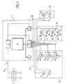
- FIG. 1 is a block diagram of a safety device according to the invention.
- the security device comprises an energy source 2 supplying a circuit 35 extending throughout the device.
- the power source 2 is typically a battery of a motor vehicle. She is associated in parallel with an energy reservoir 3 intended for compensate for a failure of this energy source 2 in shock.
- the safety device also includes a management module 1 for analyzing information on journey and order security mechanisms.
- Source 2 is separated from the management module 1 by a contact switch 4, which allows power on or off voltage.
- the management module 1 is preferably included in an integrated circuit.
- the management module 1 is composed of a power module 5, a unit of treatment 6, of a micro-pulse generator 9, an integrated acceleration sensor 7 and a communication interface 8.
- the power module 5 is intended for supply DC voltage to the rest of the device, from a voltage delivered by energy source 2. It is associated with a regulator (not shown).
- the processing unit 6 is built around a non-volatile memory and a microprocessor. It allows to receive and analyze signals representative of conditions of a trip, and send signals control devices for activating security. Thanks to its non-volatile memory, logic unit 6 also has the function of store trip information.
- the processing unit 6 also includes a internal clock, which allows checking travel conditions periodically. The internal clock also ensures a succession timed system triggers security actuating mechanisms.
- the integrated acceleration sensor 7 is built for example around a piezoelectric element providing logic unit 6 with a signal related to an acceleration of the vehicle.
- This sensor 7 is three-way, from so that we can confirm a detection of a frontal or lateral collision by another acceleration sensor. To this end, the sensor 7 has a slightly higher trigger threshold to that of other sensors. Although a sensor bidirectional is likely to be sufficient for detect frontal and lateral shocks, the use of the three-way sensor 7 brings greater reliability.
- the micro-pulse generator 9 makes it possible to generate electrical pulses precisely calibrated in time and amplitude, used to measure resistances of conductive circuits or semiconductors integrated into initiators safety device pyrotechnics.
- the communication interface 8 allows the management module 1 to receive all information relating to the conditions of the journey, and pass commands to security.
- the communication interface 8 allows also to deliver information to destination of a user.
- An information subset 10 brings together all sources of information necessary for a operation of the management module 1.
- the circuit 35 connects the elements of the subset 10 at the communication interface 8.
- the sub-assembly 10 includes a counter for speed 11, a brake indicator 12, a sensor 13 intended to detect the presence of a passenger, an accelerometer 15 intended to detect a frontal impact and a touch sensor 17 capable of detect a side collision.
- Resistances 14, 16 and 18 are mounted in parallel on sensors 13, 15 and 17 respectively.
- sensors 13, 15 and 17 have an open position and a closed position. In the open position, a current flows through resistors 14, 16 and 18. In the closed position, the sensors 13, 15 and 17 have significantly less resistance. Closing them therefore increases sensitive to a current flowing in the circuit 35. This closure is produced automatically in the presence of a front passenger for the sensor 13, from a frontal impact for the accelerometer 15, and a side collision for the touch sensor 17.
- the information subset 10 constitutes thus a management module input interface 1.
- An actuation sub-assembly 20 gathering all the elements intended to be actuated by management module 1, depending of signals sent by the subset 10, constitutes an interface for output from management module 1. It includes three associated pyrotechnic initiators 21, 22 and 23 respectively to belt pretensioners safety, front airbags and side airbags. These initiators 21, 22, 23 are built around resistive bridges or semiconductors.
- the sub-assembly 20 comprises also a device 24 for unlocking vehicle doors.
- the initiators 21, 22, 23 and the device 24 constitute safety connected to circuit 35 by respectively transistors 25, 26, 27 and 28. These transistors 25, 26, 27, 28 can be in the open position or closed. In the open position, a current circulating in circuit 35 does not reach elements 21, 22, 23, 24. In the closed position, the current flows through it and is capable of triggering them.
- the closure of transistors 25, 26, 27, 28 is controlled by the processing unit 6 by through the communication interface 8.
- the initiators 21, 22, 23, and the device 24 are also connected to the micro-generator of pulses 9, which periodically monitors their functionality.
- the safety device also includes an interface sub-assembly 30 communicating information to a user.
- This subset interface 30 is connected to the interface of communication 8 of the management module 1 by circuit 35 connections. It includes a pilot light 31 located on the dashboard of the vehicle and a read interface 32 intended to read information stored in memory in the processing unit 6.
- the indicator lamp 31 has to report a failure of a sensors.
- Interface 32 makes possible a expertise in the event of an accident or for a control intervention, thus fulfilling a black box or diagnostic function.
- the processing unit 6 Before implementing the management module 1 in a vehicle, the processing unit 6 is factory programmed according to the configuration of this vehicle. It then contains different parameters necessary for its operation. These different parameters can be for example sensor closing threshold values 13, 15 and 17, resistance values of initiators 21, 22, 23 and of device 24, electrical pulse values required to functional tests of these, or still reference voltage values in different measurement points of the circuit 35.
- the contact 4 In normal operation, the contact 4 is closed when switching on vehicle running, putting on the live security. The presence of one or multiple front passengers shutdown of the sensor 13, which causes an increase of one current flowing in circuit 35. The module management 1 detects and interprets this current increase, depending on the value resistance 14.
- management module 1 Periodically, management module 1 tests the state of the initiators 21, 22, 23 and of device 24, thanks to the micro-generator 9. According to whether he checks the functionality of a resistive or semiconductor element, management module 1 proceeds differently.
- a control of a resistive element is carried out by applying a calibrated voltage across its terminals by the micro-generator 9, so that a intensity passing through this resistive element remains lower than its non-operating value.
- the measurement of the intensity generated makes it possible to deduce therefrom resistance of the resistive element, which is compared with its reference value stored in the memory of the processing unit 6.
- the triggering of a security system associated with this semiconductor element is caused by the receipt of a energy having a value greater than a threshold of fixed operation.
- the micro-generator 9 sends a voltage pulse equal to or greater than the value through the semiconductor element, having a sufficiently short that the threshold of operation of the semiconductor element does is not reached.
- the management module 1 in deduces the resistance of this element, that it compare with a reference value.
- the duration of an impulse is typically of the order of a few tens of nanoseconds.
- This last measurement method allows effectively testing semiconductors, without risking inadvertent triggering a security system. This avoids an update fire from a pyrotechnic initiator built around of a semiconductor bridge, while checking good condition.
- the latest results of the checks are stored in the unit's non-volatile memory 6.
- Several tens of moments of tests can for example be saved, the first records being erased as that new ones are made.
- the management module also records periodically measured vehicle speed by the speedometer 11, and the state of braking measured by the brake indicator 12.
- the processing unit 6 permanently contains conditions of course of the journey during the last moments.
- the accelerometer 15 closes.
- the management module 1 detects a significant increase in the current flowing in circuit 35. However, this is not interpreted as representative of a collision front only if the built-in acceleration sensor 7 in turn closes. In case of failure of the sensor 7, the management module 1 is suitable for analyze information from the meter speed 11 to calculate a deceleration representative of a collision. If the closure of the accelerometer 15 is not confirmed by the information from sensor 7 or speedometer 11, it is interpreted as a sensor failure 15. The module management 1 then lights the indicator lamp 31. The tests stored in processing unit 6 can then be viewed through the read interface 32, in order to establish a diagnostic.
- the module management system 1 command as soon as the transistors 25 and 26, causing respectively firing of the pyrotechnic initiators 21 and 22.
- This triggering of initiators 21 and 22 causes a seat belt traction and opening front airbags.
- the transistor 28 is closed in turn, triggering a unlocking doors.
- the management module 1 controls the closing of transistors 25 and 27. The latter causes the cushions to swell side inflatables. Transistor 28 is closed a short time later, like a shock frontal.
- the management module 1 thus plays a role of black box. Possibly, these information can be coded so that limit their access to authorized persons.
- Mechanisms of the same type as those described can be added to individualize their effects.
- several initiators can be provided for airbags separate fronts.
- Other mechanisms of security can be a good idea.
- a battery switch, a fire extinguisher, or a door locking device vehicle can be integrated into the sub-assembly actuation 20.
- a triggering of the mechanisms is caused not by an increase, but by a decrease of current.
- Other methods of transmitting signals are possible, such as methods optical.
Landscapes
- Engineering & Computer Science (AREA)
- Mechanical Engineering (AREA)
- Chemical & Material Sciences (AREA)
- Combustion & Propulsion (AREA)
- Transportation (AREA)
- Air Bags (AREA)
- Automotive Seat Belt Assembly (AREA)
- Lock And Its Accessories (AREA)
Claims (8)
- Sicherheitsvorrichtung für ein Fahrzeug, umfassend:dadurch gekennzeichnet, daß mindestens einer der pyrotechnischen Schalter eine Halbleiterbrücke (25-28) umfaßt, wobei diese Brücke isolierend ist, wenn eine angelegte Spannung kleiner als ein Durchgangswert ist, und leitend ist, wenn die Spannung größer als dieser Wert ist, wobei der Schalter ausgelöst wird, wenn er eine Energie erhält, die einen größeren Wert als eine Funktionsschwelle hat, der Mikro-Impulsgenerator (9) in diesen Schalter Spannungsimpulse sendet, die eine Amplitude aufweisen, die zumindest gleich dem Durchgangswert ist, und eine Dauer aufweisen, die einer Energie entspricht, die kleiner als die Funktionsschwelle ist.Erfassungssysteme (11, 12, 13, 15, 17), die Informationen über Bedingungen einer Strecke des Fahrzeugs liefern, wobei diese Erfassungssysteme (11, 12, 13, 15, 17) einen ersten Zustand, der normalen Streckenbedingungen entspricht, und einen zweiten Zustand, der einer Gefahr für mindestens einen Passagier des Fahrzeugs entspricht, aufweisen,Mechanismen, die aktiviert werden können, um die Sicherheit des Passagiers zu gewährleisten,Sicherheitssysteme (21, 22, 23, 24), die diese Mechanismen aktivieren können, wobei mindestens gewisse dieser Sicherheitssysteme (21, 22, 23) pyrotechnische Schalter umfassen,eine elektrische Versorgungsquelle (2),eine elektrische Schaltung (35), die von der Quelle (2) versorgt wird und an die Erfassungssysteme (11, 12, 13, 15, 17) und an die Sicherheitssysteme (21, 22, 23, 24) angeschlossen ist, die derart beschaffen sind, daß, wenn gewisse der Erfassungssysteme (11, 12, 13, 15, 17) von dem ersten in den zweiten Zustand übergehen, diese die Sicherheitssysteme (21, 22, 23, 24) auslösen, wobei diese Sicherheitssysteme (21, 22, 23, 24) die Mechanismen aktivieren,eine Bearbeitungseinheit (6), die an die Erfassungssysteme (11, 12, 13, 15, 17) und Sicherheitssysteme (21, 22, 23, 24) durch eine Kommunikationsschnittstelle (8) angeschlossen ist, wobei die Bearbeitungseinheit (6) Informationssignale von den Erfassungssystemen (11, 12, 13, 15 17) analysiert und Steuersignale in Richtung der Sicherheitssysteme (21, 22, 23, 24) erzeugt,einen Mikro-Impulsgenerator (9), der es ermöglicht, in der Schaltung (35) elektrische Impulse zu erzeugen, die hinsichtlich Zeit und Amplitude genau kalibriert sind, wobei es diese Impulse ermöglichen, die Funktionalität der pyrotechnischen Schalter zu überprüfen,
- Sicherheitsvorrichtung nach Anspruch 1, dadurch gekennzeichnet, daß die Bearbeitungseinheit (6) einen energieunabhängigen Speicher umfaßt, der es ermöglicht, regelmäßig Informationen über die Funktionalität von Elementen der Sicherheitsvorrichtung aufzuzeichnen.
- Sicherheitsvorrichtung nach Anspruch 1 oder 2, dadurch gekennzeichnet, daß die Mechanismen einer Einheit angehören, die aufblasbare vordere und seitliche Sicherheitskissen, Vorspanner für den Sicherheitsgurt, die eine Spannung der Gurte bewirken können, Vorrichtungen zur Verriegelung und Entriegelung der Fahrzeugtüren, einen Batterieunterbrecher und einen Feuerlöscher umfaßt.
- Sicherheitsvorrichtung nach einem der vorhergehenden Ansprüche, dadurch gekennzeichnet, daß die Erfassungssysteme (11, 12, 13, 15, 17) einer Einheit angehören, die Beschleunigungsmesser (15), einen Geschwindigkeits-messer (11), Tastsensoren (17), Bremsanzeigen (12), Brandanzeiger und Sensoren, die die Anwesenheit von Passagieren anzeigen, aufweist.
- Sicherheitsvorrichtung nach einem der vorhergehenden Ansprüche, dadurch gekennzeichnet, daß sie einen Beschleunigungsmesser (7) umfaßt, der mit den Erfassungssystemen (11, 15, 17) redundant ist, wobei der Beschleunigungsmesser (7) mit der Bearbeitungseinheit (6) verbunden ist und eine von mindestens einem der Erfassungssysteme (11, 15, 17) entdeckte Gefahr bestätigen kann.
- Sicherheitsvorrichtung nach Anspruch 5, dadurch gekennzeichnet, daß der Beschleunigungsmesser (7) dreidirektional ist.
- Sicherheitsvorrichtung nach einem der vorhergehenden Ansprüche, dadurch gekennzeichnet, daß er Mittel (7, 11, 15, 17) umfaßt, die es ermöglichen, Vorder- und Seitenaufpralle zu erfassen.
- Sicherheitsvorrichtung nach einem der vorhergehenden Ansprüche, dadurch gekennzeichnet, daß die Bearbeitungseinheit (6) eine innere Uhr umfaßt, die es ermöglicht, regelmäßig die Bedingungen der Strecke zu überprüfen und aufeinanderfolgende Einschaltungen der Sicherheitssysteme (21, 22, 23, 24) in der Abfolge zu steuern.
Applications Claiming Priority (3)
| Application Number | Priority Date | Filing Date | Title |
|---|---|---|---|
| FR9503856 | 1995-03-31 | ||
| FR9503856A FR2732286B1 (fr) | 1995-03-31 | 1995-03-31 | Dispositif de securite d'un vehicule |
| PCT/FR1996/000491 WO1996030231A1 (fr) | 1995-03-31 | 1996-04-01 | Dispositif de securite d'un vehicule |
Publications (2)
| Publication Number | Publication Date |
|---|---|
| EP0814976A1 EP0814976A1 (de) | 1998-01-07 |
| EP0814976B1 true EP0814976B1 (de) | 2001-10-31 |
Family
ID=9477652
Family Applications (1)
| Application Number | Title | Priority Date | Filing Date |
|---|---|---|---|
| EP96911013A Expired - Lifetime EP0814976B1 (de) | 1995-03-31 | 1996-04-01 | Sicherheitsvorrichtung eines kraftfahrzeuges |
Country Status (7)
| Country | Link |
|---|---|
| US (1) | US6052634A (de) |
| EP (1) | EP0814976B1 (de) |
| JP (1) | JP3776934B2 (de) |
| CA (1) | CA2217398C (de) |
| DE (2) | DE69616527T2 (de) |
| FR (1) | FR2732286B1 (de) |
| WO (1) | WO1996030231A1 (de) |
Families Citing this family (28)
| Publication number | Priority date | Publication date | Assignee | Title |
|---|---|---|---|---|
| DE19646387A1 (de) * | 1996-11-11 | 1998-05-20 | Telefunken Microelectron | Steuerverfahren für ein System, insbesondere für ein Sicherheitssystem in Kraftfahrzeugen |
| JP2001525757A (ja) * | 1997-05-23 | 2001-12-11 | ローベルト ボツシユ ゲゼルシヤフト ミツト ベシユレンクテル ハフツング | バックアップシステム |
| DE59802762D1 (de) * | 1997-10-02 | 2002-02-21 | Siemens Ag | Vorrichtung für den insassenschutz in einem kraftfahrzeug |
| JP3572921B2 (ja) * | 1998-01-06 | 2004-10-06 | 日産自動車株式会社 | エアバック装置 |
| US6120082A (en) * | 1999-03-09 | 2000-09-19 | Navistar International Transportation Corp. | Integrated active seat suspension and seat lockup device |
| US6898498B1 (en) * | 1999-07-06 | 2005-05-24 | Delphi Technologies, Inc. | Crash classification method and apparatus using multiple point crash sensing |
| JP3911933B2 (ja) * | 1999-11-15 | 2007-05-09 | 富士フイルム株式会社 | 安全装置 |
| US20020057542A1 (en) * | 2000-07-31 | 2002-05-16 | Colling Robert E. | Impact activated electronic battery kill switch |
| DE10111266C1 (de) | 2001-03-09 | 2002-04-18 | Bosch Gmbh Robert | Verfahren zur Überprüfung eines Schnittstellenbausteins |
| US6490513B1 (en) | 2001-08-22 | 2002-12-03 | Matsushita Electrical Industrial Co., Ltd. | Automobile data archive system having securely authenticated instrumentation data storage |
| NL1019796C2 (nl) * | 2002-01-21 | 2003-07-23 | Eduard Ronald Mari Plantinga | Een beveiligingssysteem voor het automatisch uitschakelen van airbags e.d. in een voertuig of vaartuig. |
| EP1467897B1 (de) * | 2002-01-23 | 2005-08-10 | Siemens VDO Automotive Corporation | Verfahren und vorrichtung zur bestimmung der entfaltung einer sicherheitsrückhaltevorrichtung in einem insassenrückhaltesystem |
| EP1554162B2 (de) | 2002-10-21 | 2014-03-26 | Autoliv Development Ab | Verbesserungen für eine sicherheitsanordnung für ein fahrzeug oder diese betreffend |
| GB2394584A (en) * | 2002-10-21 | 2004-04-28 | Autoliv Dev | Vehicle safety arrangement |
| DE10312105A1 (de) * | 2003-03-19 | 2004-09-30 | Robert Bosch Gmbh | Vorrichtung zur Ansteuerung von Rückhaltemitteln |
| GB2403935A (en) | 2003-07-17 | 2005-01-19 | Autoliv Dev | Crash detection system with accelerometers at an angle to a vehicles longitudinal axis |
| DE202004009449U1 (de) * | 2004-06-15 | 2004-10-28 | Trw Airbag Systems Gmbh | Gaserzeugende Zusammensetzung |
| US7311169B1 (en) * | 2005-09-22 | 2007-12-25 | Ford Global Technologies, Llc | Door system for automotive vehicle |
| US7596636B2 (en) * | 2005-09-23 | 2009-09-29 | Joseph Gormley | Systems and methods for implementing a vehicle control and interconnection system |
| US7590768B2 (en) * | 2005-09-23 | 2009-09-15 | Joseph Gormley | Control and interconnection system |
| US8694328B1 (en) | 2006-12-14 | 2014-04-08 | Joseph Gormley | Vehicle customization and personalization activities |
| DE102009015711A1 (de) * | 2009-03-31 | 2010-10-07 | Baumer Innotec Ag | Überwachung einer Mikrogeneratorsschaltung einer Drehgebervorrichtung |
| US9156558B2 (en) | 2011-04-05 | 2015-10-13 | Amsafe, Inc. | Inflatable personal restraint systems |
| DE102011084842B4 (de) * | 2011-10-20 | 2017-12-14 | Robert Bosch Gmbh | Verfahren zur Erzeugung einer Freiflughinweisinformation für ein Fahrzeug und Verfahren zur Erkennung eines Freiflugzustandes eines Fahrzeugs |
| US9561767B2 (en) * | 2012-08-21 | 2017-02-07 | Autoliv Development Ab | Drive arrangement for driving a vehicle safety device |
| DE102014207302A1 (de) * | 2014-04-16 | 2015-10-22 | Robert Bosch Gmbh | Verfahren und Vorrichtung zum Abschalten zumindest einer Zündendstufe für eine Zündpille eines pyrotechnischen Schutzmittels für ein Fahrzeug |
| US10391960B2 (en) | 2017-02-28 | 2019-08-27 | Amsafe, Inc. | Electronic module assembly for controlling aircraft restraint systems |
| US11622638B1 (en) | 2021-07-10 | 2023-04-11 | Stabulum Group, LLC | Substrate with integrated multi-layer pouch/pocket |
Family Cites Families (15)
| Publication number | Priority date | Publication date | Assignee | Title |
|---|---|---|---|---|
| FR2467740A1 (fr) * | 1979-10-23 | 1981-04-30 | Renault | Systeme de detection de collisions et de commande de dispositif de securite |
| DE3626601A1 (de) * | 1986-08-06 | 1988-02-18 | Bosch Gmbh Robert | Sicherheitseinrichtung fuer fahrzeuginsassen |
| DE3639065C2 (de) * | 1986-11-14 | 1997-01-09 | Bosch Gmbh Robert | Verfahren zur Überwachung eines rechnergesteuerte Stellglieder ansteuernden Prozeßrechners |
| DE3701681A1 (de) * | 1987-01-22 | 1988-08-04 | Bosch Gmbh Robert | Verfahren zum bidirektionalen signalaustausch zwischen einem rechnersystem und einem abfrageterminal und rechnersystem dafuer |
| DE3738862A1 (de) * | 1987-11-16 | 1989-05-24 | Bosch Gmbh Robert | Verfahren zum betrieb einer sicherheitseinrichtung fuer fahrzeuginsassen |
| DE3811217A1 (de) * | 1988-04-02 | 1989-10-12 | Bosch Gmbh Robert | Elektronische einrichtung |
| DE3942011C3 (de) * | 1989-12-20 | 1996-10-17 | Telefunken Microelectron | Einrichtung zur Auslösung einer passiven Sicherheitseinrichtung für Fahrzeuginsassen |
| JP3177624B2 (ja) * | 1992-09-25 | 2001-06-18 | ボッシュ エレクトロニクス株式会社 | 車両用安全装置の制御システム |
| DE4335991A1 (de) * | 1993-10-21 | 1995-04-27 | Telefunken Microelectron | Auslösevorrichtung für Kfz-Sicherheitssysteme |
| DE4335979A1 (de) * | 1993-10-21 | 1995-04-27 | Telefunken Microelectron | Sicherheits-Management-System (SMS) |
| DE4418293A1 (de) * | 1994-05-26 | 1995-11-30 | Telefunken Microelectron | Verfahren zur Aktivierung einer Endstufe für Sicherheitseinrichtungen eines Kraftfahrzeuges |
| DE4424020A1 (de) * | 1994-07-08 | 1996-01-11 | Telefunken Microelectron | Prüfverfahren für eine passive Sicherheitseinrichtung in Kraftfahrzeugen |
| DE4425845A1 (de) * | 1994-07-21 | 1996-01-25 | Telefunken Microelectron | Datenübertragungsverfahren in einem für den Einsatz in Kraftfahrzeugen geeigneten Datenverarbeitungssystem |
| DE4425846A1 (de) * | 1994-07-21 | 1996-01-25 | Telefunken Microelectron | Verfahren zur Auslösung von Seitenairbags einer passiven Sicherheitseinrichtung für Kraftfahrzeuge |
| US5646454A (en) * | 1994-09-24 | 1997-07-08 | Robert Bosch Gmbh | Electronic safety device for vehicle occupants including a memory device for storing fault conditions and associated control commands |
-
1995
- 1995-03-31 FR FR9503856A patent/FR2732286B1/fr not_active Expired - Fee Related
-
1996
- 1996-04-01 JP JP52903096A patent/JP3776934B2/ja not_active Expired - Fee Related
- 1996-04-01 EP EP96911013A patent/EP0814976B1/de not_active Expired - Lifetime
- 1996-04-01 WO PCT/FR1996/000491 patent/WO1996030231A1/fr not_active Ceased
- 1996-04-01 US US08/930,516 patent/US6052634A/en not_active Expired - Lifetime
- 1996-04-01 CA CA002217398A patent/CA2217398C/fr not_active Expired - Fee Related
- 1996-04-01 DE DE69616527T patent/DE69616527T2/de not_active Expired - Lifetime
- 1996-04-01 DE DE0814976T patent/DE814976T1/de active Pending
Also Published As
| Publication number | Publication date |
|---|---|
| CA2217398C (fr) | 2004-12-07 |
| JP3776934B2 (ja) | 2006-05-24 |
| US6052634A (en) | 2000-04-18 |
| FR2732286A1 (fr) | 1996-10-04 |
| CA2217398A1 (fr) | 1996-10-03 |
| DE814976T1 (de) | 1998-08-13 |
| DE69616527D1 (de) | 2001-12-06 |
| JPH11502795A (ja) | 1999-03-09 |
| WO1996030231A1 (fr) | 1996-10-03 |
| DE69616527T2 (de) | 2002-05-02 |
| FR2732286B1 (fr) | 1997-06-13 |
| EP0814976A1 (de) | 1998-01-07 |
Similar Documents
| Publication | Publication Date | Title |
|---|---|---|
| EP0814976B1 (de) | Sicherheitsvorrichtung eines kraftfahrzeuges | |
| US4958851A (en) | Air bag firing circuit | |
| EP0027747A2 (de) | System zur Aufpralldetektion und zur Steuerung der Sicherheitsvorrichtung | |
| FR2651890A1 (fr) | Dispositif de detection et de discrimination de defauts de fonctionnement d'un circuit d'alimentation electrique. | |
| US5389822A (en) | Triggering circuit for a safety device in motor vehicles | |
| US5261694A (en) | Reconfigurable air bag firing circuit | |
| JPH0659813B2 (ja) | 車両用乗員拘束装置の点火回路 | |
| EP0664528B1 (de) | Verfahren und Vorrichtung zum Vermeiden von Betrügereien in einem mit einem Taxameter ausgerüsteten Taxi oder in einem mit einem Tachographen ausgerüsteten Lastkraftwagen | |
| FR2986398A1 (fr) | Dispositif de securite pour la commande d'un moteur comprenant une redondance des acquisitions d'une mesure de capteurs | |
| CH625962A5 (de) | ||
| FR2896464A1 (fr) | Systeme et procede d'activation pour dispositif de protection de passager | |
| FR3039334B1 (fr) | Procede de securisation du fonctionnement d’un dispositif chauffant | |
| US5136275A (en) | Ground connection monitoring for airbag electrical igniter circuit | |
| EP0897117A1 (de) | Kurzschlusserfassungsgerät für hybride elektrische Fahrzeuge | |
| EP0396654A1 (de) | Gerät und methode zur prüfung von milliohm-impedanzen | |
| CA1062357A (fr) | Procede de controle continu de vitesse pour vehicule moteur et equipement pour la mise en oeuvre de ce procede | |
| FR3080399A1 (fr) | Procede de commande d’une serrure electrique permettant de diagnostiquer une defaillance de la commande d’ouverture associee, commande d’ouverture et vehicule mettant en œuvre un tel procede | |
| FR3105779A1 (fr) | Dispositif et procédé de contrôle automatique de l’état de service d’un système de parachute d’un drone volant. | |
| FR2482229A1 (fr) | Dispositif avertisseur d'usure de garniture de frein pour vehicule automobile | |
| EP0664461A1 (de) | Verfahren und Gerät zur Prüfung eines elektronischen Sensor in einem PkW mit AB | |
| EP1544049A1 (de) | System zur Energieversorgung der funktionellen Elemente des Bordnetzes eines Kraftfahrzeuges | |
| FR2653920A1 (fr) | Systeme d'alarme notamment pour vehicule automobile, a source d'energie electrique autonome. | |
| FR2696240A1 (fr) | Système de commutation autotestable. | |
| Hartl et al. | Airbag Systems-Their Permanent Monitoring and Its Meaning to the User | |
| Härti et al. | Airbag Systems—Their Permanent Monitoring and Its Meaning to the User |
Legal Events
| Date | Code | Title | Description |
|---|---|---|---|
| PUAI | Public reference made under article 153(3) epc to a published international application that has entered the european phase |
Free format text: ORIGINAL CODE: 0009012 |
|
| 17P | Request for examination filed |
Effective date: 19971031 |
|
| AK | Designated contracting states |
Kind code of ref document: A1 Designated state(s): DE GB SE |
|
| GBC | Gb: translation of claims filed (gb section 78(7)/1977) | ||
| DET | De: translation of patent claims | ||
| 17Q | First examination report despatched |
Effective date: 19991117 |
|
| GRAG | Despatch of communication of intention to grant |
Free format text: ORIGINAL CODE: EPIDOS AGRA |
|
| GRAG | Despatch of communication of intention to grant |
Free format text: ORIGINAL CODE: EPIDOS AGRA |
|
| GRAH | Despatch of communication of intention to grant a patent |
Free format text: ORIGINAL CODE: EPIDOS IGRA |
|
| GRAH | Despatch of communication of intention to grant a patent |
Free format text: ORIGINAL CODE: EPIDOS IGRA |
|
| GRAA | (expected) grant |
Free format text: ORIGINAL CODE: 0009210 |
|
| AK | Designated contracting states |
Kind code of ref document: B1 Designated state(s): DE GB SE |
|
| GBT | Gb: translation of ep patent filed (gb section 77(6)(a)/1977) |
Effective date: 20011106 |
|
| REF | Corresponds to: |
Ref document number: 69616527 Country of ref document: DE Date of ref document: 20011206 |
|
| REG | Reference to a national code |
Ref country code: GB Ref legal event code: IF02 |
|
| PLBE | No opposition filed within time limit |
Free format text: ORIGINAL CODE: 0009261 |
|
| STAA | Information on the status of an ep patent application or granted ep patent |
Free format text: STATUS: NO OPPOSITION FILED WITHIN TIME LIMIT |
|
| 26N | No opposition filed | ||
| REG | Reference to a national code |
Ref country code: GB Ref legal event code: 732E Free format text: REGISTERED BETWEEN 20090702 AND 20090708 |
|
| PGFP | Annual fee paid to national office [announced via postgrant information from national office to epo] |
Ref country code: SE Payment date: 20090407 Year of fee payment: 14 |
|
| PGFP | Annual fee paid to national office [announced via postgrant information from national office to epo] |
Ref country code: GB Payment date: 20090401 Year of fee payment: 14 |
|
| EUG | Se: european patent has lapsed | ||
| GBPC | Gb: european patent ceased through non-payment of renewal fee |
Effective date: 20100401 |
|
| PG25 | Lapsed in a contracting state [announced via postgrant information from national office to epo] |
Ref country code: GB Free format text: LAPSE BECAUSE OF NON-PAYMENT OF DUE FEES Effective date: 20100401 |
|
| PGFP | Annual fee paid to national office [announced via postgrant information from national office to epo] |
Ref country code: DE Payment date: 20120430 Year of fee payment: 17 |
|
| PG25 | Lapsed in a contracting state [announced via postgrant information from national office to epo] |
Ref country code: SE Free format text: LAPSE BECAUSE OF NON-PAYMENT OF DUE FEES Effective date: 20100402 |
|
| PG25 | Lapsed in a contracting state [announced via postgrant information from national office to epo] |
Ref country code: DE Free format text: LAPSE BECAUSE OF NON-PAYMENT OF DUE FEES Effective date: 20131101 |
|
| REG | Reference to a national code |
Ref country code: DE Ref legal event code: R119 Ref document number: 69616527 Country of ref document: DE Effective date: 20131101 |