EP0815749B1 - Dispositif de réception d'articles en forme de tige - Google Patents
Dispositif de réception d'articles en forme de tige Download PDFInfo
- Publication number
- EP0815749B1 EP0815749B1 EP97111451A EP97111451A EP0815749B1 EP 0815749 B1 EP0815749 B1 EP 0815749B1 EP 97111451 A EP97111451 A EP 97111451A EP 97111451 A EP97111451 A EP 97111451A EP 0815749 B1 EP0815749 B1 EP 0815749B1
- Authority
- EP
- European Patent Office
- Prior art keywords
- receiving
- drum
- receiving groove
- suction
- rod member
- Prior art date
- Legal status (The legal status is an assumption and is not a legal conclusion. Google has not performed a legal analysis and makes no representation as to the accuracy of the status listed.)
- Expired - Lifetime
Links
- 239000008186 active pharmaceutical agent Substances 0.000 claims description 61
- 238000007599 discharging Methods 0.000 claims description 16
- 230000002093 peripheral effect Effects 0.000 claims description 16
- 238000004140 cleaning Methods 0.000 claims description 4
- 235000019504 cigarettes Nutrition 0.000 description 125
- 238000004519 manufacturing process Methods 0.000 description 16
- 238000005096 rolling process Methods 0.000 description 7
- 238000000034 method Methods 0.000 description 6
- 230000008569 process Effects 0.000 description 6
- 230000007246 mechanism Effects 0.000 description 5
- 238000000926 separation method Methods 0.000 description 5
- 230000008859 change Effects 0.000 description 4
- 241000208125 Nicotiana Species 0.000 description 3
- 235000002637 Nicotiana tabacum Nutrition 0.000 description 3
- 238000005520 cutting process Methods 0.000 description 3
- 239000006185 dispersion Substances 0.000 description 3
- 230000008878 coupling Effects 0.000 description 2
- 238000010168 coupling process Methods 0.000 description 2
- 238000005859 coupling reaction Methods 0.000 description 2
- 238000006073 displacement reaction Methods 0.000 description 2
- 239000000428 dust Substances 0.000 description 2
- DGLFSNZWRYADFC-UHFFFAOYSA-N chembl2334586 Chemical compound C1CCC2=CN=C(N)N=C2C2=C1NC1=CC=C(C#CC(C)(O)C)C=C12 DGLFSNZWRYADFC-UHFFFAOYSA-N 0.000 description 1
- 239000013256 coordination polymer Substances 0.000 description 1
- 238000012986 modification Methods 0.000 description 1
- 230000004048 modification Effects 0.000 description 1
- 238000012856 packing Methods 0.000 description 1
- 238000004804 winding Methods 0.000 description 1
Images



Classifications
-
- A—HUMAN NECESSITIES
- A24—TOBACCO; CIGARS; CIGARETTES; SIMULATED SMOKING DEVICES; SMOKERS' REQUISITES
- A24C—MACHINES FOR MAKING CIGARS OR CIGARETTES
- A24C5/00—Making cigarettes; Making tipping materials for, or attaching filters or mouthpieces to, cigars or cigarettes
- A24C5/32—Separating, ordering, counting or examining cigarettes; Regulating the feeding of tobacco according to rod or cigarette condition
- A24C5/322—Transporting cigarettes during manufacturing
- A24C5/327—Construction details of the cigarette transport drum
-
- A—HUMAN NECESSITIES
- A24—TOBACCO; CIGARS; CIGARETTES; SIMULATED SMOKING DEVICES; SMOKERS' REQUISITES
- A24C—MACHINES FOR MAKING CIGARS OR CIGARETTES
- A24C5/00—Making cigarettes; Making tipping materials for, or attaching filters or mouthpieces to, cigars or cigarettes
- A24C5/32—Separating, ordering, counting or examining cigarettes; Regulating the feeding of tobacco according to rod or cigarette condition
- A24C5/322—Transporting cigarettes during manufacturing
- A24C5/326—Transporting cigarettes during manufacturing with lateral transferring means
Definitions
- the present invention relates to a receiving device for receiving a rod member conveyed on a conveying path in an axial direction thereof according to the preamble of claim 1 and as it is disclosed in GB-A-1 409 814.
- the new device is to receive rod members one by one and to change the transportation direction thereof to be received into another transportation path. Further, the new receiving device is to be suitable for reception of double cigarettes from a cigarette manufacturing machine as a catcher device thereof.
- a filter cigarette manufacturing machine a so-called filter attachment has a catcher drum.
- the catcher drum can receive double cigarettes one by one from a cigarette manufacturing machine.
- the cigarette manufacturing device has a conveying path extending toward the filter attachment. The conveying path guides the individual double cigarette delivered from a cutting section of the cigarette manufacturing machine in the axial direction of the double cigarette.
- the catcher drum has many receiving grooves on an outer peripheral surface thereof. These receiving grooves are arranged at equal intervals in a circumferential direction of the catcher drum. Each of the receiving grooves is sequentially aligned with the conveying path of the cigarette manufacturing machine as the catcher drum rotates, each of the receiving grooves can receive one double cigarette from the conveying path through an opening at one end of the receiving groove. Thereafter, the double cigarette in the receiving groove is transported in a direction perpendicular to the axial direction of the double cigarette as the catcher drum rotates. Namely, the double cigarette is transferred from the conveying path of the cigarette manufacturing machine onto the catcher drum so that the conveying posture of the double cigarette is switched.
- the double cigarette transferred onto the catch drum advances in the receiving groove.
- the double cigarette receives braking force instead mechanically by a spring blade, as disclosed in GB-A-1 032 413, pneumatically by suction in the receiving groove and is temporarily stopped.
- the double cigarette is moved by positioning means and is positioned in a regular position in the receiving groove.
- the positioning means may includes a stopper arranged on the other end side of the receiving groove or the regular position and pulling means for pulling the double cigarette in the temporary stopping state by suction until the double cigarette comes in contact with the stopper.
- the braking force and pulling force for the double cigarette are respectively provided by suction, respectively, when the double cigarette is temporarily stopped in the receiving groove and the double cigarette is moved from the temporary stopping position to the stopper. It is difficult to constantly maintain the braking force and the pulling force at any time.
- the temporary stopping position of the double cigarette is also changed in the receiving groove by a change in the braking force. For example, when the temporary stopping position of the double cigarette is separated far from the stopper, no pulling force of the pulling means can be moved until the double cigarette comes in contact with the stopper. Accordingly, no double cigarette can be accurately positioned in the receiving groove.
- the above-mentioned problems are also caused by a change in size of the double cigarette as well as changes in the braking force and the pulling force. Namely, when the double cigarette is changed in weight, the braking force and the pulling force for the double cigarette must be adjusted in accordance with the weight of the double cigarette. However, much labor and time are required to make this adjustment.
- An object of the present invention is to provide a receiving device for rod members, which can accurately position the received rod member even when suction force is changed, and can sufficiently cope with rod members having different lengths or weights.
- the device comprises a receiving drum rotatably arranged on a terminal end side of a conveying path for a rod member, the receiving drum including an outer peripheral surface moved in a direction crossing the conveying path and receiving grooves formed on the outer peripheral surface of the receiving drum at equal intervals in a circumferential direction.
- Each of the receiving grooves sequentially pass through a receiving position opposed to a terminal end of the conveying path as the receiving drum rotates, whereby each of the receiving grooves receives the rod member delivered from the conveying path through an inlet thereof and allows the received rod member to advance in an axial direction of the receiving drum.
- the receiving device further comprises braking means for applying braking force to the rod member in the receiving groove and stopping the advance of the rod member, and positioning means for pushing back the rod member stopped in the receiving groove toward the inlet of the receiving groove and positioning the rod member in a normal position defined in the receiving groove.
- the positioning means includes a pusher movably arranged in each receiving groove, the pusher having a rest position separated by a predetermined distance from the rod member stopped by the braking means.
- a receiving groove of the drum receives the rod member from the conveying path when the receiving groove reaches the receiving position, i.e., when the inlet of the receiving groove and the conveying path are opposed to each other.
- the received rod member advances in the receiving groove.
- the rod member receives the braking force and is temporarily stopped in a position overrunning from the normal position. Thereafter, the rod member in the temporary stopping state is pushed back toward the inlet side of the receiving groove by the pusher and is positioned in the normal position.
- the rod member is accurately positioned in the normal position even when there is a little dispersion in the temporary stopping position of the rod member in the receiving groove.
- the braking means can include a cover for covering the outer peripheral surface of the receiving drum and extending from the receiving position in the circumferential direction of the receiving drum with respect to a rotating direction of the receiving drum.
- this receiving groove forms a tunnel in cooperation with the cover.
- the braking means further includes sucking holes formed on a bottom surface of each receiving groove, and first suction means for applying first suction to the suction holes in a predetermined angular region of the receiving drum after the receiving groove moves into the cover.
- the rod member advancing in the receiving groove is braked by the suction from the suction holes and is temporarily stopped.
- the braking means can further include discharging means for discharging air in the receiving groove and pulling the rod member in the receiving groove toward a temporary stopping position, and the discharging means has a discharging port formed in the cover.
- discharging means for discharging air in the receiving groove and pulling the rod member in the receiving groove toward a temporary stopping position
- the discharging means has a discharging port formed in the cover.
- the discharging port can be arranged in the receiving position with respect to the a circumferential direction of the cover. In this case, when the receiving groove passes through the receiving position, the air in the receiving groove is discharged through the discharging port.
- the discharging means preferably further has adjusting means for adjusting discharging force for the receiving groove.
- the positioning means further includes reciprocating means for reciprocating the pusher in the receiving groove at a predetermined stroke.
- the reciprocating means can be realized by cam means utilizing rotation of the receiving drum.
- the cam means allows the pusher to come in contact with the rod member before a moving speed of the pusher becomes a maximum speed thereof when the pusher is moved from its rest position toward the rod member. Therefore, the pusher slowly comes in contact with the rod member so that no cut end of the rod member is damaged.
- the positioning means can further include second suction means for applying second suction to the sucking holes of the receiving groove and holding the rod member in the receiving groove, and the second suction is weaker than the braking force provided by the first suction.
- the pusher pushes back the rod member against the holding force provided by the second suction.
- the receiving device can further include cleaning means for cleaning the interior of the receiving groove by compressed air before each receiving groove reaches the receiving position. Since the receiving groove passing through the receiving position is in an already cleaned state, the rod member in the receiving groove is smoothly advanced and pushed back without having any bad influence by dust in the receiving groove.
- a filter attachment has a drum train 2 extending in a horizontal direction.
- the drum train 2 includes plural grooved drums adjacent to each other.
- a grooved drum located at a right-hand end of the drum train 2 in FIG. 1 is used as a catcher drum 4.
- a conveying path (not shown) of a cigarette manufacturing machine (not shown) extends to a portion near the catcher drum 4.
- the catcher drum 4 can receive double cigarettes one by one from the conveying path of the cigarette manufacturing machine.
- Each of the double cigarette has a length twice the length of a cigarette portion in a filter cigarette.
- the drum train 2 includes a grooved drum having a rotary knife, i.e., a knife drum.
- a rotary knife i.e., a knife drum.
- the double cigarette passes through the knife drum, the double cigarette is cut into two equal lengths so that left-hand and right-hand single cigarettes are obtained.
- two grooved drums located on a downstream side from the knife drum in the drum train 2 are constructed as separation drums. When the left-hand and right-hand single cigarettes pass through the separation drums, the left-hand and right-hand single cigarettes are separated from each other in an axial direction thereof.
- reference symbols DS and SS designate a double cigarette and a single cigarette, respectively.
- a filter supplying device 8 is arranged above the drum train 2 and has a hopper 10 for filter rods.
- a drum train 12 connects the hopper 10 and the drum train 2 to each other.
- the filter rods taken out of the hopper 10 one by one are sequentially transferred to an adjacent grooved drum in the drum train 12 and is transported toward the drum train 2.
- the filter rod is cut into filter plugs having a predetermined length during the transportation thereof.
- the individual filter plug is supplied to a grooved drum downstream from the separation drums in the drum train 2, i.e., a collecting drum.
- the left-hand and right-hand single cigarettes and one filter plug are arranged on the same line on the collecting drum in a state in which the filter plug is arranged between the two single cigarettes.
- the left-hand and right-hand single cigarettes come in close contact with both ends of the filter plug and become one rod unit. Thereafter, the rod units are supplied to the rolling section 6.
- the rod unit and a tip paper piece are simultaneously supplied to the rolling section 6.
- One face of the tip paper piece is coated with paste.
- the filter plug of the rod unit is connected to the left-hand and right-hand single cigarettes by the winding of the tip paper piece.
- a double filter cigarette constructed by two filter cigarettes is formed.
- the processes described so far are shown in a region A 2 in FIG. 2.
- reference symbols FP, CP and DFS designate a filter plug, a tip paper piece and a double filter cigarette, respectively.
- the tip paper piece is obtained by cutting tip paper a predetermined length and the tip paper is drawn out of a roll.
- a drum train 14 is arranged on a side opposed to the drum train 2 and also extends from the rolling section 6 in the horizontal direction.
- the double filter cigarette formed in the rolling section 6 is transported on the drum train 14.
- the double filter cigarette is equally cut from its center by the rotary knife.
- individual filter cigarettes are obtained and are separated from each other leftward and rightward. This process is shown in a region A 3 in FIG. 2.
- reference symbol FS designates filter cigarettes. Thereafter, the filter cigarettes are transported toward a packing machine (not shown) through a conveyer 16.
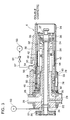
- the catcher drum 4 has a horizontal drum shaft 20.
- the drum shaft 20 extends through a fixing sleeve 22 and is rotatably supported through a pair of bearings 24 with respect to the fixing sleeve 22.
- a predetermined clearance is secured between the fixing sleeve 22 and the drum shaft 20.
- the fixing sleeve 22 horizontally extends from a main frame 26 of the filter attachment and has one end portion airtightly fitted into the main frame 26. Namely, the fixing sleeve 22 is supported by the main frame 26 in its one end portion.
- Negative pressure passages 28, 29 are defined in the main frame 26 and are separated from each other. Each of the negative pressure passages 28, 29 is connected to a corresponding negative pressure source (not shown) at any time. Here, a negative pressure supplied to the negative pressure passage 28 is stronger than that supplied to the negative pressure passage 29.
- the drum shaft 20 is projected from each of both ends of the fixing sleeve 22.
- a gear 30 is attached to one end of the drum shaft 20 on the side of the main frame 26. Rotating force can be inputted from an power transmitting system (not shown) to the gear 30. Accordingly, when the rotating force is inputted to the gear 30, the drum shaft 20 is rotated in a predetermined direction through the gear 30.
- a control sleeve 32 is fixed on the fixing sleeve 22 and extends from a portion near the main frame 26 to the other end of the fixing sleeve 22. Further, a drum shell 34 is rotatably attached onto the control sleeve 32 and covers the fixing sleeve 32. One end of the drum shell 34 is rotatably supported on the fixing sleeve 22 through a bearing 35. Another end portion of the drum shell 34 greatly exceeds the control sleeve 32 and projects.
- the other end of the drum shaft 20 and the drum shell 34 are detachably coupled to each other through a coupling mechanism 37. Accordingly, the drum shell 34 can be rotated together with the drum shaft 20.
- An explanation with respect to the coupling mechanism 37 is omitted.
- Many receiving grooves 36 are formed on an outer peripheral surface of the drum shell 34 and are arranged in the half of the drum shell 34 separated far from the main frame 26.
- the receiving grooves 36 are arranged at equal intervals in a circumferential direction of the drum shell 34 and have inlets opened at the other end of the drum shell 34.
- each of the receiving grooves 36 reaches a predetermined rotating angle position, i.e., a receiving position as the drum shell 34 rotates, the receiving groove 36 is located on the same line as the above-mentioned conveying path of the cigarette manufacturing machine.
- the double cigarette manufactured by the cigarette manufacturing machine is intermittently delivered on its conveying path.
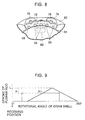
- the receiving grooves 36 are shown on an enlarged scale in FIG. 4. Both side walls of each receiving groove 36 are not parallel to each other in an inlet portion thereof. A side wall of the receiving groove 36 located backward with respect to a rotating direction of the drum shell 34 is inclined to enlarge the width of the inlet of the receiving groove 36. An arrow A in FIG. 4 shows the rotating direction of the drum shell 34.
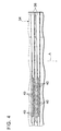
- a shell cover 38 is arranged outside the drum shell 34. As can be seen from FIG. 3, the shell cover 38 covers all regions of the drum shell 34 seen from the axial direction of the drum shell 34. However, as can be seen from FIG. 5, the shell cover 38 covers only one portion of the outer peripheral surface of the drum shell 34 with respect to the circumferential direction thereof. More specifically, the shell cover 38 extends from a position just before the above-mentioned receiving position of the receiving groove 36 seen from the circumferential direction of the drum shell 34 to a predetermined rotating angle position in the rotating direction of the drum shell 34.
- each receiving groove 36 When each receiving groove 36 enters the shell covers 38 as the drum shell 34 rotates, the receiving groove 36 forms a tunnel passage in cooperation with the shell cover 38.
- each receiving groove 36 has many suction holes 40 on the bottom surface thereof.
- These suction holes 40 define a suction region extending in the axial direction of the receiving groove 36. More specifically, the suction holes 40 are arranged at equal intervals in the axial direction of the receiving groove 36. It is secured that the suction region is longer than the entire length of the double cigarette.
- Each of the suction holes 40 extends in a radial direction in the drum shell 34 and is opened on an inner peripheral surface of the drum shell 34.
- a first suction slot 42 and a second suction slot 44 are respectively formed in the control sleeve 32 in axial positions corresponding to the suction region of the receiving grooves 36.
- the first suction slot 42 extends from the above-mentioned receiving position of the drum shell 34 to a first angular region ⁇ 1 (for example, 60°) with respect to the rotating direction of the drum shell 34.
- the first angular region ⁇ 1 is included within a region covered by the shell cover 38.
- the second suction slot 44 extends from a portion near the first suction slot 42 to a second angular region ⁇ 2 (for example 240°) in the the rotating direction of the drum shell 34.
- a width of the second suction slot 44 with respect to the axial direction of the control sleeve 32 is narrower than that of the first suction slot 42.
- One side edges of the first and second suction slots 42, 44, which are separated far from the inlet of the receiving groove 36, are located on the same circumference of a circle.
- An atmospheric groove 43 is further formed on the outer peripheral surface of the control sleeve 32.
- the atmospheric groove 43 is located behind the second suction slot 44 over a third angular region ⁇ 3 (see FIG. 5) with respect to the rotating direction of the drum shell 34. As can be seen from FIG. 6, a slight clearance is secured between the atmospheric groove 43 and the second suction slot 44.
- the atmospheric groove 43 extends in the axial direction of the control sleeve 32 and one end of the atmospheric groove 43 is communicated with the atmosphere.
- Suction grooves 46, 48 are respectively formed on the outer peripheral surface of the fixing sleeve 22. As can be seen from FIG. 6, the suction grooves 46, 48 are connected to the first and second suction slots 42, 44 of the control sleeve 32, respectively.
- the suction groove 46 is communicated with the negative pressure passage 28 in the main frame 26 through an internal passage 45 formed in the fixing sleeve 22.
- the suction groove 48 is communicated with the negative pressure passage 29 in the main frame 26 through an internal passage 55 formed in the fixing sleeve 22. Therefore, the suction grooves 46, 48 can respectively receive negative pressures from the negative pressure passages 28, 29.
- the negative pressures in the sucking grooves 46, 48 are therefore supplied to the first and second suction slots 42, 44, respectively.
- a negative pressure difference is kept between the pressures in the negative pressure passages 28 and 29. Therefore, the negative pressure supplied into the second suction slot 44 is weaker than that supplied into the first suction slot 42.
- an inner blow tube 50 extends into the fixing sleeve 22 and is shown by a two-dotted chain line in FIG. 3. As shown in FIG. 3, one end of the inner blow tube 50 is projected outside from one end face of the fixing sleeve 22 and is connected to an outer blow tube 51 through a connector. The outer blow tube 51 is connected to a pneumatic source 53. As shown in FIG. 6, the other end of the inner blow tube 50 is opened into a blow groove 49. The blow groove 49 is formed on the outer peripheral surface of the fixing sleeve 22.
- a blow slot 47 is further formed in the control sleeve 32. The blow slot 47 extends from the blow groove 49 and is opened on the outer peripheral surface of the control sleeve 32.
- the blow slot 47 is located between the atmospheric groove 43 and the first suction slot 42 with respect to the rotating direction of the drum shell 34. Namely, the blow slot 47 is located within a fourth angular region ⁇ 4 (see FIG. 5) between the third angular region ⁇ 3 and the first angular region ⁇ 1 mentioned above.
- a suction opening 54 is formed in the shell cover 38.
- the suction opening 54 is located at the above-mentioned receiving position with respect to the circumferential direction of the drum shell 34.
- the suction opening 54 is located at a position corresponding to the inner end of the above-mentioned suction region, i.e., inside edges of the first and second suction slots 42, 44 with respect to the axial direction of the receiving grove 36.
- the suction opening 54 is connected to a suction tube 57 through a connector 56.
- the suction tube 57 is connected to an air sucking source 59 and a pressure adjusting valve 61 is inserted in the suction tube 57.
- a pusher rod 58 is arranged in each receiving groove 36 and can be moved within the receiving groove 36 in the axial direction thereof.
- the pusher rod 58 is located between the inner end of the receiving groove 36 and the suction region thereof.
- Each pusher rod 58 can be reciprocated in the corresponding receiving groove 36 through a cam mechanism 60 as the drum shell 34 rotates.
- the cam mechanism 60 will next be explained.
- the cam mechanism 60 has a cylindrical cam 62 fixed to the outer peripheral surface of the fixing sleeve 22. More specifically, the cylindrical cam 62 is also used as one end portion of the control sleeve 32, i.e., one end portion thereof on the side of the main frame 26. The cylindrical cam 62 may be a separate member from the control sleeve 32.
- a cam groove 66 is formed on an outer peripheral surface of the cylindrical cam 62 and is formed in an entire circumference of the cylindrical cam 62. A position of the cam groove 66 in the axial direction of the cylindrical cam 62 is changed in accordance with the angular displacement of the drum shell 34.
- Cam followers 68 are fitted into the cam groove 66.
- Each of the cam followers 68 is made of a roller.
- Each of the cam followers 68 is rotatably mounted on a shaft 70 which is projected outside in a radial direction of the cylindrical cam 62.
- a connecting plate 72 is mounted on the shaft 70 and a pusher holder 76 is connected to the connecting plate 72 through a pair of connecting screws 74.
- the shaft 70 and the connecting plate 72 are arranged within a corresponding slot 64 of the drum shell 34. These slot 64 are formed in one end portion of the drum shell 34 and arranged at predetermined intervals in the circumferential direction of the drum shell 34.
- each pusher holder extends along the circumferential direction of the drum shell 34 and is movably supported by a pair of guide rods 78.
- the pair of guide rods 78 are separated from each other in the circumferential direction of the drum shell 34 and extend in the axial direction of the drum shell 34.
- both ends of the guide rods 78 are respectively supported by a pair of rings 80, 82.
- These rings 80, 82 are arranged on the drum shell 34 and can be rotated integrally with the drum shell 34.
- each pusher rod 58 is attached to each pusher holder 76 (see FIG. 8), respectively. More specifically, as shown in FIG. 7, a proximal end of each of the pusher rods 58 is connected to the pusher holder 76 through a pair of connecting screws 84 and a distal end portion of each of the pusher rods 58 passes through the ring 80. Notches are therefore formed in an arc shape on an inner surface of the ring 80 and allow the passing of each of the pusher rods 58.
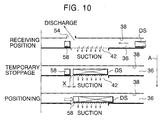
- a change in stroke of the pusher rod 58 with respect to the angular displacement of the drum shell 34 is shown in FIG. 9.
- a maximum stroke L of the pusher rod 58 is set to 40 cm.
- a rotational angle 0° of the drum shell 34 shows the above-mentioned receiving position.
- the receiving groove 36 When one receiving groove 36 reaches the receiving position as the drum shell 34 rotates, the receiving groove 36 forms a tunnel passage in cooperation with the shell cover 38 (see FIG. 5). At this time, as shown in FIG. 10, a double cigarette DS is delivered from the conveying path of the cigarette manufacturing machine into the receiving groove 36. Thereafter, the received double cigarette DS advances within the receiving groove 36 toward the pusher rod 58 in the rest position.
- the double cigarette DS is delivered from the conveying path of the cigarette manufacturing machine by a kicker device (not shown). More specifically, when the double cigarette DS is delivered from the conveying path of the cigarette manufacturing machine, the receiving groove 36 passes through the receiving position at the same time. The receiving grooves 36 can therefore receive the double cigarettes DS one by one while the drum shell 34 rotates.
- the receiving groove 36 When the receiving groove 36 passes through the receiving position, the receiving groove 36 is connected to the suction opening 54 and the suction holes 40 of the receiving groove 36 are communicated with the first suction slot 42 of the control sleeve 32. Therefore, as shown in FIG. 10, the air in the receiving groove 36 is discharged from the suction opening 54 and the suction holes 40. As a result, the double cigarette DS entered into the receiving groove 36 is pulled toward the pusher rod 58.
- an approaching speed of the double cigarette DS from the conveying path is low at a start-up time of the operation of the cigarette manufacturing machine and in a low speed operating thereof.
- the air in the receiving groove 36 is discharged from both the suction holes 40 and the suction opening 54. Accordingly, this discharged air assists the advance of the double cigarette DS so that the double cigarette DS can be reliably moved toward the pusher rod 58.
- the double cigarette DS in the receiving groove 36 enters a region of the suction holes 40, the discharged air from the suction holes 40, i.e., suction is applied as braking force to the double cigarette DS.
- suction is applied as braking force to the double cigarette DS.
- the double cigarette DS receives the braking force by the suction so that the double cigarette DS is temporarily stopped in the suction region in the receiving groove 36.
- the temporary stopping of the double cigarette DS is kept while the receiving groove 36 is moved within the first angular region ⁇ 1 of the drum shell 34.
- the clearance X between the double cigarette DS in a temporary stopping position and the pusher rod 58 is preferably limited to 1/4 (e.g., 10 cm) of a maximum stroke L or less of the pusher rod 58.
- the temporary stopping position of the double cigarette DS is set between the pusher rod 58 in the rest position and a normal position of the double cigarette described later. Accordingly, the double cigarette DS overruns the normal position and then is temporarily stopped.
- the receiving groove 36 together with the double cigarette DS, enters from the first angular region ⁇ 1 to the second angular region ⁇ 2 and moves within this second angular angle region ⁇ 2.
- the sucking holes 40 of the receiving groove 36 are communicated with the second suction slot 44 instead of the first suction slot 42.
- the negative pressure supplied to the second suction slot 44 is weaker than that supplied to the first suction slot 42 so that suction force of the double cigarette DS in the receiving groove 36 is reduced.
- the double cigarette DS can be sufficiently held in the receiving groove 36 by the suction force applied to the double cigarette DS. Accordingly, no double cigarette DS drops from the receiving groove 36.
- the pusher rod 58 in the receiving groove 36 is started to move from the rest position thereof at this time toward the double cigarette DS. Thereafter, as shown in FIG. 10, when the distal end of the pusher rod 58 comes in contact with the double cigarette DS in the temporary stopping state, the pusher rod 58 pushes back the double cigarette DS against holding force provided through the suction holes 40 until the pusher rod 58 reaches the maximum stroke L thereof. Thus, the double cigarette DS is moved until the normal position and is accurately positioned in this normal position.
- the five pusher rods 58 are attached to the pusher holder 76 so that every five double cigarettes DS are positioned on the drum shell 34 at the same time.
- the clearance X between the pusher rod 58 in the rest position and the double cigarette DS in the temporary stopping position is limited to about 1/4 of the maximum stroke L of the pusher rod 58. Therefore, when the distal end of the pusher rod 58 pushes back the double cigarette DS, a pushing-out speed of the pusher rod 58 does not still reach its maximum speed. Accordingly, the distal end of the pusher rod 58 comes in soft contact with the double cigarette DS so that this contact does not damage the cut end of the double cigarette DS.
- the double cigarette DS When the double cigarette DS is pushed back until the normal position, the double cigarette DS is merely held by a relatively weak negative pressure, i.e., holding force. Therefore, the double cigarette DS is smoothly pushed back by the pusher rod 58.
- the double cigarette DS is finally positioned mechanically by the pusher rod 58. Accordingly, when a slight dispersion in the temporary stopping position of the double cigarette DS is caused, the double cigarette DS is accurately positioned in the normal position irrespective of this dispersion.
- the suction holes 40 of the receiving groove 36 are communicated with the atmospheric groove 43.
- the double cigarette DS in the receiving groove 36 is transferred to the next grooved drum adjacent to the catcher drum 4 in the drum train 2 simultaneously when the suction force of the double cigarette DS is released.
- the double cigarette DS is then conveyed toward the rolling section 6 on the drum train 2.
- the pusher rod 58 is returned toward the rest position in the receiving groove 36. As can be seen from FIG. 9, the pusher rod 58 is returned to the rest position just before the receiving groove 36 reaches the receiving position next time.
- the suction holes 40 of the receiving groove 36 are connected to the blow slot 47 and receives compressed air supplied from this blow slot 47. Accordingly, the compressed air is ejected from the suction holes 40 of the receiving groove 36 and cleans the interior of the receiving groove 36.
- the advance of the double cigarette DS in the receiving groove 36 and the pushing-back of the double cigarette DS using the pusher rod 58 are not prevented by wastes of shredded tobacco, dust, etc. in the receiving groove 36.
- No application of the receiving device according to the present invention is limited to the catcher drum of the above-mentioned filter attachment, but this receiving device can be applied to a catcher drum for receiving various kinds of rod members.
Landscapes
- Manufacturing Of Cigar And Cigarette Tobacco (AREA)
Claims (9)
- Dispositif de réception servant à recevoir un élément en forme de tige (DS) convoyé sur un trajet de convoyage dans une direction axiale de ce dernier, ledit dispositif de réception comprenant un tambour de réception (4) monté de manière à pouvoir tourner sur un côté d'extrémité du trajet de convoyage, ledit tambour de réception (4) comprenant une surface périphérique extérieure déplacée dans une direction qui croise le trajet de convoyage, et des rainures de réception (36) formées sur la surface périphérique extérieure dudit tambour de réception (4), à des intervalles égaux dans une direction circonférentielle de ce tambour, chacune des rainures de réception (36) passant successivement par une position de réception située en vis-à-vis de l'extrémité finale du trajet de convoyage lorsque ledit tambour de réception (4) tourne, de sorte que chacune des rainures de réception (36) reçoit l'élément en forme de tige (DS) délivré par le trajet de convoyage, par une entrée de ce dernier et permet à l'élément formant tige DS reçu d'avancer dans une direction axiale dudit tambour de réception (4); et des moyens de positionnement pour positionner l'élément en forme de tige (DS) reçu dans une position normale définie par la rainure de réception (36), lesdits moyens de positionnement comprenant des moyens de freinage (40, 42) pour appliquer une force pneumatique à l'élément en forme de tige (DS) dans la rainure de réception (36),
caractérisé en ce que lesdits moyens de positionnement incluent en outre un poussoir (58) disposé dans chacune des rainures de réception (36) et se déplaçant en va-et-vient entre la position normale et une position de repos séparées d'une distance prédéterminée en direction du côté opposé de ladite entrée, l'avance de l'élément en forme de tige (DS) dans une position située entre ladite position normale et ladite position de repos étant arrêtée par lesdits moyens de freinage (40, 42). - Dispositif selon la revendication 1, caractérisé en ce que les moyens de freinage incluent un capot (38) servant à recouvrir la surface périphérique extérieure dudit tambour de réception (4) de manière à s'étendre depuis la position de réception dans la direction circonférentielle dudit tambour de réception (4) par rapport à un sens de rotation dudit tambour de réception (4) de sorte que la rainure de réception (36) située dans le capot (38) est agencée avec une forme de tunnel;des trous d'aspiration (40) formés dans une surface inférieure de chacune des rainures de réception (36); etdes premiers moyens d'aspiration (42) pour appliquer une première aspiration aux trous d'aspiration (40) dans une zone angulaire prédéterminée (α1) dudit tambour de réception (4) une fois que la rainure de réception (36) a pénétré dans le capot (38), la première aspiration produisant la force de freinage.
- Dispositif selon la revendication 2, caractérisé en ce que lesdits moyens de freinage comprennent en outre des moyens d'évacuation (54, 59) pour évacuer l'air situé dans la rainure de réception (36) et tirer l'élément en forme de tige (DS) dans la rainure de réception (36) en direction d'une position d'arrêt temporaire, les moyens d'évacuation possédant un orifice d'évacuation (54) formé dans le capot (38).
- Dispositif selon la revendication 3, caractérisé en ce que l'orifice d'évacuation (54) est disposé dans la position de réception par rapport à une direction circonférentielle du capot (38).
- Dispositif selon la revendication 3, caractérisé en ce que les moyens d'évacuation comprennent en outre des moyens de réglage (61) pour régler la force d'évacuation pour la rainure de réception (36).
- Dispositif selon la revendication 1, caractérisé en ce que les moyens d'entraínement en va-et-vient possèdent des moyens formant came (60) utilisant la rotation dudit tambour de réception (4) pour le déplacement en va-et-vient du poussoir (58).
- Dispositif selon la revendication 6, caractérisé en ce que les moyens formant came permettent au poussoir (58) de venir en contact avec l'élément formant tige (DS) avant qu'une vitesse de déplacement du poussoir (58) devienne sa vitesse maximale lorsque le poussoir (58) est déplacé depuis la position de repos en direction de l'élément en forme de tige (DS).
- Dispositif selon la revendication 6, caractérisé en ce que lesdits moyens de positionnement comprennent en outre des seconds moyens d'aspiration (44) pour appliquer une seconde aspiration aux trous d'aspiration (40) de la rainure de réception (36) et retenir l'élément en forme de tige (DS) dans la rainure de réception (36), la seconde aspiration étant inférieure à la force de freinage.
- Dispositif selon la revendication 1, caractérisé en ce que ledit dispositif comporte en outre des moyens de nettoyage (47) pour nettoyer l'intérieur de la rainure de réception (36) à l'aide d'air comprimé avant que chacune des rainures de réception (36) n'atteigne la position de réception.
Applications Claiming Priority (3)
| Application Number | Priority Date | Filing Date | Title |
|---|---|---|---|
| JP176825/96 | 1996-07-05 | ||
| JP17682596A JP3368148B2 (ja) | 1996-07-05 | 1996-07-05 | ロッド部材の受け取り装置 |
| JP17682596 | 1996-07-05 |
Publications (2)
| Publication Number | Publication Date |
|---|---|
| EP0815749A1 EP0815749A1 (fr) | 1998-01-07 |
| EP0815749B1 true EP0815749B1 (fr) | 2001-10-24 |
Family
ID=16020507
Family Applications (1)
| Application Number | Title | Priority Date | Filing Date |
|---|---|---|---|
| EP97111451A Expired - Lifetime EP0815749B1 (fr) | 1996-07-05 | 1997-07-07 | Dispositif de réception d'articles en forme de tige |
Country Status (4)
| Country | Link |
|---|---|
| US (1) | US5931278A (fr) |
| EP (1) | EP0815749B1 (fr) |
| JP (1) | JP3368148B2 (fr) |
| DE (1) | DE69707569T2 (fr) |
Families Citing this family (16)
| Publication number | Priority date | Publication date | Assignee | Title |
|---|---|---|---|---|
| ES2191907T3 (es) * | 1998-05-27 | 2003-09-16 | Philip Morris Prod | Montaje para transferir barras de tabaco. |
| US6161677A (en) * | 1998-09-10 | 2000-12-19 | Polytype America Corporation | Tube loading system |
| JP2003327457A (ja) * | 2001-11-05 | 2003-11-19 | Sekisui Chem Co Ltd | ポルトランドセメント代替品、その製造方法、それを用いた硬質木片セメント板及びその製造方法 |
| AU2003211503A1 (en) | 2002-02-27 | 2003-09-09 | Japan Tobacco Inc. | Rod member receiving apparatus |
| DE10245850A1 (de) * | 2002-09-30 | 2004-04-08 | Hauni Maschinenbau Ag | Fördern von Artikeln der tabakverarbeitenden Industrie |
| DE10317770A1 (de) * | 2003-04-17 | 2004-11-04 | Hauni Maschinenbau Ag | Verfahren und Anordnung zum Reinigen einer Zigarettenherstellmaschine |
| DE102004050306B3 (de) * | 2004-10-14 | 2006-06-14 | Hauni Maschinenbau Ag | Einrichtung und Verfahren zum queraxialen Fördern von stabförmigen Artikeln der Tabak verarbeitenden Industrie |
| DE102005033504A1 (de) * | 2005-07-14 | 2007-01-18 | Hauni Maschinenbau Ag | Vorrichtung zum Transport von stabförmigen Artikeln der tabakverarbeitenden Industrie |
| US8808153B2 (en) * | 2009-07-14 | 2014-08-19 | Aiger Group Ag | Apparatus for assembly of multi-segment rod-like articles |
| DE102011017581A1 (de) * | 2011-04-27 | 2012-10-31 | Hauni Maschinenbau Ag | Saugring für eine Fördertrommel der Tabak verarbeitenden Industrie |
| DE102011076066A1 (de) * | 2011-05-18 | 2012-11-22 | Hauni Maschinenbau Ag | Steuerflansch einer Fördertrommel der Tabak verarbeitenden Industrie |
| DE102011082621B4 (de) * | 2011-09-13 | 2013-07-04 | Hauni Maschinenbau Ag | Bauteil für eine zum Fördern von Artikeln der Tabak verarbeitenden Industrie ausgebildete Fördervorrichtung, Bauteilesatz mit mindestens zwei derartigen Bauteilen sowie Fördervorrichtung mit einem derartigen Bauteil |
| US9232818B1 (en) | 2012-07-03 | 2016-01-12 | Mr. Sajid Munawar | User friendly cigarette manufacturing machine |
| DE102018110468A1 (de) * | 2018-05-02 | 2019-11-07 | Hauni Maschinenbau Gmbh | Entnahmetrommel für eine Maschine der Tabak verarbeitenden Industrie |
| US11576425B2 (en) | 2020-07-06 | 2023-02-14 | Sajid Munawar | Self-cleaning cigarette manufacturing machine |
| CN114074834B (zh) * | 2021-11-19 | 2023-06-02 | 成都秦川物联网科技股份有限公司 | 适用于工业物联网制造的t型轴定位机构及定位方法 |
Family Cites Families (10)
| Publication number | Priority date | Publication date | Assignee | Title |
|---|---|---|---|---|
| GB1032413A (en) * | 1961-06-06 | 1966-06-08 | Tom Rowlands | Apparatus for receiving cigarettes from the cut-off of a continuous rod cigarette-making machine |
| DE1967212C3 (de) * | 1968-03-01 | 1981-04-02 | Hauni-Werke Körber & Co KG, 2050 Hamburg | Ablagevorrichtung für längsaxial geförderte Zigaretten |
| GB1289110A (fr) * | 1969-01-03 | 1972-09-13 | ||
| DE1912652A1 (de) * | 1969-03-13 | 1970-10-01 | Hauni Werke Koerber & Co Kg | Vorrichtung zum UEberfuehren von laengsaxial hintereinander herangefoerderten Zigaretten in eine Foerderbahn,in der sie in zwei Reihen queraxial weitergefoerdert werden |
| GB1409814A (en) * | 1972-11-15 | 1975-10-15 | Seita | Receivers for collecting rod-shaped articles |
| US3825105A (en) * | 1973-03-15 | 1974-07-23 | Amf Inc | Decelerator of cigarettes collected by a fluted drum |
| DE2443764A1 (de) * | 1974-09-13 | 1976-04-01 | Hauni Werke Koerber & Co Kg | Verfahren und anordnung zum positionierten ueberfuehren von stabfoermigen artikeln der tabakverarbeitenden industrie aus einer laengsaxialen in eine queraxiale foerderrichtung |
| DE4329084A1 (de) * | 1993-08-30 | 1995-03-02 | Hauni Werke Koerber & Co Kg | Vorrichtung zum Überführen von stabförmigen Artikeln der tabakverarbeitenden Industrie aus einem Vorrat in eine pneumatische Förderleitung |
| JP3405801B2 (ja) * | 1994-03-31 | 2003-05-12 | 日本たばこ産業株式会社 | ロッド部材の分離整列装置 |
| JP3368054B2 (ja) * | 1994-07-22 | 2003-01-20 | 日本たばこ産業株式会社 | ロッド状部材の受け取り装置 |
-
1996
- 1996-07-05 JP JP17682596A patent/JP3368148B2/ja not_active Expired - Fee Related
-
1997
- 1997-07-03 US US08/887,934 patent/US5931278A/en not_active Expired - Fee Related
- 1997-07-07 EP EP97111451A patent/EP0815749B1/fr not_active Expired - Lifetime
- 1997-07-07 DE DE69707569T patent/DE69707569T2/de not_active Expired - Fee Related
Also Published As
| Publication number | Publication date |
|---|---|
| DE69707569D1 (de) | 2001-11-29 |
| JPH1014556A (ja) | 1998-01-20 |
| US5931278A (en) | 1999-08-03 |
| DE69707569T2 (de) | 2002-06-27 |
| EP0815749A1 (fr) | 1998-01-07 |
| JP3368148B2 (ja) | 2003-01-20 |
Similar Documents
| Publication | Publication Date | Title |
|---|---|---|
| US5931278A (en) | Receiving device for rod members | |
| JP7341206B2 (ja) | 喫煙品の組立てに関する改良 | |
| EP0679343B1 (fr) | Dispositif de séparation pour la fabrication de filtres à cigarette | |
| US8172739B2 (en) | Device for combining groups of filter segments for producing multi-segment filters of the tobacco industry, and trough drum | |
| EP1177148B1 (fr) | Procede et dispositif de production de rouleaux de materiau en bande sans bobine d'enroulement | |
| EP1547477B1 (fr) | Procedé et dispositif pour la réalisation de filtres pour produits du tabac | |
| EP0674853B1 (fr) | Appareil d'alimentation de bouchons filtrants pour une machine de fabrication de cigarettes à filtre | |
| GB1597174A (en) | Apparatus for the axial separation of rod-like articles of the tobaccoprocessing industry | |
| US3827757A (en) | Apparatus for transporting rod-shaped articles | |
| EP1457444A2 (fr) | Machine de pliage enchevetre d'une bande ou de feuilles de papier avec un rouleau transporteur a vide | |
| US20040099610A1 (en) | Device and process for conveying rod-shaped filter elements | |
| US5566812A (en) | Aligning device used in manufacturing filter plugs for cigarettes | |
| US5632285A (en) | Apparatus for making filter tipped smokers' products having a non-circular cross-sectional outline | |
| GB2092427A (en) | Method and apparatus for joining coaxial rod shaped articles | |
| US5607043A (en) | Device for aligning rod members | |
| EP1419705A1 (fr) | Eliminateur d'objet de type barre | |
| US5918440A (en) | Device for manufacturing packets from thin packaging material | |
| GB2096578A (en) | Web guide device for passing web end around return roller | |
| FR2575904A1 (fr) | Dispositif d'alimentation de feuille de papier pour machine de production de cigarettes | |
| US6840247B2 (en) | Filter-attachment machine and method of operating a filter-attachment machine | |
| US20060207614A1 (en) | Method for producing filter cigarettes | |
| GB2279225A (en) | Filter tipped cigarettes | |
| US3518999A (en) | Mouthpiece tobacco articles | |
| GB1593947A (en) | Cigarette-filter making apparatus | |
| US7127873B2 (en) | Product packing unit |
Legal Events
| Date | Code | Title | Description |
|---|---|---|---|
| PUAI | Public reference made under article 153(3) epc to a published international application that has entered the european phase |
Free format text: ORIGINAL CODE: 0009012 |
|
| 17P | Request for examination filed |
Effective date: 19970731 |
|
| AK | Designated contracting states |
Kind code of ref document: A1 Designated state(s): DE GB IT |
|
| AKX | Designation fees paid |
Free format text: DE GB IT |
|
| RBV | Designated contracting states (corrected) |
Designated state(s): DE GB IT |
|
| 17Q | First examination report despatched |
Effective date: 20000215 |
|
| GRAG | Despatch of communication of intention to grant |
Free format text: ORIGINAL CODE: EPIDOS AGRA |
|
| GRAG | Despatch of communication of intention to grant |
Free format text: ORIGINAL CODE: EPIDOS AGRA |
|
| GRAH | Despatch of communication of intention to grant a patent |
Free format text: ORIGINAL CODE: EPIDOS IGRA |
|
| GRAH | Despatch of communication of intention to grant a patent |
Free format text: ORIGINAL CODE: EPIDOS IGRA |
|
| GRAA | (expected) grant |
Free format text: ORIGINAL CODE: 0009210 |
|
| AK | Designated contracting states |
Kind code of ref document: B1 Designated state(s): DE GB IT |
|
| REF | Corresponds to: |
Ref document number: 69707569 Country of ref document: DE Date of ref document: 20011129 |
|
| REG | Reference to a national code |
Ref country code: GB Ref legal event code: IF02 |
|
| PLBE | No opposition filed within time limit |
Free format text: ORIGINAL CODE: 0009261 |
|
| STAA | Information on the status of an ep patent application or granted ep patent |
Free format text: STATUS: NO OPPOSITION FILED WITHIN TIME LIMIT |
|
| 26N | No opposition filed | ||
| PGFP | Annual fee paid to national office [announced via postgrant information from national office to epo] |
Ref country code: DE Payment date: 20070731 Year of fee payment: 11 |
|
| PGFP | Annual fee paid to national office [announced via postgrant information from national office to epo] |
Ref country code: GB Payment date: 20070704 Year of fee payment: 11 |
|
| PGFP | Annual fee paid to national office [announced via postgrant information from national office to epo] |
Ref country code: IT Payment date: 20070727 Year of fee payment: 11 |
|
| GBPC | Gb: european patent ceased through non-payment of renewal fee |
Effective date: 20080707 |
|
| PG25 | Lapsed in a contracting state [announced via postgrant information from national office to epo] |
Ref country code: DE Free format text: LAPSE BECAUSE OF NON-PAYMENT OF DUE FEES Effective date: 20090203 |
|
| PG25 | Lapsed in a contracting state [announced via postgrant information from national office to epo] |
Ref country code: GB Free format text: LAPSE BECAUSE OF NON-PAYMENT OF DUE FEES Effective date: 20080707 |
|
| PG25 | Lapsed in a contracting state [announced via postgrant information from national office to epo] |
Ref country code: IT Free format text: LAPSE BECAUSE OF NON-PAYMENT OF DUE FEES Effective date: 20080707 |