EP0815980A1 - Zangen zum Verbinden dünner metallischer Platten - Google Patents
Zangen zum Verbinden dünner metallischer Platten Download PDFInfo
- Publication number
- EP0815980A1 EP0815980A1 EP97401463A EP97401463A EP0815980A1 EP 0815980 A1 EP0815980 A1 EP 0815980A1 EP 97401463 A EP97401463 A EP 97401463A EP 97401463 A EP97401463 A EP 97401463A EP 0815980 A1 EP0815980 A1 EP 0815980A1
- Authority
- EP
- European Patent Office
- Prior art keywords
- assembly
- jaw
- tool
- plane
- cam
- Prior art date
- Legal status (The legal status is an assumption and is not a legal conclusion. Google has not performed a legal analysis and makes no representation as to the accuracy of the status listed.)
- Withdrawn
Links
- 239000002184 metal Substances 0.000 title claims abstract description 6
- 229910052751 metal Inorganic materials 0.000 title claims abstract description 6
- 210000000080 chela (arthropods) Anatomy 0.000 title 1
- 239000011159 matrix material Substances 0.000 claims abstract description 30
- 230000006835 compression Effects 0.000 claims abstract description 16
- 238000007906 compression Methods 0.000 claims abstract description 16
- 238000003466 welding Methods 0.000 claims abstract description 9
- 230000000694 effects Effects 0.000 claims description 6
- 238000000034 method Methods 0.000 description 7
- 238000013459 approach Methods 0.000 description 2
- 238000006073 displacement reaction Methods 0.000 description 2
- 239000000463 material Substances 0.000 description 2
- 238000004080 punching Methods 0.000 description 2
- 230000015572 biosynthetic process Effects 0.000 description 1
- 239000012530 fluid Substances 0.000 description 1
- 150000002739 metals Chemical class 0.000 description 1
- 210000000056 organ Anatomy 0.000 description 1
- 238000007493 shaping process Methods 0.000 description 1
- 239000007787 solid Substances 0.000 description 1
- 230000001360 synchronised effect Effects 0.000 description 1
Images


Classifications
-
- B—PERFORMING OPERATIONS; TRANSPORTING
- B21—MECHANICAL METAL-WORKING WITHOUT ESSENTIALLY REMOVING MATERIAL; PUNCHING METAL
- B21J—FORGING; HAMMERING; PRESSING METAL; RIVETING; FORGE FURNACES
- B21J15/00—Riveting
- B21J15/02—Riveting procedures
- B21J15/025—Setting self-piercing rivets
-
- B—PERFORMING OPERATIONS; TRANSPORTING
- B21—MECHANICAL METAL-WORKING WITHOUT ESSENTIALLY REMOVING MATERIAL; PUNCHING METAL
- B21D—WORKING OR PROCESSING OF SHEET METAL OR METAL TUBES, RODS OR PROFILES WITHOUT ESSENTIALLY REMOVING MATERIAL; PUNCHING METAL
- B21D39/00—Application of procedures in order to connect objects or parts, e.g. coating with sheet metal otherwise than by plating; Tube expanders
- B21D39/03—Application of procedures in order to connect objects or parts, e.g. coating with sheet metal otherwise than by plating; Tube expanders of sheet metal otherwise than by folding
- B21D39/031—Joining superposed plates by locally deforming without slitting or piercing
Definitions
- the present invention relates to clamps for assembling flat metallurgical products according to known methods, such as example the assembly by cold creep, commonly called clinching, assembly by riveting by means of self-punching rivets, solid or hollow rivets, assembly by welding, or a combination of these different means.
- the present invention provides clamps for implementing a assembly process, which avoid major drawbacks previous devices.
- These assembly clamps have a structure or frame which is rigidly fixed on a fixed support serving as a reference and which consists of a machine or a robot for example; they include a jaw equipped with a hollow tool consisting for example of a matrix or a snap-on, or equipped with a welding electrode, and they also include, opposite, a jaw equipped with a compression tool consisting for example of a punch or a compression heap, or also equipped with a welding electrode.
- these pliers further comprise means which are implemented by the movement of the movable jaw equipped with the compression tool for example for, on the one hand, putting the other tool in place.
- the jaw equipped of the hollow tool is in the form of a rocker whose part central unit is mounted oscillating on an axis integral with the frame and parallel to the assembly plan.
- One end of said rocker arm is arranged to carry the tool hollow or otherwise; the other end is arranged for be in contact with a cam which is associated with the movable jaw which carries the compression tool or the like, which cam includes a profile which provides either rocking of the rocker arm so as to displace said rocker tool recessed with respect to said assembly plane, i.e.
- the clamps are of the C type and the movable jaw, the movement of which is pivoted between the position inactive and active position, has a layout in the form of cam at its articulation axis on the frame; this cam comprises a circular portion, centered on said pivot axis, which keeps the rocker jaw stationary with the hollow tool arranged in the assembly plane, and a portion in slope which allows the rocker jaw to tilt quickly stationary with the recessed tool placed in the plane assembly, and a sloping portion which allows tilting quickly said rocker jaw to move the hollow tool of a position in which it is moved away from said assembly plane, at a position which corresponds to said stationary position and vice versa.
- the clamps are J-type and movable jaw, the movement of which is straight and perpendicular to the assembly plane, between the inactive position and the act position, has, on its periphery, a longitudinal cam which includes a straight portion parallel to the movement of said movable jaw, to hold the rocker jaw in position stationary with the tool recessed in the assembly plane, and a sloping portion compared to the previous portion, to tilt quickly said rocker jaw and move the hollow tool one position in which it is moved away from said assembly plane, at a position which corresponds to said stationary position and vice versa.
- the pliers are of the C type with a hollow tool associated with a fixed jaw integral with the frame.
- Said recessed tool is disposed on a support which is guided in said jaw to pass from one position moved away from the assembly plane, to an active position in said plane, under the effect of a cam maneuvered by means of a jack; this cam, guided in said fixed jaw and whose movement is straight and perpendicular to that of said tool, has two flats separated by a ramp to move said tool from one position to another quickly, and the support of said tool is subjected to a return member, by powerful elastic means like the Belleville washer.
- the jaw movable pliers is actuated by means a hydraulic, pneumatic or electric cylinder, which cylinder is integral with the structure or the frame of said clamps.
- this actuator cylinder is supplied by a suitable distributor used to supply the cylinder principal maneuvering the movable jaw.
- the clamps can include, instead of assembly tools associated with jaws, clamping jaws which allow operations to be carried out clamping and clamping.
- Figures 1 and 2 show two types of sheet assembly metallic 1 of the same thickness for example, by the technique referred to as clinching.
- This technique consists of compression and / or deformation of materials between a punch and a die under significant effort.
- the assembly point is in the form of a protrusion 2 which extends below the assembly plane.
- the appearance of this protuberance depends on the shape of the die and that of the punch.
- FIG. 3 represents another method of assembling metal sheets 1 using a rivet R of the self-punching rivet type, with deformation of the products to be assembled.
- FIG. 4 represents an assembly of sheets by means of a rivet R ′ which is shaped by means of conventional tools, rivet and pile.
- FIG. 5 represents another type of rivet R "which is shaped at the using appropriate tools, riveter and snap.
- FIG. 6 schematically represents an operation of clinching by means of the pliers described below in relation to the Figures 7 to 11.
- This clinching operation allows two sheets 1 or metal strips, by performing local deformation with creation of a protuberance 2, by means of a matrix 3 and a punch 4.
- the two sheets 1 are positioned in an assembly plane 5 which corresponds for example to the lower surface of the lower sheet 1, which assembly plan corresponds to the upper part 6 of the matrix 3.
- phase A the matrix 3 is moved away from the assembly plane 5 by a height which corresponds at least to that of the protuberance 2 which will appear after said operation.
- the clamps according to the invention include means which allow to separate the matrix 3 relative to the assembly plane 5, and to bring it at the level of said plan as soon as the clinching operation begins, that is to say as soon as the punch 4 is maneuvered to approach the products to to assemble.
- phase corresponds to the phase marked B in Figure 6.
- the matrix 3 is positioned in the assembly plane 5 under the sheets to be assembled, forming a kind of anvil.
- the punch 4 approaches said sheets at an appropriate speed until the moment when, in phase F , it locally drives the material of the sheets 1 into the cavity 7 of the matrix 3.
- phase G the punch 4 has formed the protrusion 2 in the cavity 7 of the matrix 3 and begins its stripping movement to its rest position A where the matrix 3 has also been moved away from the assembly plane 5 to strip the protrusion 2.
- Figures 7 to 11 show several embodiments of pliers for clinching according to the cycle shown in Figure 6.
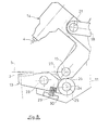
- the pliers shown in FIG. 7, of the C type have a structure, or frame 11 carried by a machine or a manipulator robot 12. These clamps include a jaw 13 equipped with the matrix 3 and a jaw 14 fitted with the punch 4.
- the jaw 14 has at one of its ends, the punch 4 which is positioned perpendicular to the assembly plane 5, and it has at its other end a hinge pin 15 arranged by example in said plane 5, which axis of articulation 15 is carried by the frame 11.
- the jaw 14 is maneuvered by means of a jack 16 mounted on the frame 11, and whose axis 17 is parallel to the assembly plane 5.
- a link 18 provides the link between the axis 19 disposed at the end of the rod 20 of the jack 16 and a pin 21 arranged on the back of the jaw 14.
- the jaw 13 is in the form of a rocker; she is articulated and oscillates on an axis 23 which is integral with the frame 11. This axis 23 is parallel to axis 15 and is located between punch 4 and said axis 15.
- This jaw 13 has at one of its ends the matrix 3 and at its other end, under the axis 15, for example, a roller 24 which is mounted on an axis 25 integral with said jaw.
- This roller 24 is in external contact with the outline of the jaw 14, which outline, which envelopes the pivot axis 15, is arranged in the form of a cam with a profile which makes it possible to separate the matrix 3 from the plane 5 or to maintain it in said plan.
- the movement of the jaw 13 is combined or synchronized with the movement of the jaw 14. In fact, it is the movement of the jaw 14 which controls the movement and position of the jaw 13.
- the cam fitted on the jaw 14, around the axis 15, is shown 8, comprises a sector 26 which for example consists of a surface flat or hollow.
- This sector forms a sort of slope which allows movement of the roller 24 and by means of consequence of the jaw 13 and its matrix 3 relative to the plane assembly 5, when the jaw 14 and its punch 4 are brought back in the inactive position as shown in thin dashed lines in FIG. 7.
- the shape of this sector 26 can be concave or other; this sector allows actually trigger rapid movement of the rocker jaw 13 at the end of the return stroke of the movable jaw 14, by tilting it around its axis 23.
- This cam arranged directly on the movable jaw 14, comprises a second portion 27 in the form of a cylindrical arc, centered on axis 15, which keeps the jaw 13 and its matrix 3 in a stationary fixed position, during the travel of the jaw 14 and the punch 4 and in particular, during the actual operation of compression and deformation of metals.
- the jaw 13 is kept in contact with the cam of the jaw 14 and rocking by means of an elastic member consisting of a helical spring 29 which is supported on a cross member 30 secured to the frame, disposed under said jaw, between the axis 23 and the roller 24.
- This spring 29 also makes it possible to separate the jaw 13 and its matrix 3 of the assembly plane 5 in order to strip the protuberance shaped by the punch 4 in the matrix 3. Its stiffness is chosen by depending on the effort required for stripping.
- the system of jaws 13, 14 is similar to a system of trigger for jaw 14 and trigger for jaw 13.
- the jaw 13 abruptly deviates from the assembly plane 5 at the end of back stroke of jaw 14 and it resumes just as quickly stationary position in the assembly plane 5 from the start of the forward movement of the jaw 14.
- the jaw 13 is held stationary by the profile 27 of the cam fitted on the jaw 14, for practically the entire back and forth travel of the jaw 14.
- the assembly plane 5 is parallel to the axis 17 of displacement of the jack 16, in the case of FIG. 9, said assembly plane is perpendicular to this axis 17.
- This plane assembly passes for example through the axis 15 of the jaw 14, FIG. 7, while it passes through the axis 23 of the jaw 33, FIG. 9.
- clamps are type said in J.
- the jaw 33 comprises the matrix 3, which matrix is positioned and centered on the axis 17 of the jack 16.
- the jaw 34 which carries the punch 4 is disposed in the extension of the rod 20 of the jack 16.
- the jaw 34 is guided longitudinally in a sheath 35 which is part of the structure or frame 11 of the clamps.
- the piston-shaped jaw 34 is also arranged in the form of a cam or trigger to control the movement jaw 33 which behaves like a trigger.
- the jaw 33 is also in the form of a rocker articulated on the axis 23 which is carried by the frame 11.
- a spring 29 ensures as before, the recall of the rocker jaw 33 and allows the stripping of the protuberance according to the type of assembly.
- the jaw 34 has a recess 36, in hollow for example, in which is housed the roller 24 of the jaw 33 when said jaw 34 is in the retracted position, inactive.
- She also includes a rectilinear portion 37 which makes it possible to maintain the jaw 33 in fixed position, stationary, with die 3 positioned in the assembly plane 5, when the punch 4 is pushed towards said assembly plane 5, against said matrix 3.
- the recess 36 and the straight portion 37 are in fact arranged on the body 38 of the jaw 34, which body is guided in the sheath 35 of the frame 11, by means of guide sleeves 39.
- Figure 10 shows the jaws in the inactive position after the recoil of the rod 20 of the jack 16.
- the body 38 of the jaw is associated with the end of the rod of the jack by an assembly 40 of the Tee type by example.
- This body 38 is of square or cylindrical section with a flat to form the rectilinear portion 37, and a concave recess 36 for allow tilting of the jaw 33.
- roller 24 of the rocker jaw 33 is located in the recess 36, pressed in this recess thanks to the spring 29 which is interposed between the cross member 30 of the frame 11 and the branch of the jaw 33 which carries said roller 24.
- This spring 29 also provides the clearance of the matrix 3 with respect to the protuberance, and its spacing of the assembly plane 5.
- Figure 11 shows another alternative embodiment for a model of pliers in C.
- This embodiment is similar to that of FIG. 7.
- the variant relates essentially to the fact that the jaw 43 is fixed, forming part of the structure or frame 11 of the clamps. It is support 42 of the matrix 3 which is mobile, guided in the jaw 43 along an axis 44 perpendicular to the assembly plane 5.
- the matrix 3 is mobile via its support 42 under the effect of a cam 45 of the rectilinear displacement type, perpendicular to axis 44.
- This cam is guided in the jaw 43, under the matrix 3 and it has a first surface 46 which allows to the support 42 of said matrix 3 to move away from the assembly plane 5 and a surface 47 which makes it possible to position this same support 42 in the assembly plan 5.
- the two surfaces or flats 46, 47 are separated by a ramp 48 whose slope is of the order of 30 °.
- the cam 45 actually corresponds to the rod of a jack 50 arranged by example directly in the jaw 43.
- the piston 51 of the jack 50 is integral with cam 45.
- This piston 51 is on one side subjected to the action of actuator fluid and, on the other hand, subjected to the action of an organ elastic like helical spring 52 which tends to bring it back into position inactive, which inactive position corresponds to the withdrawal position of the matrix 3 that is to say at a position where this matrix 3 is removed from the plane assembly 5.
- the spring 52 is interposed between the piston 51 and a fitted support in the jaw 43.
- the matrix 3 automatically deviates from the assembly plane under the effect of elastic bodies in the form of Belleville washers 53 which are interposed between a support arranged in the jaw 43 and a head fitted at the end of the support 42 of said matrix 3. These members elastic 53 also allow to undress the protrusion 2.
- the movable jaw 14 is actuated by means of the jack 16.
- the control device for this jack 16 comprises means which allow actuation at first, the cylinder 50 and its rod under cam shape 45, to place the die 3 in a stationary position at the less during the time of shaping and completion of the assembly.
- Assembly tools can also be replaced according to the necessities by jaws which make it possible to carry out operations of workpiece clamping.
Landscapes
- Engineering & Computer Science (AREA)
- Mechanical Engineering (AREA)
- Mounting, Exchange, And Manufacturing Of Dies (AREA)
Applications Claiming Priority (2)
| Application Number | Priority Date | Filing Date | Title |
|---|---|---|---|
| FR9608041A FR2750063B1 (fr) | 1996-06-25 | 1996-06-25 | Pinces pour l'assemblage de produits metallurgiques plats |
| FR9608041 | 1996-06-25 |
Publications (1)
| Publication Number | Publication Date |
|---|---|
| EP0815980A1 true EP0815980A1 (de) | 1998-01-07 |
Family
ID=9493500
Family Applications (1)
| Application Number | Title | Priority Date | Filing Date |
|---|---|---|---|
| EP97401463A Withdrawn EP0815980A1 (de) | 1996-06-25 | 1997-06-23 | Zangen zum Verbinden dünner metallischer Platten |
Country Status (2)
| Country | Link |
|---|---|
| EP (1) | EP0815980A1 (de) |
| FR (1) | FR2750063B1 (de) |
Cited By (16)
| Publication number | Priority date | Publication date | Assignee | Title |
|---|---|---|---|---|
| EP1010838A1 (de) * | 1998-12-19 | 2000-06-21 | Wilhelm Layher Vermögensverwaltungs-GmbH | Laufplanke aus Metall |
| EP1010837A1 (de) * | 1998-12-19 | 2000-06-21 | Wilhelm Layher Vermögensverwaltungs-GmbH | Metall-Laufplanke |
| EP1132158A1 (de) * | 2000-03-06 | 2001-09-12 | Hahn, Ortwin, Prof. Dr.-Ing. | Verfahren und Vorrichtung zum mechanischen Fügen von metallischen Bauteilen |
| EP1163963A1 (de) * | 2000-06-14 | 2001-12-19 | Emhart Inc. | Nietvorrichtung |
| EP1484124A1 (de) * | 2003-06-05 | 2004-12-08 | Newfrey LLC | Vorrichtung zur Korrektur des Setzens von Stanznieten, zur Entfernung von Stanznieten und zur Setzung von Nieten |
| DE102004003909A1 (de) * | 2004-01-27 | 2005-08-18 | Adam Opel Ag | Verfahren zum Verbinden zweier oder mehrerer Bleche oder Profilteile, insbesondere eines Karosseriesegments, sowie Karosseriesegment |
| FR2884851A1 (fr) * | 2005-04-25 | 2006-10-27 | Massimo Valente | Porte de securite a blindage metallique |
| WO2007112720A1 (de) * | 2006-03-31 | 2007-10-11 | Eckold Gmbh & Co. Kg | Verfahren und werkzeugeinrichtung zum umformen |
| US20120260491A1 (en) * | 2009-10-16 | 2012-10-18 | Bollhoff Verbindungstechnik Gmbh | Setting device, supply module for the setting device, and a joining method for connecting at least two components |
| CN104439766A (zh) * | 2014-09-17 | 2015-03-25 | 安徽巨一自动化装备有限公司 | 一种用于预搭扣自动折弯的机构 |
| WO2016002882A1 (ja) * | 2014-07-03 | 2016-01-07 | 日新製鋼株式会社 | かしめ装置 |
| US9339899B2 (en) | 2010-11-10 | 2016-05-17 | Henrob Limited | Fastening method and apparatus |
| DE102015007295B3 (de) * | 2015-06-10 | 2016-09-08 | Audi Ag | Setzvorrichtung |
| CN108160858A (zh) * | 2017-12-26 | 2018-06-15 | 安徽瑞祥工业有限公司 | 一种包边压紧机构 |
| US20200230751A1 (en) * | 2018-09-11 | 2020-07-23 | Jr Automation Technologies, Llc | Fastener Welding Apparatus |
| CN119216956A (zh) * | 2024-11-29 | 2024-12-31 | 长沙红运环保科技有限公司 | 一种用于金属门板加工的半自动焊接设备 |
Families Citing this family (1)
| Publication number | Priority date | Publication date | Assignee | Title |
|---|---|---|---|---|
| CN103920821B (zh) * | 2013-12-19 | 2015-10-21 | 宁波天龙电子股份有限公司 | 一种多工位组合工装 |
Citations (4)
| Publication number | Priority date | Publication date | Assignee | Title |
|---|---|---|---|---|
| FR2056005A5 (en) * | 1969-08-18 | 1971-05-14 | Molino Angelo | Punch press for connecting sheets of metal |
| EP0215449A1 (de) * | 1985-09-14 | 1987-03-25 | RAPP, Eugen | Verfahren und Vorrichtung zum Verbinden dünner Platten |
| DE3726392A1 (de) * | 1987-08-07 | 1989-02-16 | Kuka Schweissanlagen & Roboter | Verfahren zum verbinden aufeinanderliegender duenner platten oder plattenabschnitte |
| US5315743A (en) * | 1990-05-18 | 1994-05-31 | Tech-Line Engineering Co. | Apparatus for forming a clinch joint |
-
1996
- 1996-06-25 FR FR9608041A patent/FR2750063B1/fr not_active Expired - Fee Related
-
1997
- 1997-06-23 EP EP97401463A patent/EP0815980A1/de not_active Withdrawn
Patent Citations (4)
| Publication number | Priority date | Publication date | Assignee | Title |
|---|---|---|---|---|
| FR2056005A5 (en) * | 1969-08-18 | 1971-05-14 | Molino Angelo | Punch press for connecting sheets of metal |
| EP0215449A1 (de) * | 1985-09-14 | 1987-03-25 | RAPP, Eugen | Verfahren und Vorrichtung zum Verbinden dünner Platten |
| DE3726392A1 (de) * | 1987-08-07 | 1989-02-16 | Kuka Schweissanlagen & Roboter | Verfahren zum verbinden aufeinanderliegender duenner platten oder plattenabschnitte |
| US5315743A (en) * | 1990-05-18 | 1994-05-31 | Tech-Line Engineering Co. | Apparatus for forming a clinch joint |
Cited By (24)
| Publication number | Priority date | Publication date | Assignee | Title |
|---|---|---|---|---|
| EP1010837A1 (de) * | 1998-12-19 | 2000-06-21 | Wilhelm Layher Vermögensverwaltungs-GmbH | Metall-Laufplanke |
| EP1010838A1 (de) * | 1998-12-19 | 2000-06-21 | Wilhelm Layher Vermögensverwaltungs-GmbH | Laufplanke aus Metall |
| EP1132158A1 (de) * | 2000-03-06 | 2001-09-12 | Hahn, Ortwin, Prof. Dr.-Ing. | Verfahren und Vorrichtung zum mechanischen Fügen von metallischen Bauteilen |
| EP1163963A1 (de) * | 2000-06-14 | 2001-12-19 | Emhart Inc. | Nietvorrichtung |
| EP1484124A1 (de) * | 2003-06-05 | 2004-12-08 | Newfrey LLC | Vorrichtung zur Korrektur des Setzens von Stanznieten, zur Entfernung von Stanznieten und zur Setzung von Nieten |
| DE102004003909B4 (de) * | 2004-01-27 | 2010-09-09 | GM Global Technology Operations, Inc., Detroit | Pressschweißverfahren zum Verbinden zweier oder mehrerer Bleche oder Profilteile, insbesondere eines Karosseriesegments, dessen Verwendung sowie Karosseriesegment |
| DE102004003909A1 (de) * | 2004-01-27 | 2005-08-18 | Adam Opel Ag | Verfahren zum Verbinden zweier oder mehrerer Bleche oder Profilteile, insbesondere eines Karosseriesegments, sowie Karosseriesegment |
| FR2884851A1 (fr) * | 2005-04-25 | 2006-10-27 | Massimo Valente | Porte de securite a blindage metallique |
| WO2007112720A1 (de) * | 2006-03-31 | 2007-10-11 | Eckold Gmbh & Co. Kg | Verfahren und werkzeugeinrichtung zum umformen |
| DE102006015458B4 (de) | 2006-03-31 | 2019-02-28 | Eckold Gmbh & Co. Kg | Verfahren und Werkzeugeinrichtung zum Umformen |
| US20120260491A1 (en) * | 2009-10-16 | 2012-10-18 | Bollhoff Verbindungstechnik Gmbh | Setting device, supply module for the setting device, and a joining method for connecting at least two components |
| US9149863B2 (en) * | 2009-10-16 | 2015-10-06 | Bollhoff Verbindungstechnik Gmbh | Setting device, supply module for the setting device, and a joining method for connecting at least two components |
| US9339899B2 (en) | 2010-11-10 | 2016-05-17 | Henrob Limited | Fastening method and apparatus |
| US10005119B2 (en) | 2010-11-10 | 2018-06-26 | Henrob Limited | Fastening method and apparatus |
| US9387557B2 (en) | 2010-11-10 | 2016-07-12 | Henrob Limited | Riveting method and apparatus |
| WO2016002882A1 (ja) * | 2014-07-03 | 2016-01-07 | 日新製鋼株式会社 | かしめ装置 |
| JP2016013569A (ja) * | 2014-07-03 | 2016-01-28 | パナホーム株式会社 | かしめ装置 |
| CN104439766B (zh) * | 2014-09-17 | 2016-01-20 | 安徽巨一自动化装备有限公司 | 一种用于预搭扣自动折弯的机构 |
| CN104439766A (zh) * | 2014-09-17 | 2015-03-25 | 安徽巨一自动化装备有限公司 | 一种用于预搭扣自动折弯的机构 |
| DE102015007295B3 (de) * | 2015-06-10 | 2016-09-08 | Audi Ag | Setzvorrichtung |
| CN108160858A (zh) * | 2017-12-26 | 2018-06-15 | 安徽瑞祥工业有限公司 | 一种包边压紧机构 |
| US20200230751A1 (en) * | 2018-09-11 | 2020-07-23 | Jr Automation Technologies, Llc | Fastener Welding Apparatus |
| US11654517B2 (en) * | 2018-09-11 | 2023-05-23 | Jr Automation Technologies, Llc | Fastener welding apparatus |
| CN119216956A (zh) * | 2024-11-29 | 2024-12-31 | 长沙红运环保科技有限公司 | 一种用于金属门板加工的半自动焊接设备 |
Also Published As
| Publication number | Publication date |
|---|---|
| FR2750063B1 (fr) | 1998-09-18 |
| FR2750063A1 (fr) | 1997-12-26 |
Similar Documents
| Publication | Publication Date | Title |
|---|---|---|
| EP0815980A1 (de) | Zangen zum Verbinden dünner metallischer Platten | |
| EP0622152B1 (de) | Bearbeitungsstation mit Stümpfpositionierung und Laserstrahlschweissen von zwei Blechkanten | |
| FR2677285A1 (fr) | Tete de soudage a laser. | |
| EP0089904B1 (de) | Flachbiegeeinrichtung | |
| EP0383704A1 (de) | Antriebsvorrichtung für Bahn-, Blatt- oder Drahtmaterial | |
| EP0301964B1 (de) | Vorrichtung zum Bohren und Nieten | |
| FR2647696A1 (fr) | Ensemble d'outillage pour rivetage de pieces | |
| EP0242309B1 (de) | Biegepresse mit Schwenkbalken | |
| WO1998028110A1 (fr) | Outil pilote de centrage et serrage | |
| FR2640904A1 (de) | ||
| FR2640532A1 (fr) | Appareils de positionnement de pieces sous forme de feuilles et dispositifs de serrage | |
| FR2660219A1 (fr) | Machine a bouteroller. | |
| EP0018868B1 (de) | Vorrichtung zum in der Längsrichtung Schneiden von Brammen mittels Sauerstoffbrennschneiden | |
| EP0407565B1 (de) | Vorrichtung zum herausheben eines auf länge geschnittenen werkstücks aus einer motorangetriebenen säge | |
| EP0307293B1 (de) | Zusammenkuppelsystem für zwei Körper, z.B. einen Transportwagen und eine Bearbeitungsstation | |
| FR3045425A1 (fr) | Module de poinconnage et de soudage | |
| FR2564023A1 (fr) | Pince porte-outil | |
| EP0370914A1 (de) | Spannkopf mit Spielausgleich | |
| EP0900603A1 (de) | Presse zum Formen eines Blechzuschnittes | |
| FR2945760A1 (fr) | Dispositif de fixation rapide par serrage d'un organe | |
| FR2807685A1 (fr) | Outil de centrage et de serrage | |
| FR2459105A1 (fr) | Pince pour le soudage par points de deux elements | |
| FR2672831A1 (fr) | Machine de soudage par friction a haute cadence. | |
| EP1690619B1 (de) | Schneidtisch für Metallbleche | |
| FR2642691A1 (fr) | Appareil destine a etre fixe sur un poignet de robot pour assurer la pose d'un joint de porte |
Legal Events
| Date | Code | Title | Description |
|---|---|---|---|
| PUAI | Public reference made under article 153(3) epc to a published international application that has entered the european phase |
Free format text: ORIGINAL CODE: 0009012 |
|
| AK | Designated contracting states |
Kind code of ref document: A1 Designated state(s): DE ES GB IT SE |
|
| RBV | Designated contracting states (corrected) |
Designated state(s): DE ES GB IT SE |
|
| 17P | Request for examination filed |
Effective date: 19980707 |
|
| AKX | Designation fees paid |
Free format text: DE ES GB IT SE |
|
| RBV | Designated contracting states (corrected) |
Designated state(s): DE ES GB IT SE |
|
| 17Q | First examination report despatched |
Effective date: 20000904 |
|
| STAA | Information on the status of an ep patent application or granted ep patent |
Free format text: STATUS: THE APPLICATION IS DEEMED TO BE WITHDRAWN |
|
| 18D | Application deemed to be withdrawn |
Effective date: 20010103 |